
Working in an engineering firm generally means working on a team. This team can be as simple as a technician and an engineer, or it can include dozens of people spread across several disciplines such as architecture, civil engineering, landscape architecture, irrigation, and project management. No matter the team size or makeup, it's important that team members communicate so that they're always working with the latest information.
To solve the communication problem, and to make it more efficient for multiple team members to work on the same project together, Civil 3D contains the Data Shortcuts (DS) feature. This feature lets you share data between drawings quickly and easily. Although the types of objects are somewhat limited, most users find they suffice, and that their ease of use makes DS a great tool.
This chapter covers the following topics:
The difference between data shortcuts and Xrefs
Creating new project template folders
Creating new projects in Civil 3D
Creating new data shortcuts and references
Updating references
Repairing broken or lost references
Data shortcuts allow the cross-referencing of design data between drawings. To this end, the data is what is made available, and it's important to note that the appearance can be entirely different between the host and any number of data shortcuts. We'll use the term data shortcut or, more simply, shortcut when we discuss selecting, modifying, or updating these links between files.
There are two primary situations in which you need data or information across drawings, and they are addressed with external references (Xrefs) or shortcuts. These two options are similar but not the same. Let's compare:
Xref functionality: Used when the goal is to get a picture of the information in question. Xrefs can be changed by using the layer control, Xref clips, and other drawing-element controls. Although they can be used for labeling across files in Civil 3D 2010, the fact that you have to bring over the entire file to label one component is a disadvantage.
Shortcut functionality: Brings over the design information, but generally ignores the display. Shortcuts work only with Civil 3D objects, so they will have their own styles applied. This may seem like duplicitous work because you have already assigned styles and labels in one drawing and have to do it again, but it offers the advantage that you can have completely different views of the same data in different drawings.
Only Civil 3D objects can be used with shortcuts, and even then some objects are not available through shortcuts. The following objects are available for use through data shortcuts:
Alignments
Surfaces
Profile data
Pipe networks
View frame groups
You might expect that corridor, parcel, assembly, point, or point group information would be available through the shortcut mechanism, but they are not. Parcels and corridors can be accessed only via Xref, but once they've been Xreferenced, you can use the normal labeling techniques and styles. Now that you've looked at what objects you can tackle with shortcuts, you'll learn how to create them in the next section.
Shortcut files are simply XML files that have pointers back to the drawing containing the object in question. These shortcuts are managed through Prospector and are stored in a working folder. Creating shortcuts is a matter of setting a working folder, creating a shortcut folder within that, and then creating the shortcut files. You'll look at all three steps in this section.
As a precursor to making your first project, you should establish what a typical folder structure looks like. Civil 3D includes a mechanism for copying a typical project folder structure into each new project. By creating a blank copy of the folder structure you'd like to have in place for your projects, you can use that as the starting point when a new project is created in Civil 3D. In this exercise, you'll set up a prototype folder structure for use later in creating new projects.
Open Windows Explorer and navigate to
C:Civil 3D Project Templates.Create a new folder titled
Introducing.Inside
Introducing, create folders calledSurvey, Engineering, Architecture, Word, andCon Docs, as shown in Figure 14.1
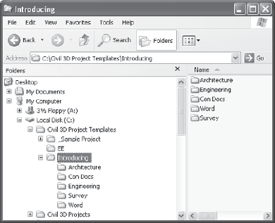
This structure will be displayed inside Civil 3D and in the working folder when a project is created. We've included a Word folder as an example of other, non-Civil 3D-related folders you might have in your project setup for users outside the CAD team, such as accountants or the project manager. These files and folders would be added to each new project created via Civil 3D. This is a great way to include project checklists, standard details sheets, or a template cover sheet that contains your logo and company information. You can set up template folders to handle a variety of situations and make life easier on other users. You may close the Civil 3D Project Templates folder.
For the most part, you can mentally substitute "project folder" for "working folder" when you are working with DS. Then you can substitute "project folder" for "data shortcuts folder," and the whole thing will make a lot more sense. The working folder will contain a number of projects, each in turn having a shortcuts folder where the shortcut files actually reside. Each time you create a new shortcut folder within the Prospector framework, you'll have the opportunity to create a full project structure. In the following exercise, you'll set the working folder and create a new project:
Create a new blank drawing using any template.
Within Prospector, make sure the View drop-down list is set to Master View.
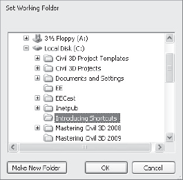
Right-click the Data Shortcuts branch and select Set Working Folder to display the Browse for Folder dialog shown in Figure 14.2
Click Local Disk (C:) to highlight it, and then click the Make New Folder button.
Type Introducing Shortcuts as the folder name and click OK to dismiss the dialog.
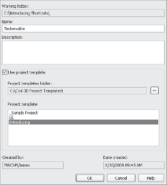
Right-click the Data Shortcuts branch in Prospector, and select New Data Shortcuts Folder to display the New Data Shortcut Folder dialog shown in Figure 14.3
Type Timberwilde for the folder name, and toggle on the Select option to use the project template as shown in Figure 14.3.
Select the Introducing folder from the list as shown, and click OK to dismiss the dialog. Congratulations! You've made a new Civil 3D project. Notice that the Data Shortcuts branch in Prospector now reflects the path of the Timberwilde project.
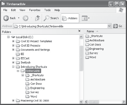
If you open Windows Explorer and navigate to C:Introducing ShortcutsTimberwilde, you'll see the folder from the Mastering project template plus a special folder named _Shortcuts, as shown in Figure 14.4. One common issue that arises is that you already have a project folder inside the working folder. This is typically done during some bidding or marketing work, or during contract preparation. If you already have a project folder established, it will not show up in Civil 3D unless there is a _Shortcuts folder inside it. To this end, you can manually make this folder. There's nothing special about it, except that it has to exist.
Remember, the working folder and data shortcuts folder are simply Civil 3D terms for a projects folder and individual projects. If you're familiar with Land Desktop, the working folder is similar to the project path, with various projects. Finally, don't forget that drawing files and working folders aren't tied together. When you change drawings, the data shortcuts folder will not change automatically. You must right-click the Data Shortcuts branch and select a different data shortcuts folder.
You've created a data shortcuts folder, so it's time to put it to use. One caution when working with data shortcuts: a drawing creating a shortcut for a given project can actually be stored anywhere. This could lead to confusion for users trying to determine what file is tied to what Civil 3D object, so it is really best practice to keep the drawing files in the same rough location as your shortcut files. For the purposes of these exercises though, you'll just leave the data in the default location instead of moving it first. In the following exercise, you'll start working with shortcuts by publishing data shortcuts for the alignments, profiles, and surfaces in your project:
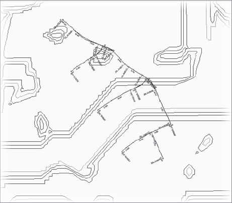
Open the
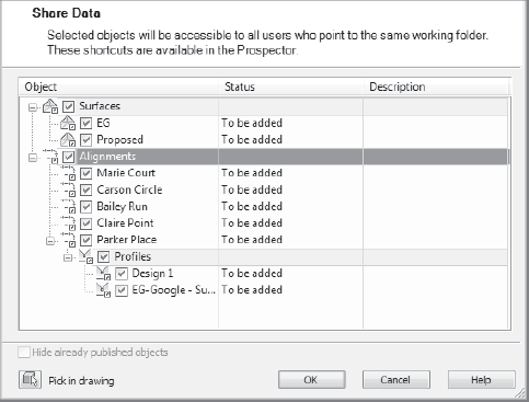
Creating Shortcuts.dwgfile. (Remember, all data files can be downloaded fromwww.sybex.com/go/introducingcivil3d2010.) This drawing contains surface, alignment, and profile data, ready to be shared with the rest of the team. (See Figure 14.5In Prospector, right-click the Data Shortcuts branch, and select Create Data Shortcuts to display the Create Data Shortcuts dialog shown in Figure 14.6
Check the Surfaces and Alignments options, and the subitems will all be selected. Note that the Profiles associated with the Parker Place alignment are also being selected for publishing.
Click OK to dismiss the dialog and create the data shortcuts.
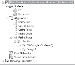
In Prospector, expand the branches under the Data Shortcuts heading as shown in Figure 14.7, and you should see all of the relevant data listed. The listing here indicates that the object is ready to be referenced in another drawing file.

Civil 3D manages the XML data reference files for you. They are stored in the magic _Shortcuts folder as individual XML files. You can review these XML files using XML Notepad. You can still open and view these files, but notice that the first comment in the XML file is PLEASE DO NOT EDIT THIS FILE! In the past, some users found they needed to edit XML files to fix broken or lost references. This is no longer necessary with the addition of the Data Shortcuts Editor, which you look at later in this chapter.
Now that you've created the shortcut XML files to act as pointers back to the original drawing, you'll use them in other ways and locations. Once a reference is in place, it's a simple matter to update the reference and see any changes in the original file reflected in the reference object. In this section, you'll look at creating and exploring these references, and then learn about updating or editing them.
Shortcut references are made using the Data Shortcuts branch within Prospector. In the following exercise, you'll create references to the objects you previously published to the Timberwilde project:
Open the
Creating References.dwgfile. This is an empty file built on the Extended template.In Prospector, expand Data Shortcuts → Alignments.
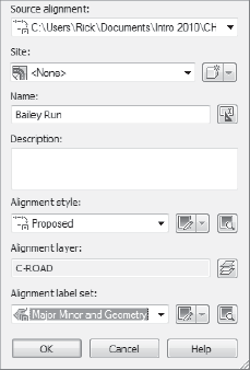
Right-click the Bailey Run alignment and select Create Reference to display the Create Alignment Reference dialog shown in Figure 14.8
Set the Alignment Style to Proposed and the Alignment Label Set to Major Minor and Geometry Points as shown in Figure 14.8.
Click OK to close the dialog.
Perform a zoom extents to find this new alignment.
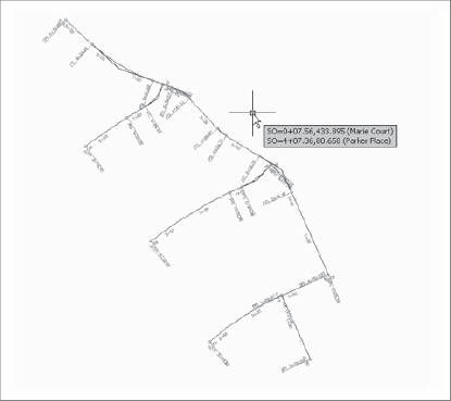
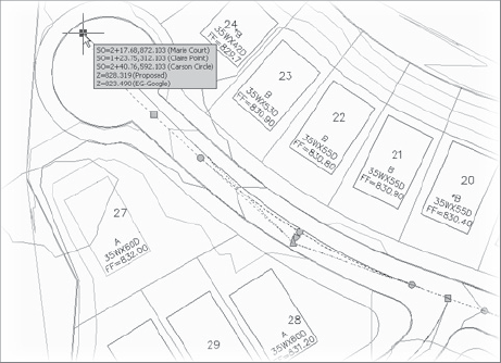
Repeat steps 3 through 5 for the Carson Circle, Claire Point, Marie Court, and Parker Place alignments in the shortcuts list. When complete, your screen should look similar to Figure 14.9
Note the tooltip in Figure 14.9 indicates station and offset data, reflecting the fact that data references bring data, not just pictures of data. Each of these alignments is simply a pointer back to the original file. They can be stylized, stationed, or labeled, but the definition of the alignment cannot be changed. This is more clearly illustrated in a surface, so you'll add a surface reference in the following exercise:
Expand Data Shortcuts → Surfaces.
Right-click the EG surface and select Create Reference to display the Create Surface Reference dialog.
Change the Surface Style to Contours 1′ & 5′ (Background), and then click OK. Your screen should look like Figure 14.10
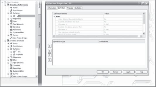
Expand the Surfaces branch of Prospector and the EG surface as shown in Figure 14.11
Right-click the EG surface and select Surface Properties.
Here are a couple of important things to note:
The small arrow next to the EG surface name indicates that the surface is a shortcut.
There's no Definition branch under the EG surface. Additionally, in the Surface Properties dialog, the entire Definition tab is grayed out, making it impossible to change by using a shortcut.
Click OK to close the dialog.
To reference a live object in the current drawing, simply right-click its name and select Promote. This breaks the link to the source information and creates an editable object in the current drawing. This technique can be very handy for playing with alternative designs, copying profile or alignment data into a temporary drawing, and editing without concern that you are destroying the currently valid design data.
Now that you've created a file with a group of references, you'll look at how changes in the source drawing are reflected in this file.
As it is, if the reference were just a copy of the original data, you'd have done nothing more than cut and paste the object from one drawing to another. The benefit of using shortcuts is just like Xrefs: when a change is made in the source, it's reflected in the reference drawing. In this section, you'll make a few changes and look at the updating process, and then you'll see how to add to the data shortcut listings in Prospector.
When it's necessary to make a change, it can sometimes be confusing to remember which file you were in when you originally created a now-referenced object. Thankfully, you can use the tools in the Data Shortcut palette to very simply jump back to that file, make the changes, and refresh the reference, which is what you'll be doing in the following exercise:
In Prospector, expand Data Shortcuts → Alignments.
Right-click Bailey Run, and select Open Source Drawing. You can also do this by selecting the object in the drawing window and right-clicking to access the shortcut menu. The Open Source Drawing command is on the shortcut menu when a reference object is selected.
Select the Parker Place alignment and make a grip-edit to Parker Place's northern end, dragging it up and further north, as shown in Figure 14.2
Save the drawing.
Once a change is made in the source drawing, Civil 3D will synchronize references the next time they are opened. In the current exercise, the reference drawing is already open. The following steps show you how the alert mechanism works in this situation.
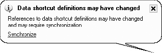
Use Control-tab to switch to make the
Creating References.dwgfile active. (Alternately, you can use the QuickView Drawings button at the bottom of your civil 3D window to change drawings.) An alert bubble like the one shown in Figure 14.13 should appear. This may take a few minutes, but if you expand Creating References → Alignments in Prospector, you will also see a series of warning chevrons. You might look for this change manually if one of your team members e-mails or calls to tell you they've made a design change and you don't want to wait for the alert bubble.Click Synchronize in the alert bubble to bring your drawing current with the design file and dismiss the Panorama window if you'd like. If you don't see the alert bubble, right-click each alignment branch in Prospector and select Synchronize. Your drawing will update, and the Parker Place alignment will reflect the change in the source. If you do not get the bubble, you can select individual references within Prospector and right-click them to access the Synchronize command.
Shockingly enough, the Open Source Drawing command is the only way to track down the source of a shortcut. There is no way to simply list the object and recognize the filename, or see the filename in a table.
Updating references as in the preceding exercise is simple enough and works well once file relationships are established. But suppose there is a change in the file structure of the source information and you need to make a change? You'll look at that in the next section.
Designs change often—there's no question about that. And using shortcuts to keep all the members of the design team on the same page is a great idea. But in the scenario you're working with in this chapter, what happens if new, additional alignment data is added to the source file? You'll explore that in this exercise:
Return to the
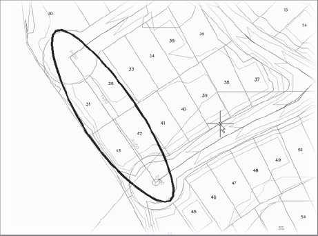
Creating Shortcuts.dwgfile.Create a new alignment, named Loop Road, extending from the Claire Point cul-de-sac to the Carson Circle cul-de-sac, ignoring the fact that it crosses a number of parcels. (Part of the fun with Civil 3D is the ability to quickly experiment!) Your screen should look like Figure 14.14, with the new alignment circled.
Save the file.
In Prospector, right-click Data Shortcuts and select Create Data Shortcuts to display the Create Data Shortcuts dialog.
Check the Hide Already Published Objects option in the lower-left corner of the dialog to make finding the new object easier.
Check the Loop Road alignment, and then click OK to dismiss the dialog. Save the Creating Shortcuts drawing!
Switch back to Creating References file, and add the Loop Road alignment to your data shortcuts as in earlier examples.
By using shortcuts to handle and distribute design information, it's quite simple to keep adding information to the design as it progresses. This means that designs really don't have to be complete before other team members can begin working with the data. It's important to remember that simply saving a file does not create new shortcut files for all of the Civil 3D objects contained in that file—they have to be created from the Data Shortcuts branch.
One of the dangers of linking things together is that eventually you'll have to deal with broken links. As files are renamed, or moved from the Preliminary folder to the Production folder, the data shortcut files that point back simply get lost. Thankfully, Civil 3D includes a tool for handling broken or edited links: the Data Shortcuts Editor. You explore that tool in the following exercise:
Open the file
Repairing References.dwg. This file contains a number of references pointing to a file that no longer exists, and Panorama should appear to tell you that four problems were found. Close the Panorama window.In Prospector, expand Repairing References → Surfaces and you will see that Proposed has a warning chevron next to it.
Right-click Proposed and select Repair Broken References from the shortcut menu to display the Choose the File Containing the Referenced Object dialog.
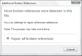
Navigate to the
Creating Shortcuts.dwgfile in the data set. Click OK to dismiss the Choose the File Containing the Referenced Object dialog. An Additional Broken References dialog will appear as shown in Figure 14.15, offering you the option to repair all the references or cancel.Click the Repair All Broken References button to close the Additional Broken References dialog. Civil 3D will crawl through the file linked in step 4, and attempt to match the Civil 3D objects with broken references to objects in the selected drawing.
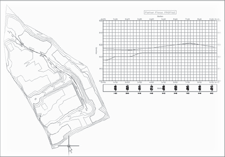
Perform a zoom extents, and your drawing should look like Figure 14.16, with a surface, alignment, and profile view.
The ability to repair broken links helps make file management a bit easier, but there will be times when you need to completely change the path of a shortcut to point to a new file. To do this, you'll need to use the Data Shortcuts Editor.
The Data Shortcuts Editor (DSE) is used to update or change the file to which a shortcut points. This can happen when an alternative design file is approved, or when you move from preliminary to final design. In the following exercise, you'll change the EG surface shortcut to point at a surveyed site surface instead of the Google Earth surface the shortcut file was previously using:
Make sure
Creating References.dwgis still open.In Windows, go to Start → All Programs → Autodesk → Autodesk Civil 3D 2010 → Data Shortcuts Editor to load DSE.
Select File → Open Data Shortcuts Folder to display the Browse for Folder dialog.
Navigate to
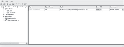
C:Introducing ShortcutsTimberwilde, and then click OK to dismiss the Browse for Folder dialog.On the left, select the Surfaces branch to isolate the surfaces. Your DSE should look similar to Figure 14.17. (Your paths will be different from ours.)
Click the Source File column on the EG row, and type XTO.dwg as the Source File Name.
Click the Handle Only drop-down menu and change it to Handle or Name.
Click the Save button in the DSE and switch back to Civil 3D. You should still be in the
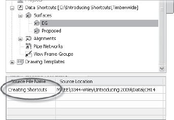
Creating Referencesdrawing file.In Prospector, select the Data Shortcuts → Surfaces → EG branch and note that the Source File Name is shown as Creating Shortcuts (see Figure 14.18).
Right-click the Data Shortcuts branch and select Validate Data Shortcuts. Prospector will alert you of a broken reference.
Expand Data Shortcuts → Surfaces. Right-click EG and select Repair Broken Shortcut.
Scroll up within Prospector, and expand the Surfaces branch.
Right-click EG and select Synchronize. Your screen should look like Figure 14.19, showing a completely different surface as the EG surface.

The ability to modify and repoint the shortcut files to new and improved information during a project without losing style or label settings is invaluable. However, when you use this function, be sure to validate and then synchronize.
Working with data across projects and data files is part of working with Civil 3D in a team environment. You should set up this process slowly: get a project template in place, add the design files, and then create references to bring your design into the construction documents. The ability to begin this third process while the design is still in flux is the real power of the application, making it possible to begin the task of documentation shortly after a conceptual design is begun. The ability to add and refine data throughout the process without having to start over on the documents process is where Civil 3D shines and lets your team work in new, more efficient ways.