
Pipe networks are fundamental parts of many civil engineering projects. New development, municipal design, and rehabilitation projects frequently include gravity systems, such as sanitary sewers and storm drainage. Civil 3D provides tools for pipe network design and editing that is dynamically tied in with labels, profile views, and tables.
This chapter includes the following topics:
Creating a sanitary sewer pipe network
Drawing a sanitary sewer network in profile view
Creating an alignment from storm drainage network parts
Labeling a pipe network in profile view
Showing pipe crossings in profile view
Creating a dynamic pipe table
Editing a pipe network
The municipality for this sample project requires that the site be serviced with a gravity sewer system. Before Civil 3D, the designer might have taken a paper copy of the plan, sketched a few different horizontal alignments with a red pen, and made estimates for rim elevations before creating a spreadsheet for iterating the vertical design. Then, once the network was almost entirely ironed out, the sketch and spreadsheet would be handed off to a technician for drafting.
With Civil 3D, that sketch can be done right in the drawing. As the model is created, the program gives instant feedback regarding rim elevation, slopes, and inverts. Pipe and structure rules can be established to assist the designer in maintaining minimum slopes and cover. Pipe and structure styles can be created to make sure the plan has the correct cosmetic appearance.
The following exercise will lead you through building a sanitary sewer pipe network, including several branches and associated labeling:
Open the drawing file
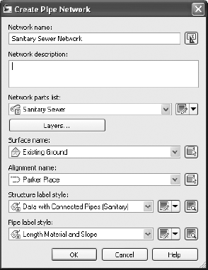
Pipes1.dwg. (All drawings can downloaded fromwww.sybex.com/go/introducingcivil3d2010.) This drawing contains a surface, alignment, storm pipe network, and profile. The surface and alignment styles are set to _No Display.From the Home tab's Create Design panel, select Pipe Network → Pipe Network Creation Tools. The Create Pipe Network dialog will appear.
In the Create Pipe Network dialog, change the Network name to Sanitary Sewer Network. Verify that the Sanitary Sewer parts list, the existing ground surface, and Parker Place for the alignment are selected. Change the Structure Label Style to Data with Connected Pipes (Sanitary), and change the Pipe Label Style to Length Material and Slope (if they are not already set). The dialog should now look like Figure 13.1.
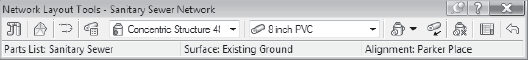
Click OK. The Network Layout Tools toolbar will appear. Verify that the Network Layout Tools toolbar is set so that the Concentric Structure 48 Dia 18 Frame 24 cone is selected and the 8 Inch PVC is selected, as shown in Figure 13.2.

The command line will now read
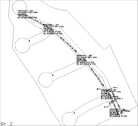
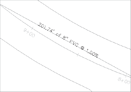
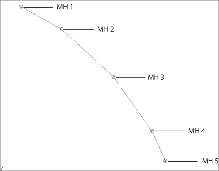
Specify next structure insertion point or [Curve]:. Use your center osnap to continue placing structures for the remaining four markers along Parker Place, as shown in Figure 13.4. (Your labels will be moved out of the way later in the exercise.)Note that labeled pipes have appeared between each structure as shown in Figure 13.5. Press Enter to exit the command. The Network Layout Tools toolbar will remain on the screen.
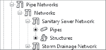
On the Prospector tab of the Toolspace, locate the Sanitary Sewer Network under the Pipe Networks tree, as shown in Figure 13.6.
Expand the Sanitary Sewer Network branch, and highlight the Structures entry. A list of structures will appear in the item view at the bottom of the Prospector.
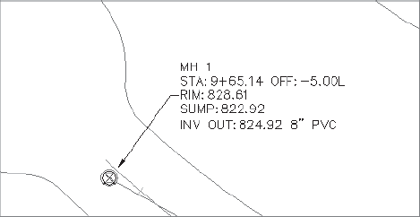
Use the Name column to rename each Manhole according to Figure 13.7. Note that once you change each name in Prospector, the plan labels immediately change to match.
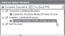
Back in the drawing, locate the Network Layout Tools toolbar. (If this toolbar has disappeared, select any pipe in the network, right-click, and choose Edit Network.) Use the structure pull-down list to switch from Concentric Structure to Eccentric Structure (Figure 13.8).
Click the Draw Pipes and Structures button. At the
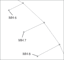
Specify the structure insertion point:prompt, place a structure at Marker A for the northeastern cul-de-sac, and then move your mouse over to MH 2 on Parker Place. A circular glyph will appear alerting you that you are about to tie into a structure. When the glyph is present, click to connect the pipe to MH 2.Use the same process from step 12 to create a pipe run from Marker B in the southeastern cul-de-sac to MH 3, and then Marker C in the southernmost cul-de-sac to MH 4.
Use Prospector to change the names of the two new manholes to the names shown in Figure 13.9.
Select the label for MH 1. A grip will appear. Grab this grip and use it to drag the label somewhere off to the side so that the plan is more readable, as in Figure 13.10. Press Esc to exit the Label Drag mode. Repeat this process for each structure label.

Once the horizontal layout has been completed for a pipe network, the engineer is usually required to produce a representation of the vertical layout in profile.
Sometimes this information is placed on a road profile, especially when the system parallels the road alignment and is contained within the right-of-way. The first leg of the sanitary sewer created in the last exercise meets this criteria—it typically holds a 5′ offset from the Parker Place centerline, and it would be appropriate to show this information on the Parker Place profile view.
The following exercise will lead you through adding the main trunk of the sanitary sewer network to the Parker Place profile view:
Open
Pipes2.dwgor continue working in the drawing from the previous exercise.From the Modify tab and Design panel on the ribbon, choose Pipe Network. The Pipe Networks contextual tab will appear. From the Network Tools panel, click Draw Parts in Profile View.
At the
Select network(s) to add to profile view or [Selected parts only]: prompt, enter S to choose selected parts only.At the
Select pipe network parts to add to profile view:prompt, select all of the pipes and structures from MH 1 through MH 5. Press Enter.At the
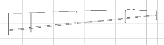
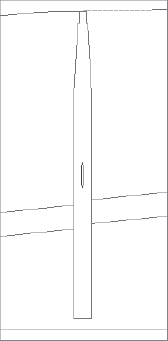
Select profile view: prompt, select the Parker Place profile view that is to the right of the site plan. The selected pipes and structures will appear in profile view, similar to what's shown in Figure 13.11 (your profile view might look slightly different).Note that the pipe runs in each cul-de-sac show as an ellipse inside the appropriate manhole where they connect to this main trunk line. See Figure 13.12.
Although the main leg of the sanitary sewer network was appropriate to show on the Parker Place profile view, the storm drainage network shown on the southern portion of the site would likely require its own profile. Because profiles are always created from an alignment, this network will require an alignment that traces key structures and pipes. Civil 3D provides a tool for creating an alignment from a pipe network.
The following exercise leads you through creating an alignment from network parts and then placing those parts on the resulting profile view:
Open
Pipes3.dwgor continue working in the drawing from the previous exercise.From the Home tab's Create Design panel, select Alignment → Create Alignment from Network Parts.
At the
Select first connected Network Part (Pipe or Structure):prompt, select CB 1.At the
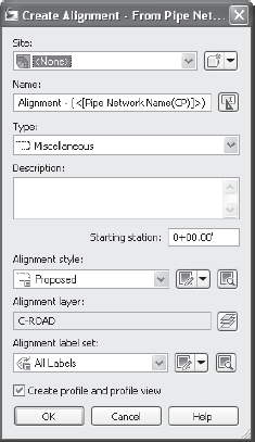
Select next Network Part or [Undo]:prompt, select Pipe A, CB 2, Pipe B, CB 4, Pipe D, and SDMH. Press Enter. The Create Alignment – From Pipe Network dialog will appear as shown in Figure 13.13.In the Create Alignment – From Pipe Network dialog, leave all of the default settings and click OK.
The Create Profile from Surface dialog will appear. Confirm that the Existing Ground surface is selected, and then click the Add button. The sampled surface entry will appear in the lower part of the dialog. Click the Draw in Profile View button. The Create Profile View dialog will appear.
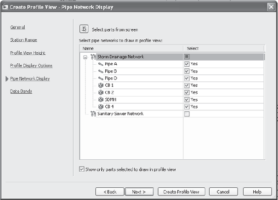
In the Create Profile View dialog, click Next four times to land on the Pipe Network Display screen (see Figure 13.14). Confirm that all of the network elements listed in step 4 are checked in this list. Click the Create Profile View button.
At the
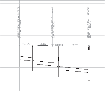
Select profile view origin: prompt, select a location in the drawing underneath the Parker Place profile view. A new profile view will appear showing the storm pipes and structures (see Figure 13.15). Some of the profile labels specify grade breaks and slopes—you can erase those if you'd like.
Once pipes and structures have been drawn on a meaningful profile view, it makes sense to add labels. These labels, like their counterparts in plan view, are dynamic to the pipe network model and will react whenever the network changes.
The following exercise shows you how to add labels to the sanitary and storm drainage networks in profile view:
Open
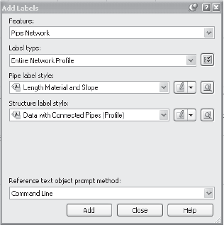
Pipes4.dwgor continue working in the drawing from the previous exercise.From the Annotate tab and Labels & Tables panel on the ribbon, choose Add Labels → Pipe Network → Add Pipe Network Labels. The Add Labels dialog will appear.
Use the Label Type pull-down list to choose Entire Network Profile.
Use the Pipe Label Style pull-down list to choose Length Material and Slope if it is not already selected.
Verify that the Structure Label Style: pull-down list is set to Data with Connected Pipes (Profile). The dialog will look like Figure 13.16. Click the Add button.
At the
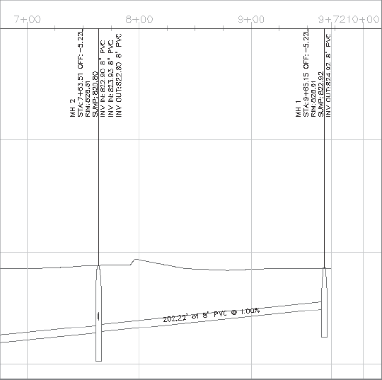
Select part (in profile view) contained in the network to be labeled: prompt, select any pipe or structure in the Parker Place profile view. Labels will appear, as shown in Figure 13.17.In the Add Labels dialog, use the Pipe Label Style: pull-down list to select Name Only. Click the Add button.
At the
Select part (in profile view) contained in the network to be labeled: prompt, select any pipe or structure in the Alignment – (Storm Drainage Network) profile view. Labels will appear.Note that the structure labels in this profile view contain question marks (???) for the station and offset information.
Zoom in on CB 1 in the profile view. Select CB 1, right-click, and choose Properties. The standard AutoCAD Properties dialog will appear.
In the lower half of the dialog, look for the line titled Reference Alignment and click in the data entry field next to it.
At the
Select an object <or press enter ket to select from list>: prompt, press Enter to display the Select Object dialog.Select the storm drainage alignment. Click OK to close the dialog.
Close the Properties dialog or press Esc to simply deselect the structure. The question marks are now replaced with Station and Offset information.
This method works with more than one structure, so select the rest of the structures and repeat steps 9 through 13 to update all of them.
One of the most tedious tasks facing pipe network designers is adding pipe crossings to the profile view. It is critical to note where different types of pipes may potentially violate separation guidelines. With traditional methods, the slightest change to one pipe network would trigger a series of manual calculations. It was often easy to forget to check one pipe, or forget to move the crossing in the drawings. Civil 3D provides a means to show how a pipe crosses a profile, and its location will change with any edits to the pipe network.
The following exercise shows you two ways to add pipe crossings to a profile view:
Open
Pipes5.dwgor continue working in the drawing from the previous exercise.Select the Parker Place profile view. The contextual Profile tab appears. From the Modify View panel, choose Profile View Properties. The Profile View Properties dialog appears.
Switch to the Pipe Networks tab of the Profile View Properties dialog.
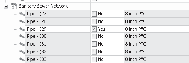
On the Pipe Networks tab, locate the entry for Pipe A in the Storm Drainage Network.
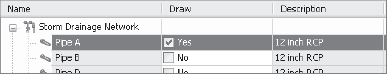
In the row for Pipe A, check the Draw box. The Draw column now says Yes, as shown in Figure 13.18.
In the row for Pipe A, check the Style Override box. The Pick Pipe Style box will appear.
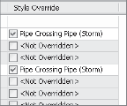
Use the pull-down list to choose the Pipe Crossing Pipe (Storm) style. Click OK.
Repeat steps 4 through 7 for Pipe C. The dialog should now look like Figure 13.19.
Click OK to exit the dialog.
Zoom in on the Parker Place profile view to see the two crossing pipes as shown in Figure 13.20.
From the Modify tab and Design panel on the ribbon, choose Pipe Network. The Pipe Networks contextual tab will appear. From the Network Tools panel, choose Draw Parts in Profile.
At the
Select network(s) to add to profile view or [Selected parts only]:prompt, enter S to choose selected parts only.At the
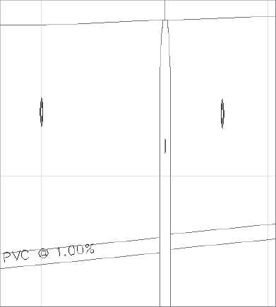
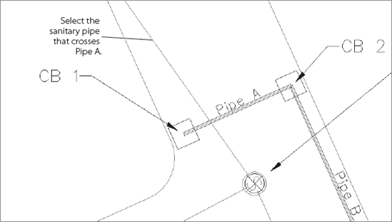
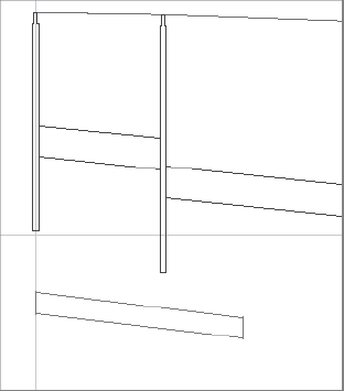
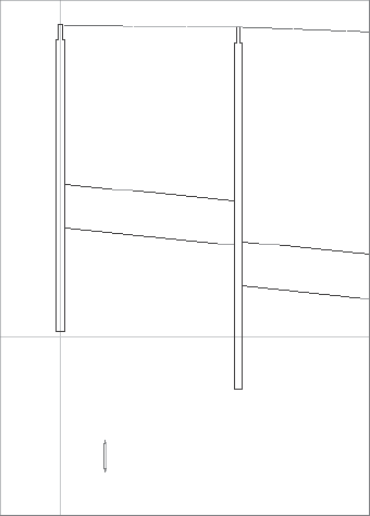
Select pipe network parts to add to profile view: prompt, in plan view, select the sanitary pipe that crosses Pipe A (see Figure 13.21). Press Enter.At the
Select profile view: prompt, select the Alignment – (Storm Drainage Network) profile view. The selected pipe will appear in profile, as shown in Figure 13.22. It will look strange until you override the style to show the pipe as a crossing.Select the Alignment – (Storm Drainage Network) profile view. The contextual tab appears. From the Modify View panel, choose Profile View Properties. The Profile View Properties dialog appears.
Switch to the Pipe Networks tab of the Profile View Properties dialog if it is not already selected.
On the Pipe Networks tab, locate the Sanitary Sewer Network category. There should be only one pipe checked for this network, as shown in Figure 13.23. (The pipe name will vary from what's shown in this figure, depending on how you drew your network.)
In the row for the sanitary pipe, check the Style Override box. The Pick Pipe Style box will appear.
Use the pull-down list to choose the Pipe Crossing Pipe (Sanitary) style. Click OK twice to exit the dialogs.
Zoom in on the Alignment – (Storm Drainage Network) profile view to see the crossing pipe, as shown in Figure 13.24.
Sometimes, drawings are crowded with many different types of annotations. Between road labels, several types of pipe networks, grading elevations, and more, it can be tricky to get all of the required information to show in a meaningful way. Tables are a method for showing pipe data in a concise list form without cluttering the plan.
The following exercise leads you through adding a pipe table for both the sanitary and storm networks:
Open
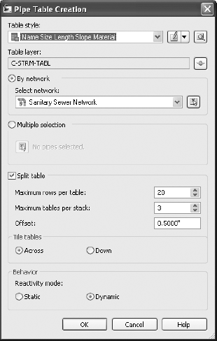
Pipes6.dwgor continue working in the drawing from the previous exercise.From the Annotate tab and Labels & Tables panel on the ribbon, choose Add Tables → Pipe Network → Add Pipe. The Pipe Table Creation dialog will appear.
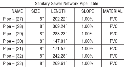
In the Pipe Table Creation dialog, make sure that the By Network radio button is selected, and Sanitary Sewer Network is chosen. Leave the remaining default settings (see Figure 13.25). Click OK.
At the
Select upper left corner: prompt, select a location in the drawing somewhere to the right of the profile views. A table will appear that looks similar to Figure 13.26. (The pipe names for your network will vary from the figure, depending on how you drew your network.)Repeat steps 2 through 4 for the Storm Drainage Network.
Whenever pipe networks are designed, it is rare that there won't be any changes. Gravity systems often require modeling to confirm that pipes meet capacity requirements, and pipes may need to be resized based on these results. Structures may need to be changed at the request of regulating agencies. Slopes may need tweaking to ensure appropriate velocity. There are many types of edits, revisions, and adjustments that will occur over the life of the design project. Civil 3D provides several ways to edit your pipe network.
You can make visual edits by stretching, moving, deleting, and spinning both pipes and structures. There are also provisions for tabular editing in Panorama, and more. No matter how you edit your pipe network, the labels, tables, and all views of your pipes and structures will change to match.
The following exercises will lead you through making several different kinds of pipe network edits and give you an opportunity to see the dynamic labeling and profiling mechanism in action.
The following exercise uses a structure grip to stretch a pipe length, change a pipe invert, and change the structure location:
Open
Pipes7.dwgor continue working in the drawing from the previous exercise.From the View tab's Viewports panel, select Viewport Configurations → 2: Horizontal. The view will split into two viewports.
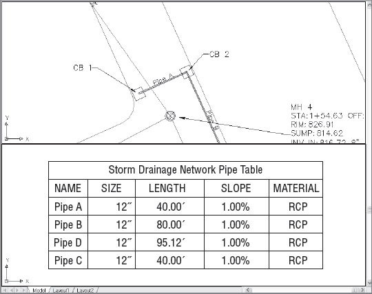
Click in the top viewport to activate it. Zoom in on Pipe A from the Storm Drainage Network in plan view.
Click in the bottom viewport to activate it. Zoom in on the Storm Drainage Network Pipe table. Your screen should look similar to Figure 13.27.
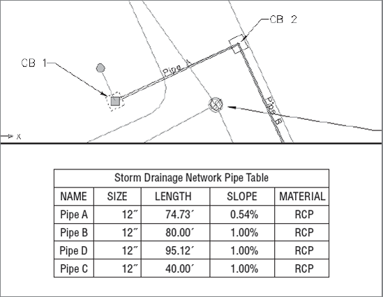
Click in the top viewport to activate it. Select CB 1. A grip will appear. Grab the grip and move the structure approximately 10′ to the left. Note that the length and slope of Pipe A has changed in the pipe table, as shown in Figure 13.28.
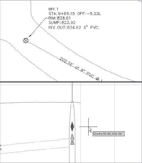
While still active in the top viewport, pan over to MH 1 so that you can clearly see the structure label.
Click in the bottom viewport to activate it. Pan over to MH 1 in profile view. Select the pipe attached to MH 1. Use the diamond-shaped grip at the pipe invert to move the pipe invert approximately 1′ higher, as shown in Figure 13.29. Note that the information in the MH 1 label in the plan changes immediately.
Click in the top viewport to active it. Select MH 1. A grip will appear. Use the grip to stretch MH 1 so that it is closer to MH 2. Note that the structure moves in the profile view, the pipe shortens, and all labels change.
Save the drawing—you will need it for the next exercise.
The following exercise uses the Swap Part function to exchange one type of pipe and structure for another:
Continue working in
Pipes7.dwg.Click in the bottom viewport to activate it. Pan over Pipe D in profile view.
Click in the top viewport to activate it. Pan over to Pipe D in plan view.
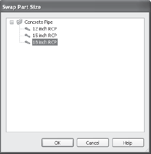
Select Pipe D. Make sure you select the pipe and not the alignment. You may find it easier to select the pipe if you freeze the alignment layer. From the contextual tab and Modify panel, choose Swap Part. The Swap Part Size dialog will appear as shown in Figure 13.30.
In the Swap Part Size dialog, choose 18 Inch RCP. Click OK.
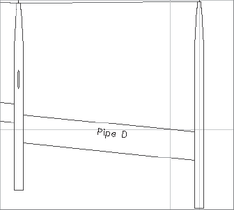
Note that the pipe style in both plan and profile views changes to reflect the larger diameter.
While still on the lower viewport, pan over to CB 4. In the upper viewport, select CB 4, and in the contextual tab and modify panel, choose Swap Part. The Swap Part Size dialog will appear. Select the Concentric Manhole. Click OK.
Note that the structure style changes in both plan and profile views to reflect the new part. Figure 13.31 shows Pipe D in profile.
Sump depth, structure insertion point, and more can be edited using the Structure Properties dialog. The following exercise has you exploring this interface and using it to adjust a sump depth:
Continue working in
Pipes7.dwg.From the View tab's Viewports panel, select Viewport Configurations → Single. The view will return to one viewport.
Pan over to MH 6. Select MH 6, right-click, and choose Structure Properties. The Structure Properties dialog will appear.
Switch to the Part Properties tab of the Structure Properties dialog if it is not already selected. Scroll down to the Sump Behavior section of the dialog. Change the sump depth from 2.000 to 0. Click OK.
Note that the sump depth has been changed to match the invert-out elevation.
Sometimes it's easier to see what's happening with your pipe network in a tabular list. The Pipe Network Vistas Panorama window allows you to see a list of pipes and/or structures for easy editing. The graphics will immediately adjust to match the model changes.
The following exercise will teach you how to adjust the sump depth of a structure using the structure properties dialog:
Continue working in
Pipes7.dwg.Pan over to the Storm Drainage Network in plan view. Select Pipe D, and from the contextual tab and Modify panel, choose Edit Pipe Network. The Network Layout Tools dialog will appear.
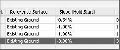
In the Network Layout Tools dialog, click the Pipe Network Vistas button. A Panorama window will appear.

Switch to the Pipes tab of the Panorama window. Scroll over to the Slope (Hold Start) column. Change the value for Pipe D from its current value to −3.00% (see Figure 13.32). Note that the pipe slope changes in profile view, and any affected labels also change to match the new slope. Dismiss the Panorama.
In this chapter, you learned some basic pipe network creation, annotation, and labeling skills. These skills will assist you in creating gravity systems, such as sanitary sewers and storm drainage. With Civil 3D pipe networks, the plan, profile, crossing, labels, and tables are linked together dynamically. This dynamic interaction reduces the possibility for errors in and omissions from pipe design and drafting.