
Although new developments in LiDAR, GPS, and aerial photography for basemap information continue to be made, almost every civil engineering project begins with a ground survey. Surveyors are responsible for locating property boundaries, existing features, utilities, surface elevations, and more.
In previous generations, the surveyors simply picked up data for a collection of points, and the linework was drawn after the data was brought into the drawing, either on paper or in CAD. As survey technology becomes more sophisticated, surveyors now have the option of field-to-finish systems, including automatic linework.
The Civil 3D survey tools are geared toward surveyors who are taking full advantage of this field-to-finish technology. This chapter focuses on the Survey Toolspace, importing a field book, and the Survey Wizard. Surveyors will also want to reference Chapter 3, "Lines and Curves," and Chapter 5, "Points." All three chapters combined provide engineers and surveyors with an introduction to the tools they need to import existing information and to prepare points for stakeout.
This chapter includes the following topics:
Setting equipment properties
Working with survey figures
Creating and editing description keys
Configuring survey network options
Importing field data
In the days of running a level or using less-sophisticated survey equipment, it was pretty common to simply dump a batch of generic points into a drawing. A CAD operator in the office would then sort through each point and figure out which dots to connect, as well as manually make adjustments to elevation, style, and so on. The CAD system had no real intelligence to offer for equipment adjustment, nor could it do automatic formatting or draw lines based on point code.
With today's equipment, things are different. There are countless manufacturers, specifications, standard field codes, and other variables, so it is important that you take time in the beginning of a project to customize the Civil 3D survey settings to your requirements.
A combination of well-crafted field standards and survey settings will produce well-formatted points and linework, as shown in Figure 4.1. This data is imported as a field book (with the filename extension .fbk), and will serve as a foundation for surface building, existing conditions plans, parceling, and all other design functions as the project evolves.
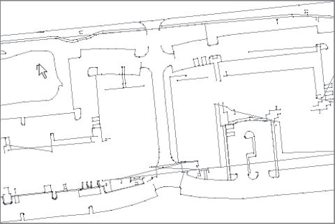
Figure 4.1. A combination of field standards and Civil 3D survey settings will automatically create properly formatted points and linework.
Every piece of survey equipment is different. Several tasks, such as traverse adjustment, may require special corrections based on the equipment properties. Civil 3D maintains an equipment database for you to store information about the tools that your crew uses for collecting data in the field. It is important to have the manufacturer's guide to each piece of equipment in hand when creating a new entry in the database.
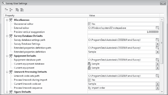
Figure 4.2. The Survey User Settings dialog provides an interface to change the default database paths and other options.
The equipment database is not drawing-specific. The database is an external file and will, therefore, be available to any project on which you are working. The storage location for this database can be changed using the Survey User Settings button on the Survey Toolspace.
The following exercise shows you how to access and modify a piece of equipment in the equipment database:
Open the
Survey.dwg, which you can download fromwww.sybex.com/go/introducingcivil3d2010. The drawing is empty.From the Home tab's Palettes panel, choose Toolspace (if it is not already visible).
From the Home tab's Palettes panel, choose Survey Toolspace. The Survey tab will be added to the Toolspace.
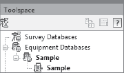
Switch to the Survey Toolspace. Click the plus sign (+) button to expand the Equipment Databases entry, and then click + again to expand the Sample equipment database as shown in Figure 4.3.
Select the Sample equipment entry, right-click, and choose Properties. The Equipment Properties dialog appears.
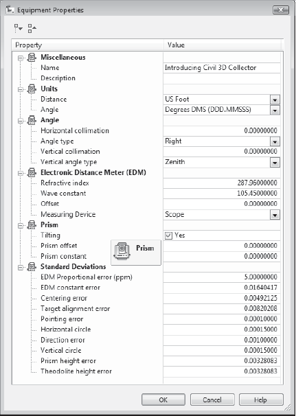
Change the name of the equipment from Sample to Introducing Civil 3D Collector in the Name Value field.
Use the pull-down button in the Value column next to Distance to change the distance units from meters to US Foot. Your dialog should now look like Figure 4.4.
Use the scroll bar to scroll down, and note each equipment option. When you're adding your specific field equipment, be sure to study the manufacturer's manual and make the necessary adjustments in this dialog. Click OK.
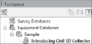
An entry appears under the Sample equipment database for Introducing Civil 3D Collector, as shown in Figure 4.5.
Survey figures are special lines drawn to connect survey data points. For example, a figure may be drawn to connect shots taken along an edge of pavement or around a property boundary. These figures can be used as foundation linework for exhibits, added to surfaces as breaklines, targeted by corridors, or used to create parcels.
When the survey crew enters specific codes into the data collector as the points are collected, these codes can be used to automatically create figures in the drawing. It is important to note that your company must have established standards and procedures for field coding before figures can be automatically created upon the import of a field book (.fbk).
The figure prefix database allows you to standardize how these figures appear in the drawing. With the appropriate figure prefix database in place, the figures will be automatically drawn on the correct layer, with the correct style applied, as shown in Figure 4.6.
The following exercise will lead you through creating a figure prefix database to standardize the styles of imported figures.

Figure 4.6. When a field book for a shopping center was imported, these curb figures were automatically created from the field codes. The figure prefix database automatically applied the appropriate style.
Continue working in the
Survey.dwgfile.Right-click the Figure Prefix Databases entry and choose New. The New Figure Prefix Database dialog will appear.
Type Introducing Civil 3D as the name for the prefix database and click OK. An entry for the new database appears.
Select the Introducing Civil 3D prefix database, right-click, and choose Edit. The Panorama window appears.
Right-click in the first Name cell, and choose New. An entry called Sample appears in the Panorama.
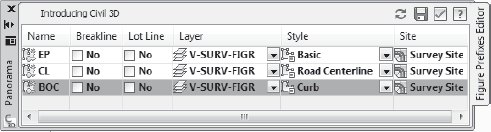
Click inside the cell that reads Sample, and change the name of the entry to EP. Use the Layer pull-down list to assign the V-SURV-FIGR layer. Use the Style pull-down list to assign the Basic style to the EP entry.
Right-click the next Name cell down from EP to create an entry for CL. Use the Layer pull-down list to assign the V-SURV-FIGR layer. Use the Style pull-down list to assign the Road Centerline style to the CL entry.
Repeat step 7 to create an entry for BOC. Use the Layer pull-down list to assign the V-SURV-FIGR layer. Use the Style pull-down list to assign the Curb style to the BOC entry. Your Panorama should now look like Figure 4.7.
Click the green checkmark in the upper-right corner of Panorama to accept the entries. A dialog will appear asking if you would like to apply changes. Click Yes.
The database is now set up and will be available when a field book is imported.
There are two different types of points in Civil 3D: coordinate geometry (COGO) points and survey points. Each type of point contains the same basic information. They each have a Number, Northing, Easting, Elevation, and Description specification. They can both be placed into groups and have point styles and label styles applied.
COGO points can be imported from external lists, created manually, moved, erased, and edited. (COGO points are discussed in more detail in Chapter 5.)
Survey points are created from field book (.fbk) files and point files.
Although the two types of points have their differences, both can be automatically processed using description keys. When a point is imported into the drawing (either through the methods discussed in Chapter 5 or when a field book is imported), it is matched up with the appropriate description key. For example, a description key for a point that is coded TREE will ensure that point has the Tree Point Style applied and is placed on the tree layer, as shown in Figure 4.8.
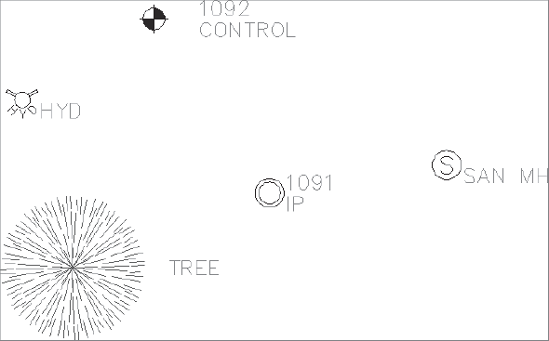
Figure 4.8. A description key automatically assigns the appropriate point style, label style, and layer based on the point code.
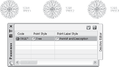
It is very common for point codes to consist of letters that identify the type of point followed by a number signifying the figure or series to which it belongs. For example, in the field book you will import later in the chapter, the edge-of-pavement points are coded EP1 and EP2, where all EP1 points are connected to create the figure that represents the north side of the road, and all EP2 points are connected to create the figure that represents the south side of the road. When creating the description key for this type of point, a wildcard (*) can be used to identify which portion of the code may vary. In this example, the code for edge-of-pavement points will be EP*, as shown in Figure 4.9.
Unlike the equipment database and the figure prefix database, description keys are drawing-specific. Once your company has established standard codes for the field crews, you need to create a description key set to match your company standard and save it in your company standard drawing template (.dwt).
In the following exercise, you'll create description keys for the four types of points that will import with the field book. These points are Edge of Pavement (EP), Back of Curb (BOC), Road Centerline (CL), and Control (CONTROL).
Continue working in the
Survey.dwgfile.Switch to the Settings tab of the Toolspace.
Locate the Description Key Sets entry under the Point tree.
Right-click Description Key Sets and choose New. The Description Key Set dialog appears.
In the Name field, change the name to Introducing Civil 3D Desc Keys. Click OK.
Click the plus sign (+) to expand the Description Key Sets list and expose the new description key that you just made.
Select Introducing Civil 3D Desc Keys, right-click, and choose Edit Keys. The Panorama window appears.
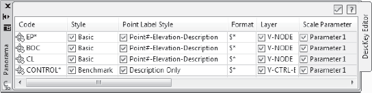
Change the name of the New Desc Key entry to EP*.
Check the box next to <default> in the Style column and click on the <default> name. The Point Style dialog will appear.
In the Point Style dialog, use the pull-down list to assign the Basic point style. Click OK.
Click on the <default> in the Point Label Style column. The Point Label Style dialog will appear.
Use the Point Label Style pull-down list to assign the Point#-Elevation-Description label style. Click OK.
Check the box in the Layer column and select the space next to the checkmark. The Layer Selection dialog will appear.
Choose V-NODE and click OK.
Right-click the EP* entry, and choose Copy.
Change the code of the new description key to BOC.
Repeat step 15, and change the code of the new description key to CL.
Right-click over the CL description key and choose New. A new description key will appear.
Change the code of the new description key to CONTROL*. Assign the Benchmark point style, the Description Only Point label style, and the V-CTRL-BMRK layer. The Panorama should now look like Figure 4.10.
Click the green checkmark in the upper-right corner to accept the description keys.
After the survey settings have been customized for equipment, figures, and point codes, you are ready to bring in the data. The Import Survey Data Wizard is designed to accept data input from a SurveyXML, point file, or a field book (.fbk) file. For the exercises in this chapter, you will import a field book via the wizard.
A field book file is not simply a list of points. The field book contains a record of how the data was collected, such as where the instrument was set up, the height of the rod, vertical and horizontal angles, and other critical information. Depending on your equipment, field standards, and procedures, a field book can also contain information about how to draw figures.
When a field book is imported into Civil 3D, the data is converted into an external survey database that will be available for use in other related drawings.
The survey database is stored in a working folder. The working folder must be set before you import survey data, and you may want to establish different working folders for different projects.
The following exercise will lead you through setting the working folder to C:Civil 3D Projects.
Continue working in the
Survey.dwgfile.Switch to the Survey tab of the Toolspace.
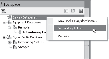
Right-click the Survey Databases entry and choose Set Working Folder (Figure 4.11). The Browse for Folder dialog will appear.
Select the Civil 3D Projects folder under your
C:drive, and click OK. The working folder is now established and all survey databases will be saved to this location.
Before you can import survey data, you must create a local survey database. You can create more than one survey database in any given working folder. For example, if a certain project were surveyed in phases, it would make sense to keep the data from those phases separate.
You will create a new survey database in the following exercise:
Continue working in the
Survey.dwgfile.From the Home tab and Create Ground Data panel on the ribbon, select Import Survey Data.
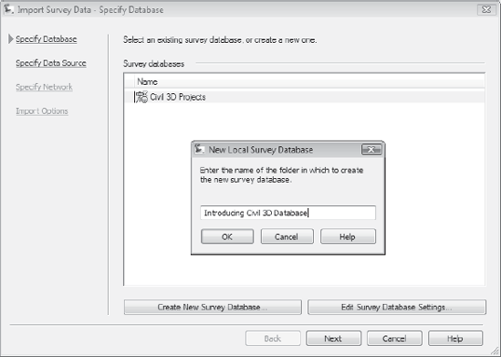
The Survey Wizard dialog will appear. Click the Create New Survey Database button. The New Local Survey Database dialog will appear.
In the dialog, type Introducing Civil 3D Survey Database. Click OK. An entry will appear in the Import Survey Data – Specify Database dialog as shown in Figure 4.12. Leave this dialog open for the next exercise.
The file type to import from is specified in the survey data source. The choices are Field Book File, Land XML File, Point File, and Points from Drawing. In this exercise, you will specify the type of file to import, which in this case is a field book file (.fbk).
Click the Next button to display the Specify Data Source dialog.
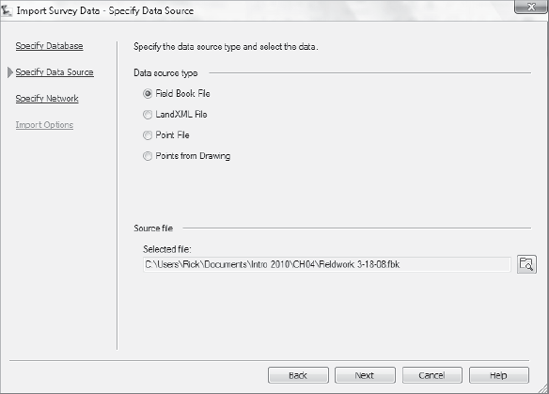
Make sure that the radio button for the Data Source Type is set to Field Book File.
In the Source File section, click the icon next to the selected file. A Search dialog will appear.
Navigate and find the file
Fieldwork 3-18-08.fbk. Click the Open button to dismiss this dialog. The full path and filename will now be populated in the Source File part of the dialog, as shown in Figure 4.13. Keep the wizard open for the next exercise.
A survey network is a collection of connected data from the field. A network can contain any of the following: setups, control points, non-control points, known directions, observations, and traverses. One survey database can contain several networks. For example, if the survey crew collects data over three days and creates three separate field books, you may want to have three networks in the project survey database.
This exercise teaches you how to create a new network via the Survey Wizard:
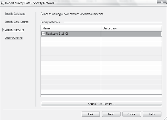
Click the Next button to display the Specify Network dialog.
Click the Create New Network button at the bottom of the dialog.
Type Fieldwork 3-18-08 in the New Network Name field as shown in Figure 4.14, and then click OK. Leave the dialog box open for the next exercise.
After the survey database has been created and a network is in place, the field book can be imported. When you import a field book, the setups, point, and figures are drawn on the screen with interactive graphics. Interactive graphics mimic the actions of the survey crew as data is processed in the drawing. When the import is complete, the data is shown on the screen, and the survey database is populated.
The next exercise leads you through importing a very simple field book:
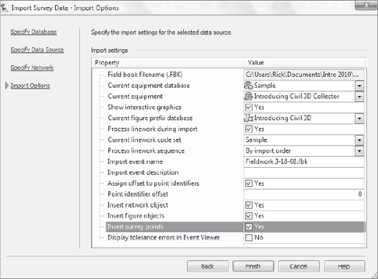
Make sure the settings match what is shown in Figure 4.15.
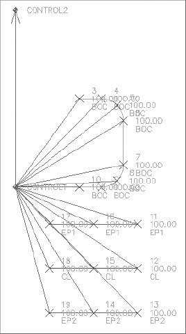
Click the Finish button and sit back while the figures and points are drawn on the screen. When they have finished, you will see the points and linework in the drawing as shown in Figure 4.16.
Zoom in on the northernmost control point. Note that the description key automatically assigned the benchmark symbol to this point based on its code of CONTROL*, as shown in Figure 4.16.
Zoom in on the edge-of-pavement and road-centerline figures. Note that the figure prefix database assigned the appropriate figure style based on the EP and CL codes.
A survey network has two fundamental components: points and figures.
Survey points, as introduced in the description key section earlier in this chapter, cannot be edited within the drawing environment. To edit a survey point, you must change the observations and data that created that point in the survey database. This may seem tedious at first glance, but it ensures that the original survey data remains intact. Survey points can be examined in Prospector, on the Survey tab under Networks, and in the drawing through tooltips and the right-click shortcut menu.
Figures are the linework created by codes and commands entered into the raw data during field collection. Figures can be edited and adjusted within the drawing environment. Figure properties can be examined on the Survey tab under Networks, and in the drawing through the right-click shortcut menu.
The following exercise will lead you through some methods for inspecting survey points and figures:
Continue working in the
Survey.dwgfile.Move your mouse over any point, and note that a tooltip appears with information about that point.
Click the plus sign (+) to expand the Survey Databases tree. Right-click Introducing Civil 3D Survey Database and click Open Survey Database. Expand the Introducing Civil 3D Survey Database tree.
Click the plus sign (+) to expand the Networks and Fieldwork 3-18-08 branches. Click the Control Points tree, select one of the control points, right-click, and choose Zoom To. Note that the drawing zooms in on the selected point.
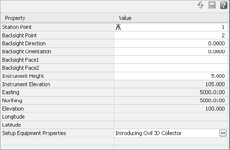
Click + to expand the Setups tree and right-click Station1, Backsight2. Select Properties and note that information regarding each setup appears in the item view (Figure 4.17).
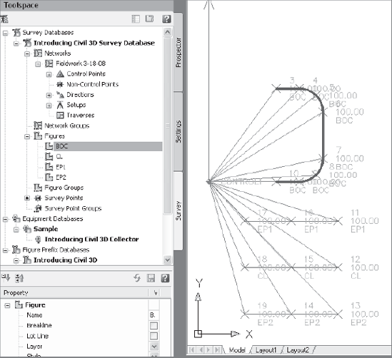
Click + to expand the Figures tree. An entry for each figure—BOC, CL, EP1, and EP2—is listed.
Select BOC and note that the BOC figure becomes highlighted in the drawing, as shown in Figure 4.18. Also note that figure information appears in the item view at the bottom of the Survey tab.
Select the Survey Points entry. Note that each survey point is listed in the item view.
You will rarely find that the first trip to the field for a project is the only fieldwork you will do for that project. Often, the first batch of data creates more questions than it answers. Once some idea of site features and topography is established, the designer will often request additional shots taken (for example, along a bordering road or to locate upstream manholes). Perhaps the first day of fieldwork alerted the crew to possible wetlands, and a few weeks later, they return to pick up the flag locations placed by the wetlands specialist.
After this new data is imported, there is always work to be done to tie the two sets of information together. Figures may need to be extended to accommodate extra points, or new figures may need to be drawn.
Survey crews will commonly return to the field to collect more data. One of the most common requests from designers is to gather more information about an existing road so that more entrance locations can be explored, or to make sure drainage has been accommodated. If the in-house crews are busy, an outside surveyor may be contracted. This surveyor may not use the same equipment as your company, or they may not be as well trained in figure creation.
The following exercise leads you through importing a field book that contains only points.
Continue working in the
Survey.dwgfile.Follow the previous exercises to invoke the Survey Wizard.
Use the same database as before (Introducing Civil 3D Survey Database).
For the Data Source, select the field book file called
AdditionalRoad.fbk.Create a new network named Fieldwork 9-18-08. Enter a network description of From outside surveyor – no linework.
Leave all the Import Options settings the way they were previously set, and click Finish.
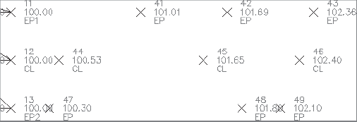
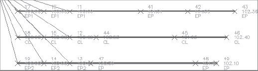
A collection of survey points appears in the drawing representing EP and CL, as shown in Figure 4.19.
There are often occasions where you need to draw new figures. Perhaps you have legacy projects where the data was collected before your crew learned how to draw figures in the field, or before your standards were in place. Maybe you receive a batch of data from an outside surveyor who doesn't use your codes. Sometimes you might find it useful to draw a figure that doesn't follow your company standards and, therefore, must be hand-drawn.
Survey figures can be created by right-clicking the figure name in the Toolspace and choosing the option to create figures from objects.
If you find an error in a figure, it might be best to make the adjustments to the field book data. If that isn't possible, figures can be edited using many of the Feature Line tools, which can be found on the Feature Line options on the Home tab and Create Design panel.
In the following exercise, you'll create figures (lines) to connect the new survey points that represent the edge of pavement and road centerline:
Continue working in the
Survey.dwgfile.In the Survey toolspace, click the plus sign (+) to expand the Figures tree.
Right-click Figures and choose Modify Figure → Begin New Figure.
At the
Enter Figure Name:prompt, type EP3 and then press Enter.At the
Specify first vertex or [Point]:prompt, type P and then press Enter.At the
Enter Point Identifier:prompt, type 43 and then press Enter.At the
Select entry [Point/Angle/Azimuth/Bearing/Deflection/Curve/Done]:prompt, type P and then press Enter.At the
Specify vertex or [Point]:prompt, type P and then press Enter.At the
Enter Point Identifier:prompt, type 42 and then press Enter. A preview of the EP3 figure is drawn between points 43 and 42, as shown in Figure 4.20.Repeat steps 8 and 9 for points 41 and 11. Press Enter to leave the point entry portion of the command.
At the
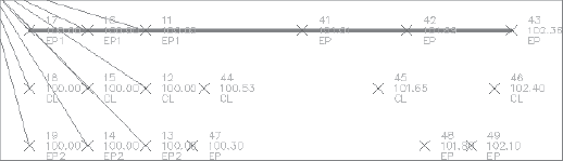
Select entry[Point/Angle/Azimuth/Bearing/DEflection/Right-turn/CUrve/CLose/DOne>:prompt, type DO and then press Enter. Although the figure has been created in the survey database, it has not yet been drawn in the drawing.On the Survey tab of the Toolspace, right-click Figures and choose Update Figures. The new EP3 figure is drawn, as shown in Figure 4.21. Note that the figure prefix database ensured that this EP figure was drawn with the correct style.
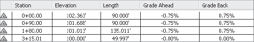
In the drawing, select the EP3 figure. Right-click and choose Elevation Editor. The Panorama window will appear.
Note in Panorama that each vertex of the figure is assigned an elevation that corresponds to the appropriate survey point. (See Figure 4.22.)
Repeat steps 3 through 9 to create new figures for the additional CL and EP points. The end result will look like Figure 4.23.

In this chapter, you were introduced to a just a few of the tools available for surveyors. First, settings must be established for equipment and field codes. Next, a file location for the survey database is chosen so that the field book can be imported to populate the database with information from the survey crew. After this data has been brought into Civil 3D, the data can be adjusted, refined, and used as a basis to launch the balance of the project.
It is important to remember that tools such as figure prefixes and description keys cannot be used until your company has well-established standards. The survey crew must use standard field codes and be well-versed in using their equipment to collect data properly for figure creation.
Inside the office, your company must also have established a Civil 3D template that contains the appropriate layers, blocks, point styles, figure styles, label styles, description keys, and other fundamental elements. An equipment database and a figure prefix database are also critical.
Although it may seem overwhelming at first, after the standards are in place, much of the tedious manual drafting that was once necessary to draw survey linework is minimized.