Two-Dimensional Vectors in Engineering |
CHAPTER 4 |
The applications of two-dimensional vectors in engineering are introduced in this chapter. Vectors play a very important role in engineering. The quantities such as displacement (position), velocity, acceleration, forces, electric and magnetic fields, and momentum have not only a magnitude but also a direction associated with them. To describe the displacement of an object from its initial point, both the distance and direction are needed. A vector is a convenient way to represent both magnitude and direction and can be described in either a Cartesian or a polar coordinate system (rectangular or polar forms).
For example, an automobile traveling north at 65 mph can be represented by a two-dimensional vector in polar coordinates with a magnitude (speed) of 65 mph and a direction along the positive y-axis. It can also be represented by a vector in Cartesian coordinates with an x-component of zero and a y-component of 65 mph. The tip of the one-link and two-links planar robots introduced in Chapter 3 will be represented in this chapter using vectors both in Cartesian and polar coordinates. The concepts of unit vectors, magnitude, and direction of a vector will be introduced.
4.1 INTRODUCTION
Graphically, a vector ![]() or simply
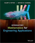
or simply ![]() with the initial point O and the final point P can be drawn as shown in Fig. 4.1. The magnitude of the vector is the distance between points O and P (magnitude = P) and the direction is given by the direction of the arrow or the angle θ in the counterclockwise direction from the positive x-axis as shown in Fig. 4.1. The arrow above P indicates that P is a vector. In many engineering books, the vectors are also written as a boldface P.
with the initial point O and the final point P can be drawn as shown in Fig. 4.1. The magnitude of the vector is the distance between points O and P (magnitude = P) and the direction is given by the direction of the arrow or the angle θ in the counterclockwise direction from the positive x-axis as shown in Fig. 4.1. The arrow above P indicates that P is a vector. In many engineering books, the vectors are also written as a boldface P.
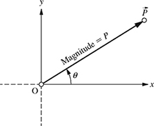
Figure 4.1 A representation of a vector.
4.2 POSITION VECTOR IN RECTANGULAR FORM
The position of the tip of a one-link robot represented as a 2-D vector ![]() (Fig. 4.2) can be written in rectangular form as
(Fig. 4.2) can be written in rectangular form as
![]()
where ![]() is the unit vector in the x-direction and
is the unit vector in the x-direction and ![]() is the unit vector in the y-direction as shown in Fig. 4.2. Note that the magnitude of the unit vectors is equal to 1. The x- and y-components, Px and Py, of the vector
is the unit vector in the y-direction as shown in Fig. 4.2. Note that the magnitude of the unit vectors is equal to 1. The x- and y-components, Px and Py, of the vector ![]() are given by
are given by
Px = P cos θ
Py = P sin θ.
Figure 4.2 One-link planar robot as a position vector in Cartesian coordinates.
4.3 POSITION VECTOR IN POLAR FORM
The position of the tip of a one-link robot represented as a 2-D vector ![]() (Fig. 4.2) can be also be written in polar form as
(Fig. 4.2) can be also be written in polar form as
![]()
where P is the magnitude and θ is the angle or direction of the position vector ![]() , and can be obtained from the Cartesian components Px and Py as
, and can be obtained from the Cartesian components Px and Py as
![]()
θ = atan2(Py, Px).
The length (magnitude) of a one-link robot shown in Fig. 4.2 is given as P = 0.5 m and the direction is θ = 30°. Find the x- and y-components Px and Py and write ![]() in rectangular vector notation.
in rectangular vector notation.
Solution
The x- and y-components Px and Py are given by
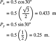
Therefore, the position of the tip of the one-link robot can be written in vector form as
![]()
The length of a one-link robot shown in Fig. 4.2 is given as ![]() and the direction is θ = 135°. Find the x- and y-components Px and Py and write
and the direction is θ = 135°. Find the x- and y-components Px and Py and write ![]() in vector notation.
in vector notation.
Solution
The x- and y-components Px and Py are given by
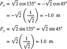
Therefore, the position of the tip of the one-link robot can be written in vector form as
![]()
The x- and y-components of the one-link robot are given as ![]() m and
m and ![]() m, as shown in Fig. 4.3. Find the magnitude (length) and direction of the robot represented as a position vector
m, as shown in Fig. 4.3. Find the magnitude (length) and direction of the robot represented as a position vector ![]() .
.
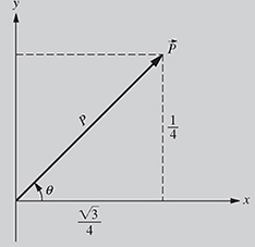
Figure 4.3 One-link planar robot for Example 4-3.
Solution
The length (magnitude) of the one-link robot is given by

and the direction θ is given by

Therefore, the position of the one-link robot ![]() can be written in polar form as
can be written in polar form as
![]() .
.
The position of the tip can also be written in Cartesian coordinates as
![]() .
.
A person pushes down on a vacuum cleaner with a force of F = 20 lb at an angle of −40° relative to ground, as shown in Fig. 4.4. Determine the horizontal and vertical components of the force.

Solution
The x- and y-components of the force are given by

Therefore, ![]() .
.
4.4 VECTOR ADDITION
The sum of two vectors ![]() and
and ![]() is a vector
is a vector ![]() written as
written as
Vectors can be added graphically or algebraically. Graphically, the addition of two vectors can be obtained by placing the initial point of ![]() on the final point of
on the final point of ![]() and then drawing a line from the initial point of
and then drawing a line from the initial point of ![]() to the final point of
to the final point of ![]() , forming a triangle as shown in Fig. 4.5.
, forming a triangle as shown in Fig. 4.5.

Figure 4.5 Graphical addition of two vectors.
Algebraically, the addition of two vectors given in equation (4.1) can be carried out by adding the x- and y-components of the two vectors. Vectors ![]() and
and ![]() can be written in Cartesian form as
can be written in Cartesian form as
Substituting equations (4.2) and (4.3) into equation (4.1) gives
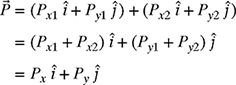
where Px = Px1 + Px2 and Py = Py1 + Py2. Therefore, addition of vectors algebraically amounts to adding their x- and y-components.
4.4.1 Examples of Vector Addition in Engineering
A two-link planar robot is shown in Fig. 4.6. Find the magnitude and angle of the position of the tip of the robot if the length of the first link ![]() m, the length of the second link P2 = 0.5 m, θ1 = 45°, and θ2 = −15°. In other words, write
m, the length of the second link P2 = 0.5 m, θ1 = 45°, and θ2 = −15°. In other words, write ![]() in polar coordinates.
in polar coordinates.
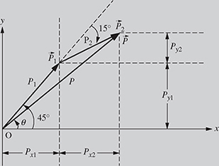
Figure 4.6 Position of two-link robot using vector addition.
Solution
The x- and y-components of the first link of the planar robot ![]() can be written as
can be written as

Therefore, ![]() . Similarly, the x- and y-components of the second link
. Similarly, the x- and y-components of the second link ![]() can be written as
can be written as
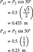
Therefore, ![]() . Finally, since
. Finally, since ![]() ,
,
![]()
The magnitude and direction of the vector ![]() are given by
are given by

Therefore, ![]() .
.
A sinusoidal current is flowing through the RL circuit shown in Fig. 4.7. The voltage phasors (vector used to represent voltages and currents in AC circuits) across the resistor R = 20 Ω and inductor L = 100 mH are given as ![]() and
and ![]()
![]() , respectively. If the total voltage phasor
, respectively. If the total voltage phasor ![]() across R and L is
across R and L is ![]()
![]() , find the magnitude and phase (angle) of
, find the magnitude and phase (angle) of ![]() .
.

The x- and y-components of the voltage phasor ![]() are given by
are given by

Therefore, ![]() . Similarly, the x- and y-components of the voltage phasor
. Similarly, the x- and y-components of the voltage phasor ![]() are given by
are given by

Therefore, ![]() . Finally, since
. Finally, since ![]() ,
,
![]()
Thus, the magnitude and phase of the total voltage phasor ![]() are given by
are given by

Therefore, ![]() .
.
A ship travels 200 miles at 45° northeast, then 300 miles due east as shown in Fig. 4.8. Find the resulting position of the ship.
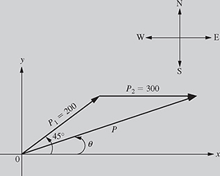
Solution The x- and y-components of the position vector ![]() are given by
are given by

Therefore, ![]() mi. Similarly, the x- and y-components of the position vector
mi. Similarly, the x- and y-components of the position vector ![]() are given by
are given by
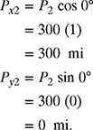
Therefore, ![]() . Finally, since
. Finally, since ![]() ,
,
![]()
Thus, the distance and direction of the ship after traveling 200 miles northeast and then 300 miles east are given by
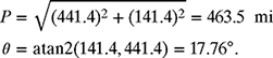
Therefore, ![]() miles. In other words, the ship is now located at 463.5 miles, 17.76° northeast from its original location.
miles. In other words, the ship is now located at 463.5 miles, 17.76° northeast from its original location.
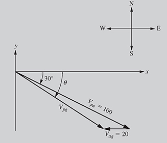
Relative Velocity: An airplane is flying at an air speed of 100 mph at a heading of 30° southeast, as shown in Fig. 4.9. If the velocity of the wind is 20 mph due west, determine the resultant velocity of the plane with respect to the ground.
Solution
The x- and y-components of the velocity of the plane relative to air, ![]() , are given by
, are given by
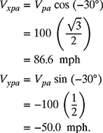
Therefore, ![]() . Similarly, the x- and y-components of the velocity of air (wind) relative to ground
. Similarly, the x- and y-components of the velocity of air (wind) relative to ground ![]() are given by
are given by

Therefore, ![]() mph. Finally, the velocity of the plane relative to ground
mph. Finally, the velocity of the plane relative to ground ![]() is given by
is given by
![]()
Thus, the speed and direction of the airplane relative to ground are given by

Therefore, ![]() .
.
Note: The velocity of the airplane relative to ground can also be found using the laws of cosines and sines discussed in Chapter 3. Using the triangle shown in Fig. 4.10, the speed of the airplane relative to ground can be determined using the law of cosines as
![]()

Figure 4.10 The triangle to determine the speed and direction of the plane.
Therefore, Vpg = 83.28 mph. Also, using the law of sines, the angle α can be found as
![]()
Therefore, ![]() and the value of α = 6.896°. The direction of the velocity of the airplane relative to ground can now be found as θ = 30 + α = 36.89°. The velocity of the plane relative to ground is, therefore, given as
and the value of α = 6.896°. The direction of the velocity of the airplane relative to ground can now be found as θ = 30 + α = 36.89°. The velocity of the plane relative to ground is, therefore, given as
![]() .
.
Note that while this geometric approach works fine when adding two vectors, it becomes unwieldy when adding three or more vector quantities. In such cases, the algebraic approach is preferable.
Static Equilibrium: A 100 kg object is hanging from two cables of equal length as shown in Fig. 4.11. Determine the tension in each cable.

Solution
The free-body diagram (FBD) of the system shown in Fig. 4.11 can be drawn as shown in Fig. 4.12.
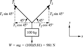
Figure 4.12 Free-body diagram of the system shown in Fig. 4.11.
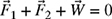
It is assumed that the system shown in Fig. 4.11 is in static equilibrium (not accelerating), and therefore the sum of all the forces are equal to zero (Newton's first law), i.e.,
![]()
or
The x- and y-components of the tension ![]() are given by
are given by

Therefore, ![]() N. Similarly, the x- and y-components of the tension
N. Similarly, the x- and y-components of the tension ![]() and weight
and weight ![]() are given by
are given by

Therefore, ![]() N and
N and ![]() N. Substituting
N. Substituting ![]() ,
, ![]() , and
, and ![]() into equation (4.4) gives
into equation (4.4) gives
![]()
In equation (4.5), the x-component is the sum of the forces in the x-direction and the y-component is the sum of forces in the y-direction. Since the right-hand side of equation (4.5) is zero, the sum of forces in the x- and y-directions are zero, or ∑Fx = 0 and ∑Fy = 0. Therefore,
and,
Adding equations (4.6) and (4.7) gives ![]() or T2 = 693.7 N. Also, from equation (4.6), T2 = T1. Therefore, both cables have the same tension, that is, T1 = T2 = 693.7 N.
or T2 = 693.7 N. Also, from equation (4.6), T2 = T1. Therefore, both cables have the same tension, that is, T1 = T2 = 693.7 N.
Static Equilibrium: A 100 kg television is loaded onto a truck using a ramp at a 30° angle. Find the normal and frictional forces on the TV if it is left sitting on the ramp.

Solution
The free-body diagram (FBD) of the TV sitting on the ramp as shown in Fig. 4.13 is given in Fig. 4.14 where W = 100 × 9.81 = 981 Newton.

Figure 4.14 Free-body diagram of a TV on the 30° ramp.
Note that we are using the rotated axes to simplify the computation below. It is assumed that the system shown in Fig. 4.13 is in static equilibrium; therefore, the sum of all the forces is equal to zero (Newton's first law):
The x- and y-components of the TV weight ![]() are given by
are given by

Therefore, ![]() N. Similarly, the x- and y-components of the frictional force
N. Similarly, the x- and y-components of the frictional force ![]() and normal force
and normal force ![]() are given by
are given by

Therefore, ![]() N and
N and ![]() N. Substituting
N. Substituting ![]() ,
, ![]() , and
, and ![]() into equation (4.8) gives
into equation (4.8) gives
Equating the x- and y-components in equation (4.9) to zero yields
![]()
![]()
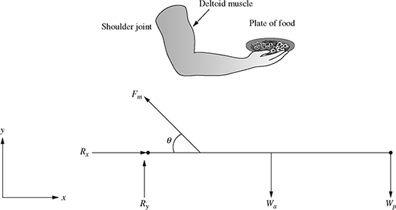
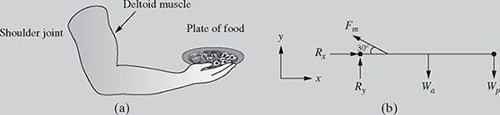
A waiter extends his arm to hand a plate of food to his customer. The free-body diagram is shown in Fig. 4.15, where Fm = 400 N is the force in the deltoid muscle, Wa = 40 N is the weight of the arm, Wp = 20 N is the weight of the plate of food, and Rx and Ry are the x- and y-components of the reaction forces at the shoulder.
(a) Using the x-y coordinate system shown in Fig. 4.15, write the muscle force ![]() , the weight of the arm
, the weight of the arm ![]() , and the weight of the plate
, and the weight of the plate ![]() in standard vector notation (i.e., using unit vectors i and j).
in standard vector notation (i.e., using unit vectors i and j).
(b) Determine the values of Rx and Ry required for static equilibrium: ![]()
![]() . Also compute the magnitude and direction of
. Also compute the magnitude and direction of ![]() .
.
(a) The x- and y-components of the deltoid muscle force ![]() are given by
are given by
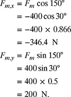
Therefore, ![]() . Similarly, the x- and y-components of the weight of the arm
. Similarly, the x- and y-components of the weight of the arm ![]() and weight of the plate Wp are given by
and weight of the plate Wp are given by

Therefore, ![]() and
and ![]() .
.
(b) It is assumed that the system shown in Fig. 4.15 is in static equilibrium; therefore, the sum of all the forces is equal to zero (Newton's first law):

Equating the x- and y-components in equation (4.10) to zero yields

Therefore, ![]() . The magnitude and direction of
. The magnitude and direction of ![]() can be obtained as
can be obtained as

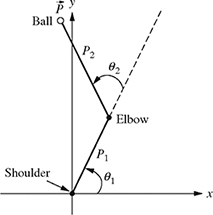
Using motion capture, the positions of each arm segment are measured while a person throws a ball. The length from shoulder to elbow (P1) is 12 in. and the length from elbow to hand (P2) is 18 in. The angle θ1 is 45° and θ2 is 20°.
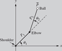
Figure 4.16 Position of the arm throwing a ball.
(a) Using the x-y coordinate system shown in Fig. 4.16, write the position of the ball ![]() in the standard vector notation.
in the standard vector notation.
(b) Find the magnitude and direction of ![]() .
.
Solution
(a) The x- and y-components of the position ![]() are given by
are given by

Therefore, ![]() in. Similarly, the x- and y-components of the position
in. Similarly, the x- and y-components of the position ![]() are given by
are given by

Therefore, ![]() in. The position of the arm
in. The position of the arm ![]() can now be found in standard vector notation by adding vectors
can now be found in standard vector notation by adding vectors ![]() and
and ![]() as
as

(b) The magnitude of the position ![]() is given by
is given by

The direction of position ![]() is given by
is given by

Therefore, the vector ![]() can be written in the polar form as
can be written in the polar form as ![]() in.
in.
PROBLEMS
-
4-1. Locate the tip of a one-link robot of 12 in. length as a 2-D position vector with a direction of 60°. Draw the position vector and find its x- and y-components. Also, write
 in both its rectangular and polar forms.
 -
4-2. Locate the tip of a one-link robot of 1.5 ft length as a 2-D position vector with a direction of −30°. Draw the position vector and find its x- and y-components. Also, write
 in both its rectangular and polar forms.
 -
4-3. Locate the tip of a one-link robot of 1 m length as a 2-D position vector with a direction of 120°. Draw the position vector and find its x- and y-components. Also, write
 in both its rectangular and polar forms.
 -
4-4. Locate the tip of a one-link robot of 2 m length as a 2-D position vector with a direction of −135°. Draw the position vector and find its x- and y-components. Also, write
 in both its rectangular and polar forms.
 -
4-5. The tip of a one-link robot is represented as a position vector
 as shown in Fig. P4.5. Find the x- and y-components of the vector if the length of the link is P = 10 in. and θ = 30°. Also, write the vector
  in rectangular and polar form.
Figure P4.5 A one-link robot represented in polar coordinates.
-
4-7. Repeat problem P4-5 if P = 15 cm and θ = −120°.
-
4-8. Repeat problem P4-5 if P = 6 in. and θ = −60°.
-
4-9. The x- and y-components of a vector
 shown in Fig. P4.9 are given as Px = 2 cm and Py = 3 cm. Find the magnitude and direction, and write the vector
  in its rectangular and polar forms.
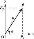
-
4-10. The x- and y-components of a vector
 shown in Fig. P4.10 are given as Px = 3 in. and Py = −4 in. Find the magnitude and direction, and write the vector
  in its rectangular and polar forms.
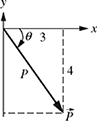
-
4-11. The x- and y-components of a vector
 shown in Fig. P4.11 are given as Px = −1.5 cm and Py = 2 cm. Find the magnitude and direction, and write the vector
  in its rectangular and polar forms.
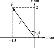
-
4-12. The x- and y-components of a vector
 shown in Fig. P4.12 are given as Px = −1 in. and Py = −2 in. Find the magnitude and direction, and write the vector
  in its rectangular and polar forms.
-
4-13. A state trooper investigating an accident pushes a wheel (shown in Fig. 4.13) to measure skid marks. If a trooper applies a force of 20 lb at an angle of θ = 45°, find the horizontal and vertical forces acting on the wheel.

-
4-14. Repeat problem P4-13 if the trooper is applying a force of 10 lb at an angle of θ = 60°.
-
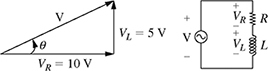
4-15. In a RL circuit, the voltage across the inductor VL leads the voltage across the resistor by 90° as shown in Fig. P4.15. If VR =10 V and VL = 5 V, find the total voltage
 .
.
-
4-16. Repeat problem P4-15 if VR =10 V and VL = 15 V.
-
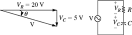
4-17. In an RC circuit, the voltage across the capacitor VC lags the voltage across the resistor by −90° as shown in Fig. P4.17. If VR = 20 V and VC = 5 V, find the total voltage
 .
.
-
4-18. Repeat problem P4-17 if VR = 10 V and VL = 20 V.
-
4-19. In an electrical circuit, voltage
 lags voltage
  by 30° as shown in Fig. P4.19.
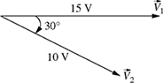
Figure P4.19 Voltages
and for problem P4-19.Find the sum of the two voltages; in other words, find
 .
. -
4-20. In an electrical circuit, voltage
 leads voltage
  by 60° as shown in Fig. P4.20. Find the sum of the two voltages; in other words, find
  .
.
-
4-21. An airplane travels at a heading of 45° northeast with an air speed of 300 mph. The wind is blowing at 30° southeast at a speed of 40 mph as shown in Fig. P4.21. Find the speed (magnitude of the velocity
 ) and the direction θ of the plane relative to the ground using vector addition. Check your answer by finding the magnitude and direction using the laws of sines and cosines.
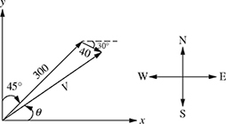
-
4-22. An airplane travels at a heading of −60° with an air speed of 500 mph. The wind is blowing at 30° at a speed of 50 mph as shown in Fig. P4.22. Find the speed (magnitude of the velocity
 ) and the direction θ of the plane relative to the ground using vector addition. Check your answer by finding the magnitude and direction using the laws of sines and cosines.
-
4-23. A large barge is crossing a river at a heading of 30° northwest with a speed of 15 mph against the water as shown in Fig. P4.23. The river flows due east at a speed of 5 mph.
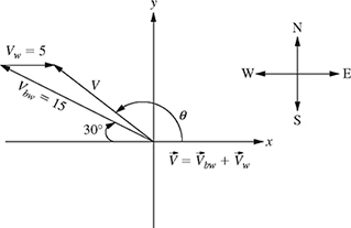
Figure P4.23 A barge crossing a river against the current.
(a) Calculate the resultant velocity
 of the barge using vector addition (use the
  and
and  notation).
(b) Determine the magnitude and direction of
 .
.(c) Repeat part (b) using the laws of sines and cosines.
-
4-24. A ship is crossing a river at a heading of −150° with a speed of VSW = 30 mph against the water as shown in Fig. P4.24. The river is flowing in the direction of 135° with a speed of VW = 10 mph.

Figure P4.24 A ship crossing a river against the current.
(a) Calculate the resultant velocity
 of the ship using vector addition (use the
  and
and  notation).
(b) Determine the magnitude and direction of
 .
.(c) Repeat part (b) using the laws of sines and cosines.
-
4-25. A boat moves diagonally across a river at a heading of 45° southwest and at a water speed of Vbw = 12 mph as shown in Fig 4.25. The river flows due east at a speed of Vw = 4 mph.

Figure P4.25 A boat moving diagonally across a river.
(a) Determine the resultant velocity
 of the boat, which is given by
  . In so doing, express all vectors using standard vector notation (i.e., using unit vectors
  and
and  ). Given your result for
  , also determine the magnitude V and direction θ.
(b) Repeat part (a) using the laws of sines and cosines.
-
4-26. A two-link planar robot is shown in Fig. P4.26.
(a) Calculate the position of the tip
 of the planar robot using vector addition (use the
  and
and  notation).
(b) Determine the magnitude and direction of the position of the robot tip. In other words, write vector
 in the polar form.
(c) Repeat part (b) using the laws of sines and cosines.

-
4-27. A two-link planar robot is shown in Fig. P4.27.
(a) Calculate the position of the tip
 of the planar robot using vector addition (use the
  and
and  notation).
(b) Determine the magnitude and direction of
 .
.(c) Repeat part (b) using the laws of sines and cosines.

-
4-28. A two-link planar robot is shown in Fig. P4.28.
(a) Calculate the position of the tip
 of the planar robot using vector addition (use the
  and
and  notation).
(b) Determine the magnitude and direction of the position of the robot tip. In other words, write vector
 in the polar form.
(c) Repeat part (b) using the laws of sines and cosines.

-
4-29. A two-link planar robot is shown in Fig. P4.29.
(a) Calculate the position of the tip
 of the planar robot using vector addition (use the
  and
and  notation).
(b) Determine the magnitude and direction of
 .
.(c) Repeat part (b) using the laws of sines and cosines.
-
4-30. A 200 lb weight is suspended by two cables as shown in Fig. P4.30.
(a) Determine the angle α.
(b) Express
 and
and  in rectangular vector notation and determine the values of T1 and T2 required for static equilibrium (i.e.,
 ).
). -
4-31. A weight of 100 kg is suspended from the ceiling by cables that make 30° and 60° angles with the ceiling as shown in Fig. P4.31. Assuming that the weight is not moving
 , find the tensions
  and
and  .
.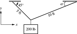
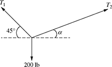
Figure P4.30 A weight suspended from two cables for problem P4-30.

Figure P4.31 A weight suspended from two cables for problem P4-31.
-
4-32. A vehicle weighing 10 kN is parked on an inclined driveway, as shown in Fig. P4.32.
(a) Determine the angle θ.
(b) Express the normal force
 , the frictional force
  , and the weight
  in rectangular vector notation.
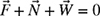
(c) Determine the values of F and N required for equilibrium (i.e.,

 ).
).
Figure P4.32 A vehicle parked on an inclined driveway for problem P4-32.
-
4-33. A vehicle weighing 2000 lb is parked on an inclined driveway, as shown in Fig. P4.33.
(a) Determine the angle θ.
(b) Express the normal force
 , the frictional force
  , and the weight in rectangular vector notation.
(c) Determine the values of F and N required for equilibrium (i.e.,


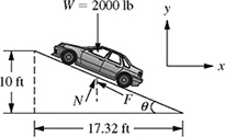
Figure P4.33 A vehicle parked on an inclined driveway for problem P4-33.
-
4-34. A crate of weight W = 100 lb sits on a ramp oriented at 27 degrees relative to ground, as shown in Fig. P4.34. The free-body diagram showing the external forces is also shown in Fig. P4.34.
(a) Using the x-y coordinate system shown in Fig. P4.34, write the friction force
 and the normal force
  in rectangular vector notation (i.e., in terms of unit vectors
  and
and  ).
).(b) Determine the values of F and N required for static equilibrium; in other words, find the values of F and N if
 .
.
-
4-35. A 500 N television sits on an inclined ramp, as shown in Fig. P4.35. The free-body diagram showing the external forces is also shown in Fig. P4.35.
(a) Determine the angle θ.
(b) Using the x-y coordinate system shown in Fig. P4.35, write the friction force
 and the normal force
  in rectangular vector notation (i.e., in terms of unit vectors
  and
and  ).
).(c) Determine the values of F and N required for static equilibrium; in other words, find the values of F and N if
 .
.
Figure P4.35 A crate resting on an inclined ramp for problem P4-35.
-
4-36. A two-bar truss supports a weight of W = 750 lb as shown in Fig. P4.36. The truss is constructed such that θ = 38.7°.
(a) Using the positive x-y coordinate system shown in Fig. P4.36, write the forces
 ,
,  , and weight
  in rectangular vector notation (i.e., in terms of unit vectors
  and
and  ).
).(b) Determine the values of F1 and F2 such that
 .
. -
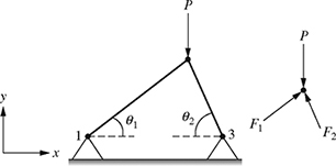
4-37. A two-bar truss is subjected to a vertical load P = 346 lb, as shown in Fig. P4.37. The truss is constructed such that θ1 = 39.6° and θ2 = 62.4°.
(a) Using the positive x-y coordinate system shown in Fig. P4.37, write the forces
 ,
,  , and
, and  in rectangular vector notation (i.e., in terms of unit vectors
  and
and  ).
).(b) Determine the values of F1 and F2 such that
 .
.Figure P4.36 A weight supported by a two-bar truss.
-
4-38. A force F = 100 N is applied to a two-bar truss as shown in Fig. P4.38. Express forces
 ,
,  , and
, and  in terms of unit vectors
  and
and  and determine the values of F1 and F2 such that
  .
.
-
4-39. A block of weight W = 125 lb rests on a hinged shelf as shown in Fig. P4.39. The shelf is constructed such that θ = 41.7°.
(a) Using the positive x-y coordinate system shown in Fig. P4.39, write the forces
 ,
,  , and weight
  in rectangular vector notation (i.e., in terms of unit vectors
  and
and  ).
).(b) Determine the values of F1 and F2 such that
 .
.
-
4-40. A waiter extends his arm to hand a plate of food to his customer. The free-body diagram is shown in Fig. P4.40 where
 is the force in the deltoid muscle, Wa = 35 N is the weight of the arm, Wp = 15 N is the weight of the plate of food, Rx and Ry are the x- and y-components of the reaction forces at the shoulder, and θ = 45°.
Figure P4.40 Waiter handing a plate to a customer.
(a) Using the x-y coordinate system shown in Fig. P4.40, write the deltoid muscle force
 , the weight of the arm
  , and the weight of the plate
  in the standard vector notation (i.e., using unit vectors i and j).
(b) Determine the values of Rx and Ry required for static equilibrium:
 . Also compute the magnitude and direction of
  .
. -
4-41. Repeat problem P4-40 if Fm = 50 lb, Wa = 7 lb, Wp = 3 lb, and θ = 30°.
-
4-42. Using motion capture, the positions
 and
and  of each arm segment are measured while a person throws a ball. The length from shoulder to elbow (P1) is 10 in. and the length from elbow to the hand holding the ball (P2) is 13 in. The angle θ1 is 60° and θ2 is 65°.
(a) Using the x-y coordinate system shown in Fig. P4.42, write the position of the ball
 in standard vector notation.
(b) Determine both the magnitude and direction of
 .
.
-
4-43. Repeat problem P4-42 if P1 = 1 ft, P2 = 1.5 ft, θ1 = 45°, and θ2 is 60°.