Complex Numbers in Engineering |
CHAPTER 5 |
5.1 INTRODUCTION
Complex numbers play a significant role in all engineering disciplines, and a good understanding of this topic is necessary. However, it is especially important for the electrical engineer to master this topic. Although imaginary numbers are not commonly used in daily life, in engineering and physics they are in fact used to represent physical quantities such as impedance of RL, RC, or RLC circuit.
Complex numbers are numbers that consist of two parts, one real and one imaginary. An imaginary number is the square root of a negative real number (−1). The square root of a negative real number is said to be imaginary because there is no real number that gives a negative number after it has been squared. The imaginary number ![]() is represented by the letter i by mathematicians and by almost all the engineering disciplines except electrical engineering. Electrical engineers use the letter j to represent imaginary number because the letter i is used in electrical engineering to represent current. To remove this confusion,
is represented by the letter i by mathematicians and by almost all the engineering disciplines except electrical engineering. Electrical engineers use the letter j to represent imaginary number because the letter i is used in electrical engineering to represent current. To remove this confusion, ![]() will be represented by the letter j throughout this chapter.
will be represented by the letter j throughout this chapter.
In general, imaginary numbers are used in combination with a real number to form a complex number, a + bj, where a is the real part (real number) and bj is the imaginary part (real number times the imaginary unit j). The complex number is useful for representing two-dimensional variables where both dimensions are physically significant and are represented on a complex number plane (which looks very similar to the Cartesian plane discussed in Chapter 4). On this plane, the imaginary part of the complex number is measured by the vertical axis (on the Cartesian plane, this is the y-axis) and the real number part goes on the horizontal axis (x-axis on the Cartesian plane). The one-link robot discussed in Chapter 3 could be described using a complex number where the real part would be its component in the x-direction and the imaginary part would be its component in the y-direction. Note that the example of one-link planar robot is used only to show similarities between the two-dimensional vector and the complex number. The position of the tip of the robot is generally not described by a complex number.
In many ways, operations with complex numbers follow the same rules as those for real numbers. However, the two parts of a complex number cannot be combined. Even though the parts are joined by a plus sign, the addition cannot be performed. The expression must be left as an indicated sum.
5.2 POSITION OF ONE-LINK ROBOT AS A COMPLEX NUMBER
The one-link planar robot shown in Fig. 5.1 can be represented by a complex number as
P = Px + j Py
or
P = Px + Py j,
where ![]() is the imaginary number, Px = Re(P) = l cos(θ) is the real part, and Py = Im(P) = l sin(θ) is the imaginary part of the complex number P. The numbers Px and Py are like the components of P in the x- and y-directions (analogous to a 2-D vector). Similarly, the one-link planar robot can be represented in polar form as
is the imaginary number, Px = Re(P) = l cos(θ) is the real part, and Py = Im(P) = l sin(θ) is the imaginary part of the complex number P. The numbers Px and Py are like the components of P in the x- and y-directions (analogous to a 2-D vector). Similarly, the one-link planar robot can be represented in polar form as
P = |P|∠θ,
where ![]() is the magnitude and θ = atan2(Py, Px) is the angle of the complex number P.
is the magnitude and θ = atan2(Py, Px) is the angle of the complex number P.
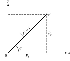
Figure 5.1 Representation of a one-link planar robot as a complex number.
Therefore,

where cos θ + j sin θ = ejθ is Euler's formula. The complex number written as in equation (5.1) is known as the exponential form of the complex number and can be used to express the cosine and sine functions. The cosine function is the real part of the exponential function and the sine function as the imaginary part of the exponential function; i.e.,
cosθ = Re(ej θ)
and
sinθ = Im(ej θ)
In summary, a point P in the rectangular plane (x-y plane) can be described as a vector or a complex number as

5.3 IMPEDANCE OF R, L, AND C AS A COMPLEX NUMBER
5.3.1 Impedance of a Resistor R
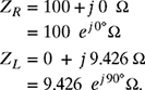
The impedance of the resistor shown in Fig. 5.2 can be written as ZR = R Ω, where R is the resistance in ohms (Ω). If R = 100 Ω, the impedance of the resistor can be written as a complex number in rectangular and polar forms as

![]()
5.3.2 Impedance of an Inductor L
The impedance of the inductor shown in Fig. 5.3 can be written as ZL = jωL Ω, where L is the inductance in henry (H) and ω = 2πf is the angular frequency in rad/s (f is the linear frequency or frequency in hertz (Hz)). If L = 25 mH and f = 60 Hz, the impedance of the inductor can be written as a complex number in rectangular and polar forms as

![]()
5.3.3 Impedance of a Capacitor C
The impedance of the capacitor shown in Fig. 5.4 can be written as ![]() , where C is the capacitance in farad (F) and ω is the angular frequency in rad/s. If C = 20 μF and f = 60 Hz, the impedance of the capacitor can be written as a complex number in rectangular form as
, where C is the capacitance in farad (F) and ω is the angular frequency in rad/s. If C = 20 μF and f = 60 Hz, the impedance of the capacitor can be written as a complex number in rectangular form as

where ![]() . The impedance of the capacitor can also be written in polar and exponential form as
. The impedance of the capacitor can also be written in polar and exponential form as
![]()
![]()
5.4 IMPEDANCE OF A SERIES RLC CIRCUIT
The total impedance of the series RLC circuit shown in Fig. 5.5 is given by
where ZR = R Ω, ZL = jωL Ω, and ![]() .
.
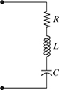
Figure 5.5 A series RLC circuit.
For the values of R = 100 Ω, L = 25 mH, C = 20 μF, and ω = 120π rad/s, the impedance of R, L, and C were calculated in Section 5.3 as

Since ZT = ZR + ZL + ZC, the total impedance of the series RLC circuit can be calculated as

Therefore, the total impedance of the series RLC circuit shown in Fig. 5.5 in rectangular form is ZT = 100 − j 123.174 Ω. The polar and exponential forms of the total impedance can be calculated from the rectangular form as
Polar Form: ZT = |ZT|∠θ, where

Therefore, ZT = 158.7 ∠−50.93°Ω.
Exponential Form: ZT = |ZT|ej θ = 158.7 e−j 50.93°Ω.
Note: The addition and subtraction of complex numbers is best done in the rectangular form. If the complex numbers are given in the polar or exponential form, they should be converted to rectangular form to carry out the addition or subtraction of these complex numbers. However, if the result is needed in the polar or exponential form, the conversion from the rectangular to polar or exponential forms is carried out as a last step.
In summary, the addition and subtraction of two complex numbers can be carried out using the following steps.
Addition of Two Complex Numbers: The addition of two complex numbers Z1 = a1 + j b1 and Z2 = a2 + j b2 can be obtained as

Therefore, the real part, a, of the addition of complex numbers, Z, is obtained by adding the real parts of the complex numbers being added, and the imaginary part of the addition of the two complex numbers is obtained by adding the imaginary parts of complex numbers being added.
Subtraction of Two Complex Numbers: Similarly, the subtraction of the two complex numbers Z1 and Z2 can be obtained as
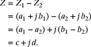
Therefore, the real part, c, of the subtraction of two complex numbers Z1 and Z2 (Z1 − Z2) is obtained by subtracting the real part a2 of complex numbers Z2 from the real part a1 of complex number Z1. Similarly, the imaginary part of the subtraction of the two complex numbers Z1 − Z2 is obtained by subtracting the imaginary part b2 of complex number Z2 from the imaginary part b1 of complex number Z1, respectively.
5.5 IMPEDANCE OF R AND L CONNECTED IN PARALLEL
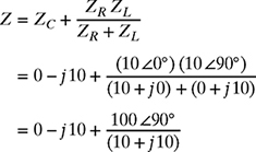
The total impedance Z of a resistor R connected in parallel with an inductor L as shown in Fig. 5.6 is given by
![]()
where ZR = R Ω and ZL = jωL Ω.

Figure 5.6 A parallel RL circuit.
For R = 100 Ω, L = 25 mH and ω = 120 π rad/s, the impedances of R and L were calculated in Section 5.3 as
Since ![]() , the total impedance of the R connected in parallel with L can be calculated as
, the total impedance of the R connected in parallel with L can be calculated as

Therefore, the total impedance of a 100 Ω resistor connected in parallel with a 25 mH inductor in the polar form is Z = 9.384 ∠84.62°Ω. The rectangular form of the total impedance can be calculated from the polar form as
![]()
Therefore, Z = 0.88 + j 9.34 Ω.
Note that the multiplication and division of complex numbers can be carried out in rectangular or polar forms. However, it will be shown in Section 5.7 that it is best to carry out these operations in polar form. If the complex numbers are given in rectangular form, they should be converted to polar form and the result of the multiplication or division is then obtained in the polar form. However, if the result is needed in rectangular form, the conversion from polar to rectangular form is carried out as a last step. The steps to carry out the multiplication and division in the polar form are explained next.
Multiplication of Complex Number in Polar Form: The multiplication of the two complex numbers Z1 = M1 ∠θ1 and Z2 = M2 ∠θ2 can be carried out as
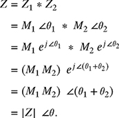
Therefore, the magnitude |Z| of the multiplication of complex numbers given in polar form is obtained by multiplying the magnitudes of complex numbers being multiplied and the angle ∠θ of the resultant is the sum of the angles of the complex numbers being multiplied. Note that this procedure is not restricted to multiplication of two numbers only; it can be used for multiplying any number of complex numbers.
Division of Complex Number in Polar Form: The division of the two complex numbers Z1 and Z2 in the polar form can be carried out as

Therefore, the magnitude |Z| of the division of two complex numbers given in polar form is obtained by dividing the magnitudes of dividend complex number Z1 by the magnitude of divisor complex number Z2. The angle ∠θ of the resultant is obtained by subtracting the angle of the divisor complex numbers Z2 from the angle of the dividend complex number Z1. Note that if the dividend or the divisor are the product of complex numbers, the product of all the dividend and the divisor complex numbers should be obtained first, and then the division of the two complex numbers should be carried out.
5.6 ARMATURE CURRENT IN A DC MOTOR
The winding of an electric motor shown in Fig. 5.7 has a resistance of R = 10 Ω and an inductance of L = 25 mH. If the motor is connected to a 110 V, 60 Hz voltage source as shown, find the current ![]() A flowing through the winding of the motor, where Z = ZR + ZL and V = 110 V.
A flowing through the winding of the motor, where Z = ZR + ZL and V = 110 V.
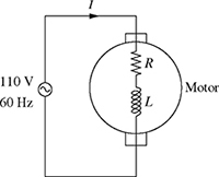
Figure 5.7 Voltage applied to a motor.
The total impedance of the winding of the motor is given as Z = ZR + ZL, where ZR = R = 10 + j 0 Ω and ZL = j ω L = 0 + j 9.426 Ω. Therefore, Z = (10 + j 0) + (0 + j 9.426) = 10 + j 9.426 Ω, and the current flowing through the winding of the motor is

Since it is easier to multiply and divide in exponential or polar forms, the current in equation (5.3) will be calculated in the polar/exponential form. Converting the numerator and denominator in equation (5.3) to exponential form yields

Therefore, the current flowing through the winding of the motor is 8.01 A. The phasor diagram (vector diagram) showing the voltage and current vectors is shown in Fig. 5.8. It can be seen from Fig. 5.8 that the current is lagging (negative angle) the voltage by 43.3°. The polar form of the current given in equation (5.4) can be converted to rectangular form as

Note: In general e± θ = cos θ ± j sin θ requires θ in radians. However, converting to radians is unnecessary for the purpose of multiplying and dividing complex numbers.

Figure 5.8 The current and voltage vector.
5.7 FURTHER EXAMPLES OF COMPLEX NUMBERS IN ELECTRIC CIRCUITS
A current, I, flowing through the RL circuit shown in Fig. 5.9 produces a voltage, V = I Z, where Z = R + j XL. Find V if I = 0.1 ∠30°A.

Solution
The impedance Z of the RL circuit can be calculated as
![]()
The voltage V = I Z = (0.1 ∠30°)(100 + j 30) V will be calculated by multiplying the two complex numbers using their rectangular forms as well as their polar/exponential forms to show that it is much easier to multiply complex numbers using the polar/exponential forms.

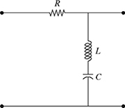
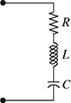
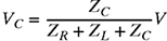
In the voltage divider circuit shown in Fig. 5.10, the impedance of the resistor is given by Z1 = R. The total impedance of the inductor and capacitor in series is given by ![]() , where
, where ![]() . Suppose R = 10, XL = 10, and XC = 20, all measured in ohms:
. Suppose R = 10, XL = 10, and XC = 20, all measured in ohms:
(a) Express the impedance Z1 and Z2 in both rectangular and polar forms.
(b) Suppose the source voltage is ![]() . Compute the voltage V1 given by
. Compute the voltage V1 given by
![]()
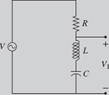
Figure 5.10 Voltage divider circuit for Example 5-2.
Solution
(a) The impedance Z1 can be written in rectangular form as
![]()
The impedance Z1 can be written in polar form as
![]()
The impedance Z2 can be written in rectangular form as
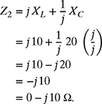
The impedance Z2 can be written in polar form as
![]()
(b)

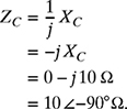
In the circuit shown in Fig. 5.11, the impedance of the various components are ZR = R, ZL = j XL, and ![]() , where
, where ![]() . Suppose R = 10, XL = 10, and XC = 10, all measured in ohms.
. Suppose R = 10, XL = 10, and XC = 10, all measured in ohms.
(a) Express the total impedance ![]() in both rectangular and polar forms.
in both rectangular and polar forms.
(b) Suppose a voltage ![]() is applied to the circuit shown in Fig. 5.11. Find the current I flowing through the circuit if I given by
is applied to the circuit shown in Fig. 5.11. Find the current I flowing through the circuit if I given by
![]()
Solution
(a) The impedance ZR can be written in rectangular and polar forms as


Figure 5.11 Total impedance of the circuit for Example 5-3.
The impedance ZL can be written in rectangular and polar forms as

The impedance ZC can be written in rectangular and polar forms as
The total impedance can now be calculated as

(b)

A sinusoidal voltage source vs = 100 cos(100 t + 45°) V is applied to a series RLC circuit. Write the voltage source vs in the exponential form.
Solution
Since cos(θ) = Re(ej θ), therefore, the voltage source vs can be written in the exponential form as
vs = Re(100 ej(100 t+45°))V.
A sinusoidal current source is = 100 sin(120 π t + 60°) mA is applied to a parallel RL circuit. Write the current source is in the exponential form.
Solution
Since sin(θ) = Im(ej θ), therefore, the current source is can be written in the exponential form as
is = Im(100 ej(120 π t+60°))mA.
5.8 COMPLEX CONJUGATE
The complex conjugate of a complex number z = a + j b is
z* = a − j b.
The multiplication of a complex number by its conjugate results in a real number that is the square of the magnitude of the complex number:
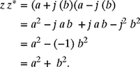
Also,
![]()
Therefore, z z* = |z|2 = a2 + b2.
Solution
The conjugate of the complex number z = 3 + j 4 is given by
z* = 3 − j 4.
Calculating z z* using the rectangular form yields

Therefore, z z* = 25. Note: ![]() . Now, calculating z z* using the polar form, we have
. Now, calculating z z* using the polar form, we have

Therefore, z z* = 25. Note that the complex conjugate of a complex number in polar form has the same magnitude as the complex number, but the angle of the complex conjugate is the negative of the angle of the complex number.
PROBLEMS
-
5-1. In the series RL circuit shown in Fig. P5.1, voltage VL leads voltage VR by 90° (i.e., if the angle of VR is 0°, the angle of VL is 90°). Assume VR = 1 ∠0°V and VL = 1 ∠90°V.
(a) Write VR and VL in rectangular form.
(b) Determine V = VR + VL in both its rectangular and polar forms.
(c) Write the real and imaginary parts of V.

-
5-2. Repeat problem P5-1 if VR = 10 ∠−45°V and VL = 5 ∠45°V.
-
5-3. Repeat problem P5-1 if VR = 9 ∠−26.6°V and VL = 4.5 ∠63.4°V.
-
5-4. In the RC circuit shown in Fig. P5.4, voltage VC lags voltage VR by 90° (i.e., if the angle of VR is 0°, the angle of VC is −90°). Assume VR = 1 ∠0°V and VC = 1 ∠−90°V.
(a) Write VR and VC in rectangular form.
(b) Determine V = VR + VC in both its rectangular and polar forms.
(c) Write the real and imaginary parts of V.

-
5-5. Repeat problem P5-4 if VR = 9.5 ∠18.44°V and VC = 3.16 ∠−71.56°V.
-
5-6. Repeat problem P5-4 if VR = 10 ∠60°V and VC = 17.32 ∠−30°V.
-
5-7. In the parallel RL circuit shown in Fig. P5.7, the total current I is the sum of the currents flowing through the resistor (IR) and the inductor (IL). Assume iR = 100 ∠0°mA and iL = 200 ∠−90° mA.
(a) Write IR and IL in rectangular form.
(b) Determine I = IR + IL in both its rectangular and polar forms.
(c) Write the real and imaginary parts of I.

-
5-8. Repeat problem P5-7 if IR = 0.707 ∠45°A and IL = 0.707 ∠−45°A.
-
5-9. Repeat problem P5-7 if IR = 86.6 ∠30° μA and IL = 50 ∠−60° μA.
-
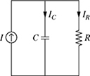
5-10. In the parallel RC circuit shown in Fig. P5.10, the total current I is the sum of the currents flowing through the resistor (IR) and the capacitor (IC). Assume IR = 83.2 ∠−33.7°mA and IC = 55.5 ∠56.3°mA.
(a) Write IR and IL in rectangular form.
(b) Determine I = IR + IL in both its rectangular and polar forms.
(c) Write the real and imaginary parts of I.
-
5-11. Repeat problem P5-10 if IR = 0.5 ∠0°mA and IC = 0.2 ∠90°mA.
-
5-12. Repeat problem P5-10 if IR = 0.929 ∠−21.8°A and IC = 0.37 ∠68.2°A.
-
5-13. The output voltage across the capacitor in a series RLC circuit is measured by an oscilloscope as vo(t) = 15 cos(120 π t − 60°) V. Write the voltage vo(t) in the exponential form.
-
5-14. The current flowing through the resistor in a parallel RL circuit is given as iR(t) = 5 sin(5π t + 30°) mA. Write the current iR(t) in the exponential form.
-
5-15. A resistor, capacitor, and an inductor are connected in series as shown in Fig. P5.15. The total impedance of the circuit is Z = ZR + ZL + ZC, where ZR = R Ω, ZL = j ωL Ω, and
 Ω. For a particular design R = 100 Ω, L = 500 mH, C = 25 μ F, and ω = 120 π rad/s.
(a) Determine the total impedance Z in rectangular form.
(b) Determine the total impedance Z in polar form.
(c) Determine the complex conjugate Z* and compute the product Z Z*.
-
5-16. Two circuit elements are connected in series as shown in Fig. P5.16. The impedance of the first circuit element is Z1 = R1 + j XL1. The impedance of the second circuit element is Z2 = R2 + j XL2, where R1 = 10 Ω, R2 = 5 Ω, XL1 = 25 Ω, and XL2 = 15 Ω.
(a) Determine the total impedance, Z = Z1 + Z2.
(b) Determine the magnitude and phase of the total impedance; in other words find Z = |Z|∠θ.

Figure P5.16 Two circuit elements in series for problem P5-16.
-
5-17. An RC circuit is subjected to an alternating voltage source V as shown in Fig. P5.17. The relationship between the voltage and current is V = I Z, where Z = R − j XC. For a particular design, R = 4 Ω and XC = 2 Ω.
(a) Find I if V = 120 ∠30°V.
(b) Find V if I = 7.0 ∠45°A.

Figure P5.17 RC circuit subjected to an alternating voltage source for problem P5-17.
-
5-18. A series-parallel electric circuit consists of the components shown in Fig. P5.18. The values of the impedance of the two components are
 and Z2 = R + j ωL, where C = 5 μF, R = 100 Ω, L = 0.15 H, ω = 120 π rad/s, and j =
  .
.(a) Write Z1 and Z2 as complex numbers in both their rectangular and polar forms.
(b) Write down the complex conjugate of Z2 and calculate the product
 .
.(c) Calculate the total impedance Z =
 of the circuit. Write the total impedance in both its rectangular and polar forms.
Figure P5.18 Impedance of series-parallel combination of circuit elements for problem P5-18.
-
5-19. The circuit shown in Fig. P5.19 consists of a resistor R, an inductor L, and a capacitor C. The impedance of the resistor is Z1 = R Ω, the impedance of the inductor is Z2 = j ω L Ω, and the impedance of the capacitor is Z3 =
 , where
  . For a particular design, R = 100 Ω, L = 15 mH, C = 25 μF, and ω = 120 π rad/s.
(a) Compute the quantity Z2 + Z3, and express the result in both rectangular and polar forms.
(b) Compute the quantity Z1 + Z2 + Z3, and express the result in both rectangular and polar forms.
(c) Compute the transfer function H =
 and express the result in both rectangular and polar forms.
(d) Determine the complex conjugate of H and compute the product H H*.
Figure P5.19 Transfer function of series-parallel circuit for problem P5-19.
-
5-20. An electric circuit consists of two components as shown in Fig. P5.20. The values of the impedance of the two components are Z1 = R1 + j XL and Z2 = R2 − j XC, where R1 = 75 Ω, XL = 100 Ω, R2 = 50 Ω, and XC = 125 Ω.
(a) Write Z1 and Z2 as complex numbers in both their rectangular and polar forms.
(b) Determine the complex conjugate of Z2 and compute the product
.(c) Compute the total impedance of the two components
 and express the result in both rectangular and polar forms.
Figure P5.20 Impedance of elements connected in parallel for problem P5-20.
-
5-21. A sinusoidal voltage source V = 110 V of frequency 60 Hz (ω = 120 π rad/s) is applied to an RLC circuit as shown in Fig. P5.21, where ZR = R Ω, ZL = j ω L Ω, and
 . Assuming that R = 100 Ω,
  mH, C =
  μF, and j2 = −1,
(a) Write ZR, ZL, and ZC as complex numbers in both their rectangular and polar forms.
(b) If the total impedance is Z = ZR + ZL + ZC, write Z in both rectangular and polar forms.
(c) Determine the complex conjugate of Z and compute the product Z Z*.
(d) If
 , find the voltage in both rectangular and polar forms.
-
5-22. A sinusoidal voltage source V =
 is applied to an circuit shown in Fig. P5.22, where Z1 = R1 − j XC Ω and Z2 = R2 + j XL Ω. The voltage V1 is given by
Assuming that R1 = 50 Ω, R2 = 100 Ω, XL = 250 Ω, and XC = 100 Ω,
(a) Write Z1 and Z2 as complex numbers in polar form.
(b) Determine V1 in both rectangular and polar forms.
(c) Determine the complex conjugate of Z1 and compute the product
 .
.
-
5-23. An electric circuit consists of a resistor R, an inductor L, and a capacitor C, connected as shown in Fig. P5.23. The impedance of the resistor is ZR = R Ω, the impedance of the inductor is ZL = jωL Ω, and the impedance of the capacitor is
 , where j = . Suppose R = 9 Ω, L = 3 mH, C = 250 μF, and ω = 1000 rad/s.
Figure P5.23 Series-parallel combination of R, L, and C for problem P5-23.
(a) Write ZR, ZL, and ZC as complex numbers in both rectangular and polar form.
(b) Calculate the total impedance of the inductor-capacitor parallel combination, which is given as ZLC =
 . Express the result in both rectangular and polar forms.
(c) Now suppose that the total impedance of the circuit is Z = ZR + ZLC. Determine the total impedance in both rectangular and polar forms.
(d) Determine the complex conjugate of Z and compute the product Z Z*.
-
5-24. In the circuit shown in Fig. P5.24, the impedances of the various components are ZR = R Ω, ZL = j XL Ω, and
 , where
  . Suppose R = 120 Ω,
  , and
, and  .
.(a) Express the impedance ZR, ZL, and ZC as complex numbers in both rectangular and polar forms.
(b) Now, suppose that the total impedance of the circuit is Z =
 . Determine the total impedance and express the result in both rectangular and polar forms.
(c) Determine the complex conjugate of Z and compute the product Z Z*.

Figure P5.24 A capacitor connected in series with a parallel combination of resistor and inductor for problem P5-24.
-
5-25. In the RC circuit shown in Fig. P5.25, the impedances of R and C are given as ZR = R Ω and ZC = −jXC Ω, where
 . Suppose R = 100 Ω and XC = 50 Ω.
(a) Express the impedances ZR and ZC as complex numbers in both rectangular and polar forms.
(b) Find the total impedance Z = ZR + ZC as a complex number in both rectangular and polar forms.
(c) If V = 100∠0°V, find the current
 as a complex number in both rectangular and polar forms.
(d) Knowing the current in part (c), find the voltage phasors VR = I ZR and VC = I ZC in both rectangular and polar forms.
(e) Show that the KVL is satisfied for the circuit shown in Fig. P5.25; in other words, show V = VR + VC.

-
5-26. In the RL circuit shown in Fig. P5.26, the impedances of R and L are given as ZR = R Ω and ZC = jXL Ω, where
. Suppose R = 100 Ω and XL = 50 Ω.
Figure P5.26 An RL circuit for problem P5-26.
(a) Express the impedances ZR and ZL as complex numbers in both rectangular and polar forms.
(b) Find the total impedance Z = ZR + ZL as a complex number in both rectangular and polar forms.
(c) If V = 100∠0°V, find the current
 as a complex number in both rectangular and polar forms.
(d) Knowing the current in part (c), find the voltage phasors VR = I ZR and VL = I ZL in both rectangular and polar forms.
(e) Show that the KVL is satisfied for the circuit shown in Fig. P5.26; in other words, show V = VR + VL.
-
5-27. A resistor, capacitor, and inductor are connected in series as shown in Fig. P5.27. The total impedance of the circuit is Z = ZR + ZL + ZC, where ZR = R Ω, ZL = j ωL Ω, and ZC =
 . For a particular design, R = 100 Ω, L = 500 mH, C = 25 μF, and ω = 120 π rad/s.
Figure P5.27 RLC circuit for problem P5-27.
(a) Express the impedances ZR, ZL, and ZC as complex numbers in both rectangular and polar forms.
(b) Determine the total impedance Z in both its rectangular and polar forms.
(c) If V = 100∠0°V, find the current
 as a complex number in both rectangular and polar forms.
(d) Show that the KVL is satisfied for the circuit shown in Fig. P5.27 (i.e., show V = VR + VL + VC).
-
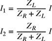
5-28. In the current divider circuit shown in Fig. P5.28, the sum of the current phasors I1 and I2 is equal to the total current phasor I (i.e., I = I1 + I2). Suppose I1 = 1∠0° and I2 = 1∠90°, both measured in mA.

Figure P5.28 A current divider circuit for problems P5-28 and P5-29.
(a) Write I1 and I2 in rectangular form.
(b) Determine the total current phasor I in both rectangular and polar forms.
(c) Suppose ZR = 1000 Ω and ZC =
 . Write VR and VC as complex numbers in both rectangular and polar forms if VR = I1 × ZR and VC = I2 × ZC.
 -
5-29. In the current divider circuit shown in Fig. P5.28, the currents flowing through the resistor I1 and capacitor I2 are given by

where ZR = RΩ is the impedance of the resistor and
 is the impedance of the capacitor.
(a) If R = 1 kΩ and XC = 103 Ω, express ZR and ZC as complex numbers in both rectangular and polar forms.
(b) If I = 1 mA, determine I1 and I2 in both rectangular and polar forms.
(c) Show I = I1 + I2.
-
5-30. In the current divider circuit shown in Fig. P5.30, the sum of the current phasors I1 and I2 is equal to the total current phasor I (i.e., I = I1 + I2).

Figure P5.30 A current divider circuit for problems P5-30 and P5-31.
Suppose
 and
and  ∠−45°, both measured in mA.
(a) Write I1 and I2 in rectangular form.
(b) Determine the total current phasor I in both rectangular and polar forms.
(c) Suppose ZR = 1000Ω and ZL = j 1000Ω. Write VR and VL as complex numbers in both rectangular and polar forms if VR = I1 × ZR and VL = I2 × ZL.
-
5-31. In the current divider circuit shown in Fig. P5.30, the currents flowing through the resistor I1 and inductor I2 are given by
where ZR = RΩ is the impedance of the resistor and ZL = jXLΩ is the impedance of the inductor.
(a) If R = 1kΩ and XL = 103 Ω, express ZR and ZL as complex numbers in both rectangular and polar forms.
(b) If I = 1 mA, determine I1 and I2 in both rectangular and polar forms.
(c) Show I = I1 + I2.
-
5-32. In the Op–Amp circuit shown in Fig. P5.32, the output voltage Vo is given by

where ZR = R Ω is the impedance of the resistor and ZC = −jXC Ω is the impedance of the capacitor.
(a) If R = 2kΩ and XC = 1 kΩ, express ZR and ZC as complex numbers in both rectangular and polar forms.
(b) If Vin = 10∠0°V, determine Vo in both rectangular and polar forms.
-
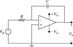
5-33. In the Op–Amp circuit shown in Fig. P5.33, the output voltage Vo is given by

where ZR = R Ω is the impedance of the resistor and ZC = −jXC Ω is the impedance of the capacitor.
(a) If R = 1kΩ and XC = 2 kΩ, express ZR and ZC as complex numbers in both rectangular and polar forms.
(b) If Vin = 5∠90°V, determine Vo in both rectangular and polar forms.

-
5-34. In the Op–Amp circuit shown in Fig. P5.34, the output voltage Vo is given by

where ZR1 = R1 Ω is the impedance of the resistor R1, ZR2 = R2 Ω is the impedance of the resistor R2, and ZC = −jXC Ω is the impedance of the capacitor.
(a) If R1 = 1kΩ, R2 = 2kΩ, and XC = 2 kΩ, express ZR1, ZR2, and ZC as complex numbers in both rectangular and polar forms.
(b) If Vin = 2∠45°V, determine Vo in both rectangular and polar forms.
-
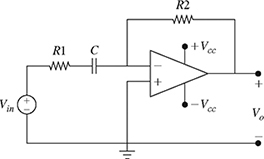
5-35. In the Op–Amp circuit shown in Fig. P5.35, the output voltage Vo is given by

where ZR1 = R1 Ω is the impedance of the resistor R1, ZR2 = R2 Ω is the impedance of the resistor R2, and ZC = −jXC Ω is the impedance of the capacitor.
(a) If R1 = 1.5kΩ, R2 = 1kΩ and XC = 0.5 kΩ, express ZR1, ZR2, and ZC as complex numbers in both rectangular and polar forms.
(b) If Vin = 1∠−45°V, determine Vo in both rectangular and polar forms.
-
5-36. In the Op–Amp circuit circuit shown in Fig. P5.36, the output voltage Vo is given by

where ZR1 = R1 Ω is the impedance of the resistor R1, ZR2 = R2 Ω is the impedance of the resistor R2, ZC1 = −jXC1 Ω is the impedance of the capacitor C1, and ZC2 = −jXC2 Ω is the impedance of the capacitor C2.
(a) If R1 = 10 kΩ, R2 = 5kΩ, XC1 = 2.5 kΩ, and XC2 = 5 kΩ, express ZR1, ZR2, ZC1, and ZC2 as complex numbers in both rectangular and polar forms.
(b) If Vin = 1.5∠0°V, determine Vo in both rectangular and polar forms.

-
5-37. The Delta-to-Yee (Δ-Y) and Yee-to-Delta (Y-Δ) conversions are used in electrical circuits to find the equivalent impedances of complex circuits. In the circuit shown in Fig. 5.37, the impedances Za, Zb, and Zc connected in the Delta interconnection can be converted into their equivalent impedances Z1, Z2, and Z3 connected in the Yee interconnection. The impedances Z1, Z2, and Z3 can be written in term of impedances Za, Zb, and Zc as

(a) If Za = 20 Ω, Zb = −j 10 Ω, and Zc = 20 + j 50 Ω, express Za, Zb, and Zc as complex numbers in both rectangular and polar forms.
(b) Determine Z1, Z2, and Z3 in both rectangular and polar forms.

Figure P5.37 Impedances connected in Delta and Yee interconnections.
-
5-38. Repeat problem P5-37 if Za = 10 Ω, Zb = j 20 Ω, and Zc = 20 + j 10 Ω.
-
5-39. In the circuit shown in Fig. 5.37, the impedances Z1, Z2, and Z3 connected in the Yee interconnection can be converted into their equivalent impedances Za, Zb, and Zc connected in the Delta interconnection as

(a) If Z1 = 2.5 − j 2.5 Ω, Z2 = 17.5 + j 7.5 Ω, and Z3 = 3.75 − j 8.75 Ω, express Z1, Z2, and Z3 as complex numbers in polar form.
(b) Determine Za, Zb, and Zc in both rectangular and polar forms.
-
5-40. Repeat problem P5-39 if Z1 = 3.33 + j 3.33 Ω, Z2 = 5.0 − j 1.66 Ω, and Z3 = 3.5 + j 10.6 Ω.