
Chapter 4
Creating Shapes
• Drawing lines to the screen
• Working with the context menu
• Creating complex shapes
In this chapter you will learn how to draw shapes to the screen. Shapes add interest and dimension to your applications. You will start by learning how to draw a basic line. From there you will move on to a polyline and then to a rectilinear shape. From these basic rectilinear shapes, you will move on to polygons and curvilinear shapes.
NOTE
If you are interested in game development or other animation-based media, polygons are very important. Polygons create the base of most 3-D objects.
Drawing Shapes
You will be drawing shapes on your application, in this chapter, without the help of the Snippets menu. The Snippets are very good tools, and can be extremely handy when you need some quick code. The problem is that if you rely too heavily on this automatically produced code, you will not learn how to create these elements on your own. The goal in learning a new language is to gain the knowledge needed to write code. However, if you only learn to rely on automated Snippets, you really will not learn that much.
In the following six sections, you will begin drawing lines to the screen. As you move through these sections, you will start to create more complicated shapes, including polygons and ellipses. Finally, you will draw pre-rendered images to the screen before moving on to applying effects.
Before You Begin
To begin, you need to prepare your project. All the lessons in this chapter can be done in a single script file. Create a new script file (using the empty JavaFX File template) named Chapter4.fx. Using the lessons covered in Chapter 2, create a Stage and a Scene.
You will always want to set the files for these chapters as the main class for the project. To do this, right-click the Project and go to Properties | Run Properties and set the current file, Chapter4.fx, as the main class.
Before continuing with this chapter, ensure the code in your Chapter4.fx file looks like this:
/*
 * Chapter4.fx
 *
 * v1.0 - J. F. DiMarzio
 *
 * 5/11/2010 - created
 *
 * Creating basic shapes
 *
 */
package com.jfdimarzio.javafxforbeginners;
import javafx.stage.Stage;
import javafx.scene.Scene;

/**
 * @author JFDiMarzio
 */
Stage {
    title : "Basic Shapes"
    onClose: function () {  }
    scene: Scene {
        width: 200
        height: 200
        content: [  ]
    }
}
Lines and Polylines
A line is the most basic form of a shape. Almost any shape you can think of, draw, or create is made up of one or more lines. From squares and triangles, as collections of straight lines, to circles and ellipses, as collections of curved lines, understanding the basics of line drawing is crucial.
Given that almost all other shapes you will draw are based on the line, it seems logical to begin this chapter learning about lines.
What is a line? This may seem like an elementary question. We have all been drawing lines on paper, with pencils, crayons, and markers, since our earliest school days. You can use that experience of drawing lines on paper with a crayon to understand what a “line” is to JavaFX.
When you draw a line on a piece of paper, you place your crayon down on one point, drag it across to another point, and lift up the crayon. The line you draw is as thick as the crayon you used to draw it. The line is also the same color as the crayon. This same logic can be applied to drawing a line in JavaFX.
When you draw a line in JavaFX, you must tell the compiler the start point and end point of your line. The values you need to specify are startX and startY as well as endX and endY. The compiler will be able to take this information and draw a line on the screen between these two points.
NOTE
The start and end points are expressed using the Cartesian coordinate system explained in Chapter 3.
You must start by specifying an import statement in your script. The import statement you need contains the code for drawing lines. The package for lines is required for the compiler to understand what your script is trying to do, and to draw a line accordingly.
At the top of your Chapter4.fx script, under the existing import statements, include the following statement:
import javafx.scene.shape.Line;
You will learn two different shortcuts now for drawing the line. First, place your cursor within the brackets—that is, between [ and ]—that follow the Scene content attribute in your script. Type in the word Line between the brackets, followed by opening and closing curly braces ({}). Place your cursor between the curly braces. Now you are going to bring up the context menu to help you do the rest.
With the cursor still in between the curly braces, press the CRTL-SPACEBAR. This keystroke shortcut will bring up the context menu shown in Figure 4-1.
The context menu is an invaluable tool that shows you all the options available to you from a specific place in your script. The context menu can be used to discover elements or attributes that you otherwise would not be aware of. The context menu can even be used to see some of the values that can be assigned to attributes.
When you call the context menu after an element name, but before the element’s curly braces, the menu will show you the structure of the element. If you call the context menu from within the curly braces of an element, it will show you all the available attributes for that element. You should commit the CRTL-SPACEBAR keystroke shortcut to memory because you will find yourself using it quite often.
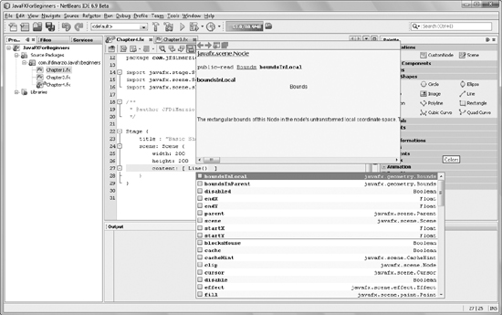
If you press the ENTER key while the context menu is on an attribute, as shown in Figure 4-1, that attributes will be inserted the into your script.
Notice that in your context menu, one of the attributes you can add is startX. The startX attribute is one of the four attributes you need to specify to draw the line. Make sure the startX attribute is highlighted and press the ENTER key.
The context menu should have inserted in startX attribute and a colon (:), as shown in Figure 4-2.
Assign the startX attribute a value of 10. Keep in mind that all the attributes for an element are separated by a comma, semicolon, or nothing. The fact is that JavaFX is very forgiving when it comes to attribute delimiters. With that said, try to stick with using a semicolon, just to be standardized. Therefore, insert a semicolon after the startX value and bring up the context menu again. Use the context menu to insert startY and assign it a value of 10 as well.
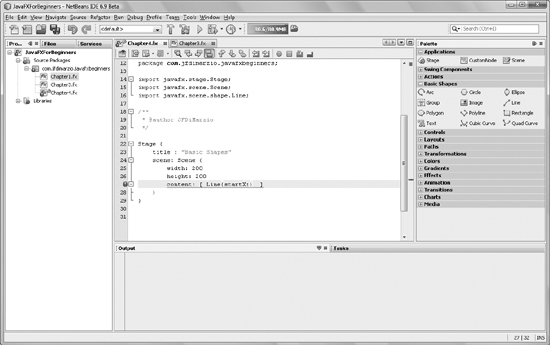
Figure 4-2 Adding an attribute with the context menu
You will be drawing a line that extends from x10, y10 to x150, y150. Seeing as you have just assigned 10,10 to startX and startY, use the context menu to finish assigning the correct values to endX and endY. Your finished script should look like this:
package com.jfdimarzio.javafxforbeginners;
import javafx.stage.Stage;
import javafx.scene.Scene;
import javafx.scene.shape.Line;

/**
 * @author JFDiMarzio
 */
Stage {
    title : "Basic Shapes"
    scene: Scene {
        width: 200
        height: 200
        content: [ Line {startX : 10;
                   startY : 10;
                   endX : 150;
                   endY : 150;
                   }
                 ]
    }
}
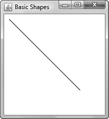
Run your script, and you should get a line that looks like the one shown in Figure 4-3.
This looks like a great line, and you should be very proud of the job you have done—but all things considered, it is not very exciting. You can assign a few more attributes to this line to make it a little more interesting. The discussion that follows details all the attributes available to the Line element.
To begin, to make your line a little thicker, add an attribute to your Line element called strokeWidth. The stroke Width attribute does exactly what the name implies—it governs the thickness or width of the Line element. Assign the stroke Width attribute a value of 15. This will make your line stand out a bit more.
Adding some color to your line will make it pop out even more. Color is a common attribute for shapes. To work with color, you need to import the javafx.scene.paint.Color package. Therefore, add the following import statement to your script:
import javafx.scene.paint.Color;
To color the Line element a nice shade of tomato red, create a stroke attribute and assign it a value of Color.TOMATO. The stroke attribute acts just like the stroke of a paint brush. It can contain information about color, gradients, and other visually appealing details of a shape. Here’s the code for the stroke attribute:
stroke : Color.TOMATO
Your new Line element should have the following attributes and values:
Line {startX : 10;
         startY : 10;
         endX : 150;
         endY : 150;
         strokeWidth: 15;
         stroke: Color.TOMATO
     }
Run your script, and you will see a nice red line from the upper left to the lower right of the screen.
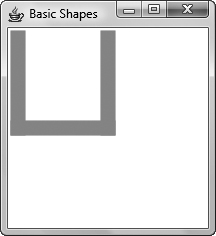
Let’s draw three of these lines to form the shape of the letter U. Try to lay out the three lines on your own. The first line should run down the left side of the screen. The second line should run from end of the first line, across the bottom, to the right side of the screen. Finally, the third line should run from the end of the bottom line to the top on the right side of the screen. When you are finished, compare your code to the code that follows:
package com.jfdimarzio.javafxforbeginners;
import javafx.stage.Stage;
import javafx.scene.Scene;
import javafx.scene.shape.Line;
import javafx.scene.paint.Color;

/**
 * @author JFDiMarzio
 */
Stage {
    title : "Basic Shapes"
    scene: Scene {
        width: 200
        height: 200
        content: [Line {
            startX : 10;
            startY : 10;
            endX : 10;
            endY : 100;
            strokeWidth : 15
            stroke: Color.TOMATO;
        }
        Line {
              startX : 10;
              startY : 100;
              endX : 100;
              endY : 100;
              strokeWidth : 15;
              stroke: Color.TOMATO;
         }
        Line {
              startX : 100;
              startY : 100;
              endX : 100;
              endY : 10;
              strokeWidth : 15
              stroke: Color.TOMATO;
              }
         ]
    }
}
Run your code and compare the results to those in Figure 4-4.
Drawing separate lines for every shape and configuration you can think of is not a very economic use of your time as a developer. Just imagine what it would be like if you had to draw every line, one at a time, to form simple shapes. Luckily there is another type of line called a polyline. It lets you specify more than one point in one line, the last of which is the end point. Specifying more than one end point lets you draw more complex lines with less code. Let’s try to draw the same U-shaped, three-line configuration using a Polyline element.
The first step to using a Polyline element is to import the Polyline package. The code for using polylines is different from the code for lines. For this reason, you need to import a separate package to work with polylines:
import javafx.scene.shape.Polyline;
With the package imported, once again place your cursor in the Scene’s content attribute and type Polyline. Bring up the context menu to view the available attributes.
Notice that there are no definitions for startX and startY. Rather, a Polyline accepts one attribute, called “points.” The points attribute requires an array of values.
NOTE
An array is a collection of values that can be used and referenced as one value. In JavaFX, arrays appear between brackets.
TIP
The content attribute accepts an array of values.
When you’re passing an array of points to a Polyline element, it is understood that the first point will be the start point, and the last will be the end point. The Polyline code will instinctively draw your line between these points, stopping at all other points in your array. You can easily replicate the “U” formation of lines you created with Line using an array of points in Polyline.
An array of points that will match the points used in the Line example should look like this:
[10,10, 10,100, 100,100, 100,10]
Note that each value in the array is separated by a comma.
TIP
To keep the array visually easy to understand, you can separate each x, y pair with a space. Whitespace within an array will be ignored by the compiler and can be added to make your array easy to read.
Run the following code. It should produce the same three-lined U shape as the previous example—with much less code:
package com.jfdimarzio.javafxforbeginners;

import javafx.stage.Stage;
import javafx.scene.Scene;
import javafx.scene.paint.Color;
import javafx.scene.shape.Polyline;

/**
 * @author JFDiMarzio
 */
Stage {
    title : "Basic Shapes"
     scene: Scene {
        width: 200
        height: 200
        content: [Polyline {
                           points : [10,10, 10,100, 100,100, 100,10];
                           strokeWidth : 15;
                           stroke: Color.TOMATO
                            }
                  ]
           }
}
Explore the remaining attributes of the Polyline element. You will find that many of the attributes match that of the line. This makes transitioning script from Line to Polyline quick and easy.
With this section complete, you have learned how to create simple lines and draw them to the screen. In the next section you will start to apply some of the knowledge you have picked up in the previous section and begin to create more complex shapes such as rectilinear and curvilinear objects.
Rectangles
The JavaFX Rectangle element is used to refer to either a square or rectangle. It is used to draw any parallel-lined, four-sided shape. Given that the only difference between rectangles and squares is the length of a set of sides, it only makes sense that the same element can be used to draw either shape.
In the previous section you learned that a Polyline takes an array of points to create a multilined shape. The Rectangle refines this process by only requiring one point be specified. When you create a rectangle, you only need to specify the point for the upperleft corner of the shape. This point, when combined with a defined width and height, will give you a finished shape.
The code that is needed to create rectangles is contained within a separate package from that of the core JavaFX code. You will need to import the javafx.scene.shape.Rectangle package before you can create a rectangle. Therefore, insert the following import statements into your script:
import javafx.scene.shape.Rectangle;
import javafx.scene.paint.Color;
You are going to draw a rectangle that starts at the point x10, y10. It will be 100 pixels wide and 150 pixels high.
NOTE
Do not get confused by the term height. The height of a rectangle is actually calculated from the start point, down (not the start point, up, as the name might imply). Therefore, a rectangle that starts at the point 1,1 and has a height of 100 will extend 100 pixels down from the point 1,1.
You will be specifying seven attributes for the Rectangle element:
• x The x coordinate for the upper-left corner of the rectangle
• y The y coordinate for the upper-left corner of the rectangle
• width The width of the rectangle
• height The height of the rectangle
• fill The color of the interior area of the rectangle
• stroke The attributes of the lines used to draw the rectangle
• strokeWidth The size of the line used to draw the rectangle
The first four attributes, shown next, are self-explanatory and are easy to determine the values of:
Rectangle{
       x: 10;
       y:10;
       width: 100;
       height: 150;
}
The remaining three attributes may require a little explanation. All basic shapes, with the exceptions of lines and polylines, are filled in with Color.BLACK by default. For the purposes of the example you are building here, you only want to have the lines of the rectangle visible. Therefore, to have the rectangle not be filled with color and only expose the lines that create its border, you have to explicitly set the fill attribute to null.
Finally, the stroke and the strokeWidth attributes will be set just as they were in the previous section. That is, set the stroke to Color.BLACK and the strokeWidth to 5. Keep in mind, the stroke and strokeWidth only refer to the lines of the rectangle, not the inner area of the rectangle.
Your finished Rectangle code should look like this:
Stage {

    title : "Basic Shapes"
    scene: Scene {
        width: 200
        height: 200
        content: [Rectangle {
            x : 10;
            y : 10;
            width : 100;
            height : 150;
            fill: null;
            stroke: Color.BLACK;
            strokeWidth : 5
          }
       ]
    }
}
TIP
To see what the rectangle looks like filled in, removed the fill attribute or set it to a specific color.
Notice that the line color is governed by the stoke attribute, whereas the interior color is governed by the fill attribute. This means that you can have a rectangle with a different line color and a different fill color. Here’s an example:
Rectangle {
            x : 10;
            y : 10;
            width : 100;
            height : 150;
            fill: Color.BLUE;
            stroke: Color.RED;
            strokeWidth : 5
        }
There are two more interesting attributes of the Rectangle element that are worth noting. If you want to round out the corners of your rectangle, you can use two attributes—arcWidth and arcHeight—to control the rounding. The attributes arcWidth and arcHeight are used to define that amount of arc that is used when rounding the corners of the rectangle.
The arcWidth and arcHeight attributes are not available to Line or Polyline because this would basically turn the lines and polylines into arcs. Arcs are covered a bit later in this chapter.
Try the following code to round the corners of your rectangle:
Stage {
     title : "Basic Shapes"
     scene: Scene {
         width: 200
         height: 200
         content: [Rectangle {
             x : 10;
             y : 10;
             width : 100;
             height : 150;
             fill: null;
             stroke: Color.BLACK;
             strokeWidth : 5;
             arcWidth : 20;
             arcHeight : 20
        } ]
    }
}
Now that you have learned how to draw a rectangle on the screen, you can move on to a more complex shape—a polygon. The next section will discuss the process for drawing Polygons, or multisided shapes, to the screen using JavaFX script.
Polygons
A polygon is to a rectangle what the polyline is to the line. Polygon elements are set up similarly to Polyline (discussed in a previous section of this chapter). Whereas Line and Rectangle accept a fixed number of coordinates to use a point, Polyline and Polygon accept an array of points.
Polygons will draw lines between all the points you specify in your points array, the same way Polyline does.
NOTE
The same rules about color that apply to Rectangle elements also apply to Polygon elements. By default, all polygons are filled with black. Also, the line color and fill color are governed by the stroke and fill attributes, respectively.
The following sample code draws a simple, small octagon on the screen using the Polygon element:
package com.jfdimarzio.javafxforbeginners;
import javafx.stage.Stage;
import javafx.scene.Scene;
import javafx.scene.shape.Polygon;

/**
 * @author jdimarz
 */

Stage {
    title : "Basic Shapes"
    scene: Scene {
        width: 400
        height: 400
        content: [Polygon {
            points: [
                  90,80,
                  190,80,
                  240,130,
                  240,220,
                  190,270,
                  90,270,
                  40,220,
                  40,130 ]
        }]
    }
}
Notice that you do not need to specify the final point of the polygon as being the same as the first point. JavaFX will automatically know that it should connect the last point in your array with the first point to complete the shape.
In the next section of this chapter you will learn how to create curvilinear shapes such as arcs, circles, and ellipses.
Arcs
While on the surface an arc may seem like a simple shape, it can be very complicated for a computer to understand. People look at an arc and think, “It’s just a piece of a circle.” To a computer an arc is composed of complex radius and center points, angles, and circumference lengths.
An Arc element takes seven basic attributes. Given the complexity of drawing an arc as opposed to drawing a straight line, the attributes needed to complete an arc are unlike those you have seen so far in this chapter and therefore need some explanation. To begin, import the following packages:
import javafx.scene.shape.Arc;
import javafx.scene.shape.ArcType;
The first two required attributes are centerX and centerY:
centerX: 125;
centerY: 125;
Think of a circle for a moment. An arc would be a segment of that circle. JavaFX thinks of an arc as a circle that it only has to draw part of. Therefore, the centerX and centerY attributes represent the center point of the circle that the arc would form if it was completed.
The next two attributes are radiusX and radiusY:
radiusX: 50;
radiusY: 50;
Every circle extends a certain distance from its center. This distance is the radius. The Arc element requires that you specify a radius. However, the naming of the attributes may be a little misleading. RadiusX and radiusY do not represent a point. Rather, they represent the radius in length along the x and y axes. Having two separate radial lengths lets you create oblong arcs.
TIP
To make a circular arc, set the radiusX and radiusY attributes to the same value.
The next required attribute is startAngle:
startAngle: 45;
The startAngle represents an invisible line that extends from your center point to the actual start point of your arc. This line is at a given angle. Therefore, a startAngle of 45 mean that the arc will begin at a 45-degree angle to the center point.
The next attribute that is required to create an arc is the length:
length: 270;
The other length-related attributes you have worked with thus far, such as width and height, have been based on pixel length. The Arc attribute of length is a representation of the number of degrees that the arc travels from its start point. Therefore, if you have a length with a value of 270, your arc will extend 270 degrees from the start point, around the center point.
The next Arc attribute is type:
type: ArcType.OPEN;
The type attribute of the Arc element describes how the arc is draw. Three different ArcType values can be assigned to this attribute:
• ArcType.OPEN Draws the arc as an open-ended curved line
• ArcType.ROUND Draws the arc while connecting the two end points back to the center point, much like a pie with a piece missing
• ArcType.CHORD Draws the arc and then connects the two end points to each other with a straight line
The last attribute you need to set is the fill attribute. The fill attribute is the same for an Arc element as it is for other shape elements. For the purposes of this example, set the fill attribute to null.
Optionally, you can set the stroke and strokeWidth attributes as you have done in the past sections. Run the code that follows to create an arc that looks like a pie with a missing piece:
NOTE
You will need to import the javafx.scene.paint.Color package to fill your shape.
Stage {
     title : "Basic Shapes"
     scene: Scene {
         width: 200
         height: 200
         content: [Arc {
             centerX: 125;
             centerY: 125;
             radiusX: 50;
             radiusY: 50;
             startAngle: 45; length: 270;
             type: ArcType.ROUND;
             fill: null;
             stroke: Color.BLACK;
             strokeWidth: 5
            }
        ]
    }
}
Creating arcs, although it requires the use of several attributes that may seem foreign to you, becomes easier as you understand the purpose of each attribute.
In the next section you will create circles and ellipses.
Circles and Ellipses
Creating a circle using JavaFX will seem much easier after you have created an arc. Whereas an Arc element needed seven attributes to govern angles, lengths, and other features, a Circle element only requires three. But before you can create a circle, you must import the appropriate package:
import javafx.scene.shape.Circle;
import javafx.scene.paint.Color;
The three attributes required to create a circle are centerX, centerY, and radius. These attributes function exactly like they do for an arc.
NOTE
The reason a Circle element only has a single value for the radius and not a height and width pair for the radius, like Arc, is because a circle cannot be “oblong.” Therefore, it will always have the same radial value along all axes.
Having a simple set of attributes makes circles easy to create and use in your applications. The following code creates a black outline of a circle:
Stage {
     title : "Basic Shapes"
     scene: Scene {
         width: 200
         height: 200
         content: [Circle {
                     centerX: 100;
                     centerY: 100;
                     radius: 50;
                     fill: null;
                     stroke: Color.BLACK;
                     strokeWidth: 5
                  }
               ]
    }
}
You can use this same process to create an ellipse. The only difference between an ellipse and a circle is that because an ellipse is oblong, the Ellipse element takes an x, y radial pair rather than a set radial length. Here’s the code:
/*
 * Chapter4.fx
 *
 * v1.0 - J. F. DiMarzio
 *
 * 5/11/2010 - created
 *
 * Creating basic shapes
 *
 */

package com.jfdimarzio.javafxforbeginners;

import javafx.stage.Stage;
import javafx.scene.Scene;
import javafx.scene.shape.Ellipse;
import javafx.scene.paint.Color;

Stage {
    title : "Basic Shapes"
    scene: Scene {
        width: 200
        height: 200
        content: [Ellipse {
            centerX: 50,
            centerY: 50,
            radiusX: 35,
            radiusY: 20,
            fill: null;
            stroke: Color.BLACK;
            strokeWidth: 5
         }
         ]
    }
}
Try This Create Multiple Shapes
Take some time out before the next chapter to exercise your new shape-building skills. Although it may seem like a fairly elementary task, you will have a great need to create simple shapes throughout your development career. From designing new buttons, to creating masks, you will always need to create simple shapes.
Try adding multiple shapes to the same Scene. Play with the dimensions and positions of the shapes to keep them from overlapping. Continue to work with them to manipulate how the shapes can touch or cover each other.
This exercise will be useful in future development by giving you a full grasp of how elements are placed in a Scene.
In this chapter, you learned how to create some basic shapes without using the Snippets menu. You created lines, polylines, rectangles, arcs, circles, and ellipses. You also learn about an invaluable tool: the context menu. These skills will help you tremendously throughout the remainder of this book.
In the next chapter, you will learn how to work with and create more colors than what was touched on in this chapter. You will also learn how to apply effects such as opacity and rotation.
 Chapter 4 Self Test
1. What four attributes are needed to draw a line?
2. How do you access the context menu?
3. What three delimiters can follow an attribute definition?
4. What attribute controls the thickness of the line used to draw a shape?
5. What package is needed to draw a polyline?
6. What type of value is assigned to the points attribute of a Polyline element?
7. True or false? The height attribute of the Rectangle element is the number of pixels from the start point to the top of the rectangle.
8. What is the default value for the fill attribute of a Rectangle element?
9. True or false? RadiusX and radiusY comprise the point where the radius extends to.
10. What attribute configures the radius of a circle?