Chapter 6
Film-Free LIFT (FF-LIFT)
Salvatore Surdo, Alberto Diaspro and Martí Duocastella
Department of Nanophysics, Istituto Italiano di Tecnologia, Via Morego 30, 16163 Genova, Italy
6.1 Introduction
The control of inorganic matter into an ever-decreasing size has enabled the technological revolution of the past decades, with developments ranging from computers to medical tools. Arguably, behind these advances lies photolithography, the de facto standard micro/nanofabrication technique [1]. Despite unrivaled results in terms of parallelization, resolution, and feature size, photolithography is highly optimized for a short parameter space, namely few materials (metals or semiconductors) and even fewer substrates (flat silicon or glass). All these intrinsic constraints of photolithography are incompatible with novel key applications such as lab-on-a-chip [2], tissue engineering [3], gene sequencing [4], or organic electronics [5], which demand for the heterogeneous integration of a wide variety of functional materials, including polymers, proteins, or living organisms, at the micro- and nanoscale. Compatibility with flexible substrates or uneven or rough surfaces is also required. Therefore, the big challenge ahead of us is the development of fabrication tools that enable to translate the same degree of control achievable with photolithography into organic or biological matter.
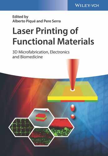
With the previous points in mind, the ideal fabrication technique of the twenty-first century should combine characteristics such as high speed and high lateral resolution, with a total compatibility with a wide range of complex materials. Unfortunately, current techniques capable of patterning functional materials, including inkjet printing [6], dip-pen lithography [7], or soft lithography [8, 9], can only accommodate some of these demands. Within this context, laser-induced forward transfer (LIFT) appears as a much versatile approach for micro- and nanofabrication [10, 11]. LIFT is a printing technique that uses laser pulses to transfer material from a donor film onto a receiver substrate placed in close proximity to the donor film (Figure 6.1a and Chapter 1). An air gap between the donor film and the substrate prevents potential contamination of the transferred material. Notably, since LIFT does not require the use of nozzles, it can print a wider variety of materials compared to inkjet printing, ranging from highly viscous inks [12, 13] to even materials in solid form [14–16]. Despite resolutions typically limited to about 1 µm, the possibility to monitor in situ the printing process coupled with the high directionality of lasers opens the door to unique features. For instance, one could pick up a specific cell or biomolecule from the donor film and deposit it on a targeted area of a substrate. Importantly, LIFT is implemented in a laser direct-write system. Thus, the same setup used for LIFT can be used to ablate or modify a material, complementing the additive nature of LIFT with other laser processing modalities such as laser ablation [17, 18], photostimulation [19], or even optical transfection [20].
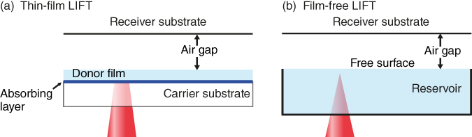
Figure 6.1 Scheme of traditional LIFT of liquids (a) and film-free LIFT (b).
A natural consequence of the versatility of LIFT is the requirement to optimize the printing process depending on the targeted material. In other words, the conditions needed to print a metal completely differ from those used for printing a prepolymer in terms of parameters such as laser wavelength, pulse duration, fluence, or separation distance between the donor film and the receiver substrate. A particularly delicate situation of significant importance arises when the printing material (ink) is a liquid transparent to commercially available laser wavelengths. This is the case of most biological materials, which are usually prepared in aqueous solutions. Therefore, optimizing the laser printing of transparent liquids is necessary for the use of this technique in bioapplications ranging from DNA or protein microarrays [21, 22] to the growing field of biosensors [23, 24]. There are two aspects, though, that have typically limited the use of LIFT in this instance. The first one is the need to promote laser absorption. This is usually done by intercalating an absorbing layer or dynamic release layer (DRL) between the donor film and the carrier substrate [25–32]. Thus, the laser radiation is absorbed in the DRL upon which it volatilizes, generating the thrust necessary to propel the targeted material into the receiver substrate. The DRL has the additional advantage of preventing the direct exposure of the material of interest to the laser irradiation. However, the quest of an ideal DRL has been proved challenging. Traces of most materials used as DRL, including titanium or chromium, are found in the deposited material. Alternative approaches such as the use of explosive polymers that fully decompose with the laser irradiation [33, 34] (Chapter 3), or the use of thick polymers that mechanically deform [35–37] (Chapter 5), can mitigate the contamination caused by the DRL. But even if contamination caused by the DRL could be fully eliminated, there would still be a second problem in the laser printing of transparent liquids: the preparation of a liquid film over large areas. Importantly, the uniformity of the liquid film is directly correlated to the quality of the printing process, for example, different film thicknesses can result in different amounts of deposited material under the same laser conditions. Because of the difficulty in the preparation of liquid films and their inherent instability, a technique that could operate under the same principles of traditional LIFT but without the need to prepare the liquid in thin form would be highly advantageous. This prompted the development of film-free laser printing or film-free LIFT (FF-LIFT), a technique that can directly transfer transparent liquids contained in a reservoir (Figure 6.1b)[38, 39].
In this chapter, we discuss in detail the current problems related to the preparation of liquid films in LIFT, from fundamental aspects to practical problems. We then introduce FF-LIFT, explain its physical principles, and describe the different modalities in which the technique can be implemented. We discuss important experimental factors that can affect the quality of the printing process, such as spherical aberration or optical absorption of the liquid, and finally, we give examples of applications in which FF-LIFT has been successfully used.
6.2 Rheological Considerations in Traditional LIFT of Liquids
The uniformity of the donor film has a direct influence on the outcome of the LIFT printing process. Indeed, parameters such as feature size, energy threshold for printing, printing area, and reproducibility are strongly affected by the local thickness of the liquid film. In this section, we discuss which are the main factors that impact the uniformity of thin liquid films and describe the existing technologies available for liquid film preparation. We also highlight the key aspects to be considered when selecting a receiver substrate.
6.2.1 The Challenges behind the Preparation of a Thin Liquid Film
Ideally, in traditional LIFT of liquids, one would like to have thin films with high temporal stability and spatial uniformity over large areas (∼mm2). Despite the preparation of a liquid film being simple and straightforward, this task can be highly challenging. In fact, thin liquid films are often subjected to several instabilities that compromise their spatiotemporal uniformity [40]. Depending on the mechanism that triggers these instabilities, two main groups can be recognized. The first one involves spontaneous instabilities, namely the intrinsic tendency of a thin liquid film to break into smaller droplets (Figure 6.2a). Typical examples are the Rayleigh–Taylor instability, caused by gravity forces that destabilize a suspended (facing down) film, and liquid dewetting, in which the liquid film is ruptured due to its tendency to withdraw from a “hostile” surface [41, 42]. The second group of instabilities encompasses those induced by external agents (Figure 6.2b) [43], as in the case of capillary waves, that is, pressure waves traveling along the phase boundary of the liquid. Eventually, when the external perturbation ceases, these nonuniformities may vanish due to viscous dissipation. For a given magnitude or frequency of the perturbation, though, the instabilities could also result in permanent film breakup.
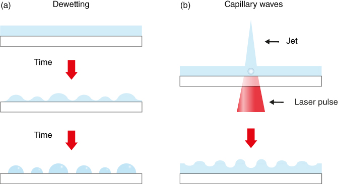
Figure 6.2 Sketch of spontaneous (a) and externally induced (b) instabilities that can affect the spatiotemporal uniformity of a thin liquid donor film.
The occurrence of liquid film instabilities strongly depends on several rheological parameters of the printed material or ink, namely surface tension (γ), mass density (ρ), vapor pressure, and viscosity (υ), as well as on the morphology (e.g., surface roughness) and chemistry (e.g., level of hydrophobicity) of the carrier substrate. Because there exists an interplay between all these parameters, understanding how they affect the donor preparation is not an easy task. To simplify the study, it is useful to distinguish two main stages in which liquid nonuniformities can appear during LIFT. The first one includes the initial preparation of the liquid film, and it is dominated by spontaneous instabilities. The second stage occurs once a uniform film is obtained and involves the formation of capillary waves induced by the laser pulses that act as the external perturbing agent. A more detailed description of each of these stages is presented next.
6.2.1.1 The Role of Spontaneous Instabilities
To understand the challenges behind the initial preparation of a thin liquid film, it is necessary to first clarify the meaning of the term thin. In the context of printing liquids with LIFT, we consider “thin” those films with a thickness in the interval of 5–50 µm. Within this length scale, gravity and consequently the Rayleigh–Taylor instability are negligible. Thus, liquid dewetting is the only potential source of spontaneous liquid instabilities. Importantly, liquid dewetting occurs for films below a critical thickness eC given by the equation
where k−1 = (γ/ρg)1/2 is the capillary length, and γ, ρ, g, and ![]() are the ink surface tension, density, gravitational constant, and equilibrium contact angle, respectively [44]. From Eq. (6.1), it is possible to unveil the main parameters that affect film stability, which as stated earlier, are not limited to the ink rheology, but also include the chemical and morphological properties of the carrier substrate.
are the ink surface tension, density, gravitational constant, and equilibrium contact angle, respectively [44]. From Eq. (6.1), it is possible to unveil the main parameters that affect film stability, which as stated earlier, are not limited to the ink rheology, but also include the chemical and morphological properties of the carrier substrate.
For the sake of simplicity, we limit the discussion on donor film dewetting to two inks, water (![]() = 73 mN/m,
= 73 mN/m, ![]() = 1 × 10³ kg/m3, and
= 1 × 10³ kg/m3, and ![]() = 1 mPa s) and glycerol (γglyc = 63 mN/m, ρglyc = 1.3 × 10³ kg/m3, and υglyc = 1.5 Pa s). Note that these two inks are widely used as model systems in LIFT [45, 46]. Table 6.1 presents a list of the critical thickness eC for various materials used in LIFT. As expected, only when the wettability between the liquid and the carrier substrate is high, it is possible to obtain stable films with a thickness suitable for LIFT.
= 1 mPa s) and glycerol (γglyc = 63 mN/m, ρglyc = 1.3 × 10³ kg/m3, and υglyc = 1.5 Pa s). Note that these two inks are widely used as model systems in LIFT [45, 46]. Table 6.1 presents a list of the critical thickness eC for various materials used in LIFT. As expected, only when the wettability between the liquid and the carrier substrate is high, it is possible to obtain stable films with a thickness suitable for LIFT.
Table 6.1 Contact angle θE of water on metals, oxides, and polymers and the corresponding critical thickness eC below which dewetting occurs
| Material | eC | |
| Metal | ∼0 | ∼100 nm |
| Oxide (e.g., glass) | ∼10–30 | ∼1–10 µm |
| Polymer | ∼60–110 | ∼50–500 µm |
Even if the critical thickness of the two model inks can be, in many cases of practical interest (e.g., metal absorbing layers), well below the typical thickness used in LIFT, the risk of dewetting cannot be completely averted. First of all, any imperfections of the absorbing layer can induce local instabilities that trigger the rupture of the film. To avoid this problem, it is imperative to have clean and uniform carrier substrates. Moreover, several metals oxidize upon exposure to air resulting in a thin oxide film that reduces ink wettability. Thus, inert noble metals such as Au are, a priori, more suitable for LIFT. Finally, because liquid evaporation decreases the film thickness d0, at least locally, the film stability is limited overtime, until d0 < eC. Therefore, the kinetics of film evaporation determines the temporal window during which the donor film remains stable and suitable for printing.
The liquid film evaporation rate (![]() ) can be estimated for a model case, namely the liquid evaporation at the free vapor–liquid interface. This phenomenon is governed by the general form of Dalton's law that can be written as
) can be estimated for a model case, namely the liquid evaporation at the free vapor–liquid interface. This phenomenon is governed by the general form of Dalton's law that can be written as

where hM is the mass transfer coefficient, S the surface area of the film, ![]() the relative humidity,
the relative humidity, ![]() with R0 the gas constant,
with R0 the gas constant, ![]() the vapor molar mass, T the temperature, Pb the vapor pressure, and Psat the saturated vapor pressure. Importantly, hM is a function of additional parameters among which the vapor diffusivity D and the velocity U of the surrounding air (convection) are the most relevant. Remarkably, Eq. (6.2) introduces an additional ink parameter, that is, the ink vapor pressure, which further limits the range of the ink candidates for LIFT. Indeed, the ideal ink should have a low evaporation rate. Note that many organic solvents, which typically feature excellent wettability over a wide variety of substrates, can be discarded as ink candidates because of their typically high vapor pressure. For a water film under standard laboratory conditions,
the vapor molar mass, T the temperature, Pb the vapor pressure, and Psat the saturated vapor pressure. Importantly, hM is a function of additional parameters among which the vapor diffusivity D and the velocity U of the surrounding air (convection) are the most relevant. Remarkably, Eq. (6.2) introduces an additional ink parameter, that is, the ink vapor pressure, which further limits the range of the ink candidates for LIFT. Indeed, the ideal ink should have a low evaporation rate. Note that many organic solvents, which typically feature excellent wettability over a wide variety of substrates, can be discarded as ink candidates because of their typically high vapor pressure. For a water film under standard laboratory conditions, ![]() = 60%, T = 293 K, and U from 0.01 to 1 mm/s, the evaporation rate ranges from approximately 70 to 700 pg/m2 s, which corresponds to a thickness reduction rate ranging from approximately 0.07 to 0.7 µm/s. Thus, a water film with a thickness of about 10 µm prepared on glass becomes unstable (
= 60%, T = 293 K, and U from 0.01 to 1 mm/s, the evaporation rate ranges from approximately 70 to 700 pg/m2 s, which corresponds to a thickness reduction rate ranging from approximately 0.07 to 0.7 µm/s. Thus, a water film with a thickness of about 10 µm prepared on glass becomes unstable (![]() ) within a timescale ranging from tens of seconds to few minutes. This is impracticable for many applications and could limit future industrial implementations of LIFT. In contrast, a glycerol film exhibits good stability over time (evaporation rate
) within a timescale ranging from tens of seconds to few minutes. This is impracticable for many applications and could limit future industrial implementations of LIFT. In contrast, a glycerol film exhibits good stability over time (evaporation rate ![]() nm/s) thanks to its low vapor pressure (∼10 mPa) and high viscosity (1.5 Pa s). As detailed in the next sections, viscosity can be a drawback during the interaction of the liquid film with the laser irradiation. Highly viscous materials are also difficult to spread, and hence, in practice, it is difficult to prepare them in thin form. This is why glycerol is mainly used as an additive for decreasing the vapor pressure of aqueous solutions.
nm/s) thanks to its low vapor pressure (∼10 mPa) and high viscosity (1.5 Pa s). As detailed in the next sections, viscosity can be a drawback during the interaction of the liquid film with the laser irradiation. Highly viscous materials are also difficult to spread, and hence, in practice, it is difficult to prepare them in thin form. This is why glycerol is mainly used as an additive for decreasing the vapor pressure of aqueous solutions.
6.2.1.2 The Role of External Instabilities
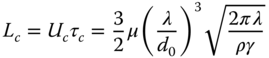
Once a stable donor film is obtained, external agents can degrade the spatiotemporal stability of the liquid. In the case of LIFT, the irradiation of the film with laser pulses is the main external factor that can lead to liquid instabilities. Indeed, as a possible consequence of the liquid–matter interaction, capillary waves are usually generated [47]. The dynamics of these waves can degrade the performance of LIFT. For instance, when two laser pulses are fired in close temporal and spatial proximity, the presence of capillary waves induced by the first pulse can affect the printing process initiated by the second pulse [47, 48] (see Chapter 5 for details). To overcome this issue, the second pulse should be fired temporally or spatially separated from the first pulse. A quantification of the minimal separation (in time or space) between consecutive pulses for which interference by capillary waves is avoided can be estimated by using the lubrication approximation. In this case, capillary waves within a thin liquid layer decay exponentially with a relaxation time ![]() given by the equation
given by the equation

where ![]() is the absolute or dynamic viscosity of the ink, d0 the film thickness, and λ the wavelength of the external disturbance with
is the absolute or dynamic viscosity of the ink, d0 the film thickness, and λ the wavelength of the external disturbance with ![]() [44]. Thus, two pulses that are temporally separated by less than
[44]. Thus, two pulses that are temporally separated by less than ![]() will interfere. This temporal separation can be easily transformed into a spatial distance by considering the propagation velocity of capillary waves
will interfere. This temporal separation can be easily transformed into a spatial distance by considering the propagation velocity of capillary waves ![]() , which is given by
, which is given by

Thus, the minimal spatial distance between two consecutive pulses (![]() ), by combining Eq. (6.3) with Eq. (6.4), is
), by combining Eq. (6.3) with Eq. (6.4), is
Under typical operational conditions, for example, d0 = 10 µm and λ = 40 µm [47], ![]() for a water–glycerol mixture ranges from 35 µs for pure water to 40 ms for pure glycerol, whereas the corresponding
for a water–glycerol mixture ranges from 35 µs for pure water to 40 ms for pure glycerol, whereas the corresponding ![]() would be 180 µm and 180 mm, respectively. A simple estimate of the maximum repetition rate of the printing process (
would be 180 µm and 180 mm, respectively. A simple estimate of the maximum repetition rate of the printing process (![]() ) when the spatial separation between events is below
) when the spatial separation between events is below ![]() , as it occurs in most practical instances, would scale with
, as it occurs in most practical instances, would scale with ![]() , which leads to 28 kHz for water and 25 Hz for glycerol. However, in this assumption, the temporal dynamics of the printing process have not been considered. Thus, the time required for liquid ejection, denoted as
, which leads to 28 kHz for water and 25 Hz for glycerol. However, in this assumption, the temporal dynamics of the printing process have not been considered. Thus, the time required for liquid ejection, denoted as ![]() , further limits
, further limits ![]() . In other words,
. In other words, ![]() , where
, where ![]() also depends on viscosity. These results further highlight the crucial role of the ink rheology on the performance of LIFT, which does not only affect the preparation of the liquid film but can also later alter the throughput of the technique.
also depends on viscosity. These results further highlight the crucial role of the ink rheology on the performance of LIFT, which does not only affect the preparation of the liquid film but can also later alter the throughput of the technique.
Importantly, in the case of FF-LIFT, the values of ![]() and
and ![]() can be greatly reduced. In fact, the damping effects in a bulk liquid help mitigating capillary wave effects [44]. Thus, the use of a film-free approach is less demanding in terms of the rheology of the inks to be printed.
can be greatly reduced. In fact, the damping effects in a bulk liquid help mitigating capillary wave effects [44]. Thus, the use of a film-free approach is less demanding in terms of the rheology of the inks to be printed.
6.2.2 Technologies for Thin-Film Preparation
Even if an ink with the ideal conditions required for LIFT printing was found, one should still look for the optimal existing technology that enables the spreading of the ink into a thin film. Several techniques are now available that enable controlled preparation of thin films at the 5–50 µm range required in LIFT. A brief description of the main features and properties of some of the most used techniques in LIFT is provided next.
- Spin coating. In this approach, a small amount of ink is deposited on the center of a flat substrate, which is then rotated at high speed to uniformly spread the ink over the substrate surface (Figure 6.3a) [49, 50]. During the rotation step, solvents that are present in the ink totally or partially evaporate, leading to a film whose thickness depends on both the rotation speed (ω) and the ink viscosity (υ). In particular, the film thickness decreases with ω, whereas, it increases with υ. Therefore, the use of spin coating further limits the range of available inks for LIFT. This is particularly crucial for polymer inks, since they usually feature high viscosity that limits the minimum thickness of feasible films. Furthermore, this method is not appropriate for water-based inks since a fine control of the water evaporation rate is difficult.
- Dip coating. This technique is based on a two-step process (Figure 6.3b). First, the carrier substrate over which the liquid has to be prepared is immersed in the ink. Second, the substrate is withdrawn at constant speed [50]. During this second step, a thin layer of ink deposits on the substrate, and the retracting speed determines the final thickness. In general (for Newtonian fluids, as the model solutions considered earlier), the faster the withdrawal process, the thicker the resulting film. Compared to spin coating, this method is compatible with water-based films and features a simpler implementation. For highly viscous inks, though, the uniformity of the film can be compromised.
- Blade coating. This method is probably the most used in LIFT thanks to its ease of implementation and limited cost [27, 45]. Initially, a tiny amount of ink is placed in an outer marginal region of a flat substrate. After that, a blade is used to coat the entire substrate with the ink (Figure 6.3c). Because the gap between the blade and the substrate sets the final thickness of the coating, uniform films are feasible regardless of the ink viscosity. Despite its simplicity, any variations of the coating speed compromise the film uniformity.

Figure 6.3 Schematic representation of the main existing technologies for the preparation of thin liquid films: (a) spin coating, (b) dip coating, and (c) blade coating.
6.2.3 Wetting of the Receiver Substrate
There is an additional key factor to be considered in LIFT, and that ultimately dictates the outcome of this printing process: the properties of the receiver substrate. Indeed, the amount of ink deposited on the receiver substrate does not exclusively depend on the rheological properties of the ink or the laser parameters, but it can also be affected by the wetting of the receiver substrate. In LIFT, the printing process is mediated by the formation of a jet that impacts upon the receiver substrate (Chapter 4). Thus, the jet–receiver interaction (wettability, adhesion forces) determines aspects as relevant as the laser fluence threshold required for printing [51] or the final amount of deposited material [52]. As a result, an ink that presents rheological properties optimal for the preparation of the donor film may not necessarily result in good printing. For instance, the addition of surfactants in the liquid to be printed can facilitate liquid wettability on the carrier substrate and thus enables the preparation of stable liquid films. However, the decrease of the surface tension of the ink can also promote wetting on the receiver substrate, resulting in printed droplets with a diameter or volume larger than the ones obtained without the use of surfactant, which is detrimental in terms of printing resolution. This limitation is the consequence of the intrinsic dependence of the LIFT performance on the entire carrier/donor/receiver system. In other words, in traditional LIFT, there is a fundamental coupling between the receiver substrate and the carrier/donor system in terms of the ink properties. Thus, the choice of the ink will always be a trade-off between the optimal ink for the receiver substrate and the ideal rheological properties of the ink for its preparation in film form. In this scenario, the reader can catch a glimpse of the great potential of FF-LIFT, where the ink simply stays in a reservoir, and its rheology can be optimized only with respect to the receiver substrate. Therefore, the film-free approach provides LIFT with the ability to tune the ink with respect to a targeted application rather than to optimize the ink for its suitability as a donor film.
6.3 Fundamentals of Film-Free LIFT
The intrinsic instability of a liquid film and the technical problems associated with the preparation of materials in film form led to the development of a novel laser printing technique capable of depositing a liquid directly from a reservoir. The technique, called film-free LIFT or FF-LIFT, is based on a very simple premise: focus a laser beam underneath the free surface of a liquid contained in a reservoir in order to provide the thrust for liquid ejection. A receiver substrate, placed in close proximity to the free surface, is then used to collect the fraction of liquid ejected. Naturally, the laser beam must be absorbed in a localized area beneath the liquid-free surface for FF-LIFT to properly work. This imposes certain requirements on the optical properties of the liquid of interest or on the laser used, as it is discussed in Section 6.4. But assuming that one can deliver an amount of controlled laser energy within a small volume of a fluid, what is the mechanism that can lead to liquid ejection? What are the fundamental parameters that drive liquid motion? An answer to these questions, with particular emphasis in the differences between FF-LIFT and traditional LIFT, is presented next.
6.3.1 Cavitation-Induced Phenomena for Printing
First, we need to consider how to promote significant liquid ejection or large liquid transport using a laser. This essential step for printing is challenging to implement in practice, and it usually imposes strong requirements on the laser system or liquids to be printed. For instance, in highly light-absorbent liquids, laser-induced temperature gradients can drive large-scale fluid flows [53]. This mechanism, though, is incompatible with biological solutions, which are typically transparent to the laser radiation. In contrast, liquid actuation by cavitation bubbles fulfills the requirements desired in a laser printing technique, namely the possibility to operate with a large amount of liquids (provided they are transparent to the laser radiation) and control of the printed material by means of the laser parameters. Indeed, laser-induced cavitation constitutes the fundamental mechanism of FF-LIFT.
The typical sequence of events in the formation of laser cavitation bubbles starts when a laser pulse is focused within a liquid. Provided the laser intensity is high enough (see Section 6.4), optical breakdown in the liquid can be induced [54, 55]. In analogy to the well-known electrical breakdown of a dielectric under strong electric fields, the molecules of a fluid can be ionized in the presence of laser radiation. As a consequence, a confined and hot plasma can be formed that explosively expands at a velocity faster than the speed of sound in the liquid (i.e., shock wave), resulting in the generation of a cavitation bubble [56, 57]. More importantly, the evolution of this bubble, including its initial growth and final collapse, can induce powerful fluid flows. Depending on the particular conditions of cavitation bubble formation, different scenarios can develop. In particular, when the bubble is generated close to a free surface, a jet perpendicular to the surface is formed, which transports a fraction of liquid away from the surface [58]. The formation of these cavitation jets dictates the outcome of the printing process in FF-LIFT. Thus, it is paramount to understand the interplay between cavitation bubble and jet formation in this printing technique.
6.3.2 Jet Formation in Film-Free LIFT
The initial dynamics of jet formation in FF-LIFT is dependent on only one parameter, the so-called standoff distance ![]() , defined as [59]:
, defined as [59]:

where Rmax is the maximum bubble radius (depends on the laser pulse energy absorbed), and h is the distance from the free surface to the initial bubble centroid. In general, if ![]() > 0.8, the cavitation bubble is far from the free surface for its given Rmax, and only a small protrusion in the surface is formed, which impedes proper printing. In addition, if
> 0.8, the cavitation bubble is far from the free surface for its given Rmax, and only a small protrusion in the surface is formed, which impedes proper printing. In addition, if ![]() < 0.3, bubble bursting can occur prior to jet formation, resulting in splashing in the receiver substrate. Thus, the suitable range for printing in FF-LIFT is usually 0.3 <
< 0.3, bubble bursting can occur prior to jet formation, resulting in splashing in the receiver substrate. Thus, the suitable range for printing in FF-LIFT is usually 0.3 < ![]() < 0.8 [60, 61]. Note that surface tension does not affect the initial formation of a jet, since bubble growth and collapse are inertia-dominated processes. At this stage, the Weber number, which describes the importance of inertial over surface tension forces, is typically large, up to 104 [60]. Moreover, viscosity is also found to have little effects at this initial stage [62]. Indeed, inviscid models have been found to be in good agreement with the experimental observations [36, 58, 59].
< 0.8 [60, 61]. Note that surface tension does not affect the initial formation of a jet, since bubble growth and collapse are inertia-dominated processes. At this stage, the Weber number, which describes the importance of inertial over surface tension forces, is typically large, up to 104 [60]. Moreover, viscosity is also found to have little effects at this initial stage [62]. Indeed, inviscid models have been found to be in good agreement with the experimental observations [36, 58, 59].
Figure 6.4 presents a temporal sequence of the jet dynamics in an FF-LIFT experiment with ![]() [60]. Simulations obtained with computational fluid dynamics (CFDs) are also shown for comparison [62]. Despite the different temporal and spatial scales for experiment and simulation, the overall dynamics show a remarkable good agreement. After bubble formation, the cavitation bubble grows caused by hot gases created during plasma formation (Figure 6.4a). Notably, the growing is asymmetrical, due to the presence of the free surface that disrupts the symmetry of bubble expansion and results in a pressure gradient around the bubble. In other words, because it is easier for the bubble to expand against the free surface than against the bulk liquid, a pressure gradient around the bubble is formed (Figure 6.4b). As a consequence, fluid flows are generated that move toward the bubble tip, resulting in the development of a jet. Moreover, bubble expansion causes a decrease in the inner bubble pressure, which finally produces the collapse of the bubble (Figure 6.4c). During this phase, a second jet is formed that moves downward. This second jet, also called counter-jet, passes through the bubble and impacts its bottom surface. At this point, a second gas pocket is formed that detaches from the initial bubble (Figure 6.4d). Note that the initial bubble remains toroidal due to the counter-jet piercing, as clearly appreciated in the simulation. The two bubbles then initiate an expansion phase followed by collapse (Figure 6.4e). Interestingly, during the expansion phase of the toroidal bubble, the same situation as described previously occurs, namely the formation of a pressure gradient around the bubble and the consequent flow of liquid toward the low-pressure region, that is, the free surface. In this case, given the toroidal shape of the bubble, a corona or bulge is formed (Figure 6.4f). Depending on the experimental conditions, this corona could be disrupted due to surface tension forces (as observed in the simulations, where the We number decreases to a value of approximately 50 [62]) or could progress unperturbed (as in the experiment). In the case that inertial forces overcome viscous effects, both jet and corona continue advancing, until impacting the receiver substrate (not shown). At a low laser fluence (just above the threshold for printing), though, the corona may not reach the receiver substrate, even if the jet is energetic enough to do so. This would explain the steep transition observed in the amount of printed volume as the laser fluence increases [38]. Finally, instabilities created by surface tension (Plateau–Rayleigh instability) produce jet breakup [63]. Importantly, during jet propagation, viscosity also plays a crucial role, since it helps jet stability and hence can prevent the formation of satellite droplets during printing. Note that stable jets are highly desirable since they provide flexibility in the positioning of the receiver substrate relative to the liquid surface.
[60]. Simulations obtained with computational fluid dynamics (CFDs) are also shown for comparison [62]. Despite the different temporal and spatial scales for experiment and simulation, the overall dynamics show a remarkable good agreement. After bubble formation, the cavitation bubble grows caused by hot gases created during plasma formation (Figure 6.4a). Notably, the growing is asymmetrical, due to the presence of the free surface that disrupts the symmetry of bubble expansion and results in a pressure gradient around the bubble. In other words, because it is easier for the bubble to expand against the free surface than against the bulk liquid, a pressure gradient around the bubble is formed (Figure 6.4b). As a consequence, fluid flows are generated that move toward the bubble tip, resulting in the development of a jet. Moreover, bubble expansion causes a decrease in the inner bubble pressure, which finally produces the collapse of the bubble (Figure 6.4c). During this phase, a second jet is formed that moves downward. This second jet, also called counter-jet, passes through the bubble and impacts its bottom surface. At this point, a second gas pocket is formed that detaches from the initial bubble (Figure 6.4d). Note that the initial bubble remains toroidal due to the counter-jet piercing, as clearly appreciated in the simulation. The two bubbles then initiate an expansion phase followed by collapse (Figure 6.4e). Interestingly, during the expansion phase of the toroidal bubble, the same situation as described previously occurs, namely the formation of a pressure gradient around the bubble and the consequent flow of liquid toward the low-pressure region, that is, the free surface. In this case, given the toroidal shape of the bubble, a corona or bulge is formed (Figure 6.4f). Depending on the experimental conditions, this corona could be disrupted due to surface tension forces (as observed in the simulations, where the We number decreases to a value of approximately 50 [62]) or could progress unperturbed (as in the experiment). In the case that inertial forces overcome viscous effects, both jet and corona continue advancing, until impacting the receiver substrate (not shown). At a low laser fluence (just above the threshold for printing), though, the corona may not reach the receiver substrate, even if the jet is energetic enough to do so. This would explain the steep transition observed in the amount of printed volume as the laser fluence increases [38]. Finally, instabilities created by surface tension (Plateau–Rayleigh instability) produce jet breakup [63]. Importantly, during jet propagation, viscosity also plays a crucial role, since it helps jet stability and hence can prevent the formation of satellite droplets during printing. Note that stable jets are highly desirable since they provide flexibility in the positioning of the receiver substrate relative to the liquid surface.

Figure 6.4 Investigation of the dynamics of FF-LIFT. Time-resolved images depicting the cavitation formation and jet evolution in a solution of water and glycerol, for  (grayscale images) (Patrascioiu et al. 2014 [60]. Reproduced with permission of Springer.) and numerical simulations of the same process depicting the pressure map and velocity field.
(Koukouvinis et al. 2016 [62]. Reproduced with permission of American Institute of Physics.)
6.3.3 Differences with LIFT of Liquids
As described in Chapter 4, traditional LIFT of liquids is also a printing process based on cavitation jets. Thus, it comes as no surprise that the dynamics between this technique and FF-LIFT regarding cavitation bubble generation and jet development are similar. However, there are distinct peculiarities of FF-LIFT that are worth detailing. First, the corona or bulge observed in FF-LIFT is not typically identified in time-resolved imaging studies of LIFT [35, 48, 64–67]. A possible interpretation of this fact is the use of a thin liquid film in LIFT (5–20 µm), which would prevent a full development of the counter-jet and the consequent creation of the toroidal bubble. Indeed, in LIFT, the counter-jet would hit the bottom of the donor substrate and dissipate its energy during impact, truncating the further development of the corona. For liquid films with a thickness above 50 µm, though, the formation of the corona can be clearly distinguished [68–71]. Thus, in agreement with the aforementioned interpretation, the film thickness plays a crucial role in corona formation. Regarding the typical absence of corona in LIFT, this technique would seem preferable over FF-LIFT for printing small volumes. Nevertheless, the use of low laser fluences in FF-LIFT, probably under conditions in which the corona did not reach the substrate, resulted in the smallest liquid droplets printed to date [39].
A second important difference between FF-LIFT and LIFT is the propagation and dissipation of capillary waves (Section 6.2). Due to the large reservoir used in FF-LIFT, capillary waves can be quickly dissipated, and thus, a second laser pulse fired in close vicinity to the first one could lead to suitable printing. This contrasts with LIFT, in which the presence of capillary waves impedes the proper development of closely spaced jets [47, 48]. In fact, in LIFT printing of highly viscous prepolymers, the minimum lateral distance between two laser shots that resulted in proper printing was about 50 µm [51]. In this case, the time required to completely dissipate the capillary waves was of the order of minutes. Therefore, FF-LIFT appears more suitable for high-throughput printing.
Finally, a more subtle difference between the two techniques concerns the level of understanding of the dynamics of each process. Notably, the formation of bubbles near a free surface is a phenomenon that has been widely studied in fluid mechanics, experimentally as well as computationally. Indeed, literature dating back to more than 30 years ago already studied this problem, given its direct link to cavitation erosion. Thus, the extensive knowledge of the mechanisms of FF-LIFT facilitates the search of optimization pathways for this technique. Instead, the configuration used in the LIFT of liquids is more recent, and parts of the mechanisms that lead to bubble collapse are more challenging to explore. In addition, the particular conditions of LIFT (in particular, the initial formation of the cavitation bubble) also make the computational study of this phenomenon difficult. On the other hand, this can be regarded as an opportunity for scientists in the field of fluid mechanics, for which LIFT represents a very interesting boundary value problem.
6.4 Implementation and Optical Considerations
In this section, we list the main elements to be considered for the successful implementation of FF-LIFT. In more detail, we discuss the two possible configurations that enable successful printing with this technique and the potential limitations of each of them. We also describe the most suitable laser sources in FF-LIFT, the typical laser intensities required, as well as the optical considerations of both focusing optics and liquid.
6.4.1 Laser Source
What is the suitable laser source for FF-LIFT? To answer this question, one must consider the intensity required to induce optical breakdown in a liquid. This value depends on the optical properties of the liquid as well as on laser pulse duration, wavelength, and focusing optics. For water at a wavelength of approximately 1 µm, the intensity value necessary to reach optical breakdown with nanosecond pulses (6 ns) is approximately 1 × 10¹¹ W/cm2, whereas for picosecond (30 ps) and femtosecond pulses (300 fs), the intensity increases to approximately 5 × 10¹¹ W/cm2 and 30 × 1011 W/cm2, respectively [54, 72]. Despite the increase in intensity as the pulse duration decreases, for a given wavelength and focusing optics, the energy per pulse required to induce optical breakdown with femtosecond pulses (10 s of nJ) is significantly lower than for nanosecond pulses (mJ). Moreover, multiphoton absorption induced by femtosecond pulses facilitates the generation of seed electrons. These electrons are necessary for avalanche ionization and plasma formation (optical breakdown). In the case of nanosecond pulses, the seed electrons are generated by defects in the material, which are stochastically distributed. In contrast, femtosecond pulses enable the deterministic formation of optical breakdown in a liquid and hence a much higher reproducibility of the printing process than in the case of nanosecond pulses. Combined with the low energy per pulse needed with femtosecond pulses, one can generally state that ultrafast lasers are the most appropriate laser source to perform FF-LIFT.
6.4.2 Forward (Inverted) versus Backward (Upright) Systems
FF-LIFT can be implemented in two different layouts, as shown in Figure 6.5. In the first configuration, known as forward [38, 61, 73], the liquid is ejected in the direction of beam propagation. Thus, the laser beam enters the bottom part of the reservoir and passes through the liquid until being focused just beneath the liquid-free surface. Because of the long distance the beam has to travel through the liquid, the liquid optical properties play a crucial role. Indeed, not only liquid absorption has to be very low, but also the chromatic dispersion of the medium has to be small in order to preserve the temporal duration of the laser pulse and the consequent high intensity in the focal volume required to induce optical breakdown. In addition, the reservoir has to be transparent to the laser beam, and ideally, it should have the same refractive index as the liquid in order to prevent unwanted reflections.
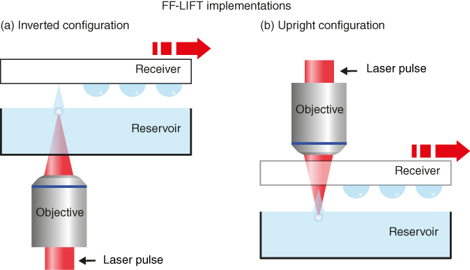
Figure 6.5 Schematic of two different implementations of FF-LIFT. (a) Inverted or forward configuration and (b) upright or backward configuration.
In the second configuration of FF-LIFT, known as backward, the liquid is ejected in the direction contrary to laser propagation. In particular, the laser beam first passes through the receiver substrate, it crosses the air gap between the receiver and the liquid film, and then it is focused beneath the liquid-free surface. Because the laser beam only travels through the liquid over a short distance, chromatic dispersion effects are significantly reduced compared to the forward implementation. In addition, the reservoir can be optically opaque without affecting the performance of the technique. In contrast, the receiver substrate must be transparent and present low chromatic dispersion. This strongly limits the potential use of FF-LIFT with many technologically significant substrates, such as silicon or metals, which are opaque but widely used in applications as relevant as lab-on-a-chip [2] or surface patterning [45]. Furthermore, the inevitable mismatch between the refractive index of air and that of the liquid will result in significant loss of intensity within the laser focal volume.
Considering the previous differences between the forward and backward configurations, what would be the suitable system to implement? This strongly depends on the particular demands of a given application. There is, though, an additional aspect that has not been discussed yet and that will probably determine the final system of choice for most users. In both forward and backward FF-LIFT, the reservoir has to be placed upside up. Consequently, the forward implementation requires a beam coming from below the reservoir, that is, an inverted optical system. This is more commonly found in life science laboratories. In contrast, the backward implementation needs an upright optical system, which is the standard system used for laser materials processing.
6.4.3 Spherical Aberration and Chromatic Dispersion
The focal point of a focusing lens (microscope objective) is usually designed to be an aplanatic point. In other words, the focus of most optical systems is designed to present minimal coma and spherical aberrations. However, if a planar dielectric with a different refractive index is placed within the optical path of the focusing length (between the lens and the focus), the aplanatic conditions are no longer fulfilled, and one can observe spherical aberration. The immediate consequence is the axial elongation of the focal volume. In FF-LIFT, the liquid plays the role of the dielectric, and hence, spherical aberration will have to be considered. Indeed, the elongation of the focal volume decreases the overall laser intensity and degrades the control in the positioning of cavitation bubble formation.
By using geometrical optics and Snell's law, it is possible to derive an expression for the lateral spherical aberration (As) induced by a planar dielectric. Considering As to be defined by the separation between the marginal and paraxial focus (the effective spreading of the focal volume) yields [74]:

where ![]() is the ratio of the refractive index of the medium (typically air) relative to the liquid,
is the ratio of the refractive index of the medium (typically air) relative to the liquid, ![]() is the physical distance travelled by the laser beam within the liquid (in the case of forward configuration, it should also include the thickness of the reservoir, considering it has the same refractive index as the liquid), and
is the physical distance travelled by the laser beam within the liquid (in the case of forward configuration, it should also include the thickness of the reservoir, considering it has the same refractive index as the liquid), and ![]() , with
, with ![]() being the beam waist at the entrance of the focusing lens with focal length
being the beam waist at the entrance of the focusing lens with focal length ![]() . Note that
. Note that ![]() is proportional to the numerical aperture (NA) of the focusing optics. From this equation, it can be observed that As scales with the NA of the system and with the distance the beam travels within the liquid (Table 6.2). Thus, the forward configuration will in general produce a more significant elongation of the focal volume than the backward layout. In addition, low NA optics will usually lead to better focus confinement, as experimentally demonstrated [61]. There exists, though, the possibility to greatly minimize spherical aberration in the forward configuration. This can be achieved by using a dipping objective, for example, a water-dipping objective. In this case, if both liquid and reservoir match the operational refractive index of the objective, for example, water, no spherical aberration would be induced.
is proportional to the numerical aperture (NA) of the focusing optics. From this equation, it can be observed that As scales with the NA of the system and with the distance the beam travels within the liquid (Table 6.2). Thus, the forward configuration will in general produce a more significant elongation of the focal volume than the backward layout. In addition, low NA optics will usually lead to better focus confinement, as experimentally demonstrated [61]. There exists, though, the possibility to greatly minimize spherical aberration in the forward configuration. This can be achieved by using a dipping objective, for example, a water-dipping objective. In this case, if both liquid and reservoir match the operational refractive index of the objective, for example, water, no spherical aberration would be induced.
Table 6.2 Spherical aberration As induced when focusing light using air microscope objectives with different NA and considering that a liquid with thickness d is placed before the system focus. In all cases, the liquid is assumed to be water, with a refractive index of 1.33.
| d (µm) | NA | |
| 100 | 0.3 | 1.6 |
| 400 | 0.3 | 6.3 |
| 1000 | 0.3 | 16 |
| 100 | 0.5 | 4.8 |
| 400 | 0.5 | 19 |
| 1000 | 0.5 | 48 |
Another important optical property of the medium that can affect the printing process is the refractive index dependency with wavelength. Indeed, the relative large wavelength bandwidth of femtosecond pulses makes them prone to chromatic dispersion, and consequent pulse stretching, when passing through different media. In addition, as a consequence of chromatic aberration, the effective intensity in the laser focus may be reduced. The chromatic dispersion of a medium is typically characterized with the Abbe number or constringence (symbol V), which specifies the variations in the refractive index of a medium for a specific spectral range. In particular, V = (nD−1)/(nF−nC), where nD, nF, and nC are the refractive indices of the material at the wavelengths 589.3, 486.1, and 656.3 nm, respectively. The Abbe number can be found in tables. Typically, materials with V < 50 are considered dispersive (V = 34 for polycarbonate plastics), whereas low-dispersive materials can reach V > 70, such as phosphate crown glasses. For water, V = 50, and hence, the amount of chromatic dispersion in FF-LIFT, particularly in the forward configuration, can be significant.
6.5 Applications
Traditional LIFT of liquids with a DRL is arguably the most widely used version of this printing approach. However, the possibility offered by FF-LIFT to decouple the requirements of the ink regarding the receiver substrate from those needed to prepare a liquid film could be advantageous in several fields. To illustrate the potential benefits of this technique, in this section, we present two selected examples of applications in which FF-LIFT can be successfully implemented.
6.5.1 Film-Free LIFT for Printing Biomaterials
A potential niche market for LIFT is the controlled deposition of biological materials such as DNA, [27, 75] proteins, [76–78], and even living cells [26, 28, 30, 37]. Compared to alternative strategies such as inkjet printing or pin spotting, LIFT offers unique features that render this technique particularly suitable for the growing fields of biomolecule microarrays or biosensors. Indeed, LIFT enables the printing of volumes as small as femtoliters while preserving a high throughput. In addition, it is possible to visually inspect the donor film during the printing process. This makes possible to irradiate only a targeted area of the donor film. For instance, if the donor film contains cells, one can select the cells to be ejected toward the receiver substrate. However, the problems related to the preparation of the liquid film are particularly excruciating in the case of biological materials. Notably, biological solutions are often transparent to the common laser radiations – the use of UV lasers is not recommended since it could alter the biological materials (e.g., denaturation of DNA) – and thus, an intermediate absorbing layer or DRL, usually a metal, is utilized to enhance the light absorption and induce liquid ejection. The use of an absorbing layer, though, can lead to sample contamination by micro/nanometallic particles. For instance, DNA damage and cell toxicity could be induced by metallic contaminants [79, 80]. Although the use of a polyimide intermediate layer, as in the case of blister-actuated LIFT, solves this problem [37] (Chapter 5), the risk of liquid dewetting for thin films prepared on polymers (Section 6.2.1.1) is very high, and hence, only specific materials with very low surface tension can be used in practice. Note that it is also possible to use ultrashort laser pulses in LIFT to induce material ejection from weakly absorbing materials without DRL. However, this option is difficult to implement in practice due to the small thickness of the liquid film and the refractive index mismatch between the ink and the carrier substrate. Indeed, in this case, the control of the laser focus beneath the free surface of the liquid film is utterly challenging not only due to spherical aberration and the intrinsic depth of field of the focusing optics (which also exist in FF-LIFT), but especially for the change (jump) in the focus position when traversing two materials each with a different refractive index.
Within this framework, the possibility offered by FF-LIFT to directly deposit the biological material from a reservoir is of clear advantage. Because no absorbing layer is needed, contamination can be greatly reduced. Moreover, by obviating the liquid film, one can save time, prevent potential contamination during the preparation of the liquid film, and more importantly, skip the tight requirements on the rheology of the ink necessary to obtain a spatiotemporal stable thin film. In fact, FF-LIFT could be used with liquids that present a relatively high vapor pressure, provided the laser focus beneath the free surface is adjusted to compensate for liquid evaporation. As stated in Section 6.2.1.1, such inks are incompatible with LIFT, since liquid evaporation can lead to dewetting issues.
The feasibility of FF-LIFT for the fabrication of miniaturized optical biosensors has been recently demonstrated [39]. In this case, the biosensor consisted of a microarray printed on a poly-l-lysine-coated microscope slide with FF-LIFT and containing mouse and rabbit immunoglobulin G (IgG) solutions (Figure 6.6a). Notably, both solutions were directly printed from a 100 µl cylindrical plastic container. After an immunoassay with tagged antibodies, fluorescence microscopy revealed high specific binding for each printed solution. This result demonstrates the ability of accurately placing undamaged proteins onto solid substrates using FF-LIFT. Furthermore, FF-LIFT has been successfully exploited for printing DNA molecules for a hybridization assay [39]. Two DNA solutions were printed by FF-LIFT, directly form a reservoir, each one containing a single human cDNA clone insert: the mitogen-activated protein kinase 3 gene (MAPK3) and the v-ets avian erythroblastosis virus E26 oncogenehomolog 2 (ETS2), respectively. After a standard hybridization protocol, with the complementary strands of the cDNAs tagged with a different fluorochrome (Cy5 for MAPK3 and Cy3 for ETS2), fluorescence images demonstrated the specific binding of each cDNA strand to its perfect complementary. This further confirms the feasibility of FF-LIFT for printing biomolecules.

Figure 6.6 Applications of FF-LIFT (a) Fluorescence image of a fabricated biosensors consisting of a microarray of mouse IgG and rabbit IgG after immunoassay with specific anti-IgG. The inset shows an optical microscopy image of the same array. (Duocastella et al. 2010 [39]. Reproduced from Elsevier.) (b) Laser printing applied to the realization of polymeric microlenses. Scanning electronic microscopy (SEM) images of polymer microlenses fabricated on (i) polydimethylsiloxane and (ii) glass. (iii) SEM image of a star-shaped pattern of microlenses. (iv) Optical microscopy image of the surface of a CD (line pitch 1.6 µm) without and with the microlens on top. In the latter, the lines of the CD can be observed, which demonstrates the effective enhancement in the resolution of the system.
(Florian et al. 2016 [51]. Reproduced from American Chemical Society.)
6.5.2 Film-Free LIFT for Micro-Optical Element Fabrication
The fabrication of micro-optical components plays a key role in the development of functional devices such as detectors, energy-harvesting systems, or CMOS cameras. With the advance of additive manufacturing processes and the trend toward customized production units, methods capable of directly fabricating user-defined microlenses or microlens arrays without masks or molds appear particularly suitable. Given the intrinsic compatibility of LIFT with highly viscous inks such as those traditionally used for microlens fabrication, this technique seems to be an ideal tool of choice for this purpose. In addition, the use of liquid printing techniques has a natural advantage over the methods that operate with solid materials, because surface tension provides liquid droplets with a perfectly spherical shape. This has prompted the use of LIFT for the successful printing of liquid microlenses that provide an enhancement of the focusing capabilities of a laser system and enable deep subwavelength laser nanopatterning [45]. Moreover, LIFT has recently been used for the fabrication of polymeric lenses with tailored geometry and size (Figure 6.6b) [51]. In both cases, the potential advantages of LIFT can be hampered by two serious constraints of this technique. First, the requirement of an absorbing layer can result in debris (micro/nanoparticles) inside the fabricated lens. As a result, the optical quality of the microlenses can be severely deteriorated. Second, the wettability of the microlenses with the receiver substrate dictates the optical properties of the lenses, namely the radius of curvature. Indeed, to obtain lenses with high curvature, one requires inks that present a poor wettability with the receiver substrate. Given the restricted number of available inks with desired optical qualities, an ink with poor wettability on the receiver will typically have poor wettability in most materials, and hence, the preparation of such an ink in film form will be challenging. In contrast, FF-LIFT has the potential to solve all these problems. Indeed, the possibility to generate micro-optical components without an absorbing layer can prevent contamination issues. Furthermore, printing inks with poor wettability is no longer a problem, because the ink can be directly handled from a reservoir or container.
6.6 Conclusions and Future Outlook
The use of FF-LIFT enables the printing of weakly absorbing liquids with high resolution and high speed over extended surfaces. The large experimental parameter space that comes with this technique is due to the possibility to directly deposit the liquid from a reservoir. This contrasts with traditional LIFT, in which the material of interest has to be spread into a thin film. Indeed, the outcome of LIFT is seriously affected by the spatial uniformity and temporal stability of the liquid donor film. As a consequence, LIFT is restricted to liquids with specific rheology, which may not be fully compatible with a targeted application.
The operational principle of FF-LIFT, based on cavitation jetting and corona formation, provides remote control of liquid ejection by simply tuning the laser parameters or the distance between the laser focus and the free surface. These unique characteristics can be exploited in a myriad of novel and fascinating applications such as biosensing, micro-optics, and tissue engineering. As FF-LIFT continues to be developed and we learn more about the fundamentals of liquid–laser interactions, interesting possibilities will continue to emerge, offering new opportunities for laser-based additive manufacturing technologies.
References
- 1 Mack, C.A. (2007) Fundamental Principles of Optical Lithography : the Science of Microfabrication, Wiley, Chichester, West Sussex, England; Hoboken, NJ.
- 2 Dittrich, P.S. and Manz, A. (2006) Lab-on-a-chip: microfluidics in drug discovery. Nat. Rev. Drug Discovery, 5 (3), 210–218.
- 3 Billiet, T., Vandenhaute, M., Schelfhout, J. et al. (2012) A review of trends and limitations in hydrogel-rapid prototyping for tissue engineering. Biomaterials, 33 (26), 6020–6041.
- 4 Mardis, E.R. (2008) Next-generation DNA sequencing methods. Annu. Rev. Genomics Hum. Genet., 9 (1), 387–402.
- 5 Menard, E., Meitl, M.A., Sun, Y. et al. (2007) Micro- and nanopatterning techniques for organic electronic and optoelectronic systems. Chem. Rev., 107 (4), 1117–1160.
- 6 Singh, M., Haverinen, H.M., Dhagat, P., and Jabbour, G.E. (2010) Inkjet printing-process and its applications. Adv. Mater., 22 (6), 673–685.
- 7 Piner, R.D., Zhu, J., Xu, F. et al. (1999) Dip-Pen Nanolithography. Science, 283 (5402), 661–663.
- 8 Quake, S.R. and Scherer, A. (2000) From micro- to nanofabrication with soft materials. Science, 290 (5496), 1536–1540.
- 9 Guo, L.J. (2007) Nanoimprint lithography: methods and material requirements. Adv. Mater., 19 (4), 495–513.
- 10 Arnold, C.B., Serra, P., and Piqué, A. (2007) Laser direct-write techniques for printing of complex materials. MRS Bull., 32, 23–31.
- 11 Delaporte, P. and Alloncle, A.-P. (2016) Laser-induced forward transfer: a high resolution additive manufacturing technology. Opt. Laser Technol., 78, 33–41.
- 12 Wang, J., Auyeung, R.C.Y., Kim, H. et al. (2010) Three-dimensional printing of interconnects by laser direct-write of silver nanopastes. Adv. Mater., 22 (40), 4462–4466.
- 13 Kim, H., Duocastella, M., Charipar, K.M. et al. (2013) Laser printing of conformal and multi-level 3D interconnects. Appl. Phys. A, 113 (1), 5–8.
- 14 Willis, D.A. and Grosu, V. (2005) Microdroplet deposition by laser-induced forward transfer. Appl. Phys. Lett., 86 (24), 244103.
- 15 Banks, D.P., Grivas, C., Mills, J.D. et al. (2006) Nanodroplets deposited in microarrays by femtosecond Ti : sapphire laser-induced forward transfer. Appl. Phys. Lett., 89 (19), 193107.
- 16 Tseng, M.L., Wu, P.C., Sun, S. et al. (2012) Fabrication of multilayer metamaterials by femtosecond laser-induced forward-transfer technique. Laser Photonics Rev., 6 (5), 702–707.
- 17 Surdo, S., Piazza, S., Ceseracciu, L. et al. (2016) Towards nanopatterning by femtosecond laser ablation of pre-stretched elastomers. Appl. Surf. Sci., 374 (30), 151–156.
- 18 Heisterkamp, A., Maxwell, I.Z., Mazur, E. et al. (2005) Pulse energy dependence of subcellular dissection by femtosecond laser pulses. Opt. Express, 13 (10), 3690–3696.
- 19 Boyden, E.S., Zhang, F., Bamberg, E. et al. (2005) Millisecond-timescale, genetically targeted optical control of neural activity. Nat. Neurosci., 8 (9), 1263–1268.
- 20 Antkowiak, M., Torres-Mapa, M.L., Stevenson, D.J. et al. (2013) Femtosecond optical transfection of individual mammalian cells. Nat. Protoc., 8 (6), 1216–1233.
- 21 Heller, M.J. (2002) DNA microarray technology: devices, systems, and applications. Annu. Rev. Biomed. Eng., 4 (1), 129–153.
- 22 Hall, D.A., Ptacek, J., and Snyder, M. (2007) Protein microarray technology. Mech. Ageing Dev., 128 (1), 161–167.
- 23 Wang, J. (2005) Carbon-nanotube based electrochemical biosensors: a review. Electroanalysis, 17 (1), 7–14.
- 24 Fan, X., White, I.M., Shopova, S.I. et al. (2008) Sensitive optical biosensors for unlabeled targets: a review. Anal. Chim. Acta, 620 (1–2), 8–26.
- 25 Hopp, B., Smausz, T., Antal, Z. et al. (2004) Absorbing film assisted laser induced forward transfer of fungi (Trichoderma conidia). J. Appl. Phys., 96 (6), 3478–3481.
- 26 Hopp, B., Smausz, T., Kresz, N. et al. (2005) Survival and proliferative ability of various living cell types after laser-induced forward transfer. Tissue Eng., 11 (11–12), 1817–1823.
- 27 Fernández-Pradas, J.M., Colina, M., Serra, P. et al. (2004) Laser-induced forward transfer of biomolecules. Thin Solid Films, 453–454, 27–30.
- 28 Guillotin, B., Souquet, A., Catros, S. et al. (2010) Laser assisted bioprinting of engineered tissue with high cell density and microscale organization. Biomaterials, 31 (28), 7250–7256.
- 29 Guillotin, B. and Guillemot, F. (2011) Cell patterning technologies for organotypic tissue fabrication. Trends Biotechnol., 29 (4), 183–190.
- 30 Barron, J.A., Wu, P., Ladouceur, H.D., and Ringeisen, B.R. (2004) Biological laser printing: a novel technique for creating heterogeneous 3-dimensional cell patterns. Biomed. Microdevices, 6 (2), 139–147.
- 31 Barron, J.A., Ringeisen, B.R., Kim, H. et al. (2004) Application of laser printing to mammalian cells. Thin Solid Films, 453–454, 383–387.
- 32 Dinca, V., Farsari, M., Kafetzopoulos, D. et al. (2008) Patterning parameters for biomolecules microarrays constructed with nanosecond and femtosecond UV lasers. Thin Solid Films, 516 (18), 6504–6511.
- 33 Fardel, R., Nagel, M., Nüesch, F. et al. (2007) Laser forward transfer using a sacrificial layer: Influence of the material properties. Appl. Surf. Sci., 254 (4), 1322–1326.
- 34 Banks, D.P., Kaur, K., Gazia, R. et al. (2008) Triazene photopolymer dynamic release layer-assisted femtosecond laser-induced forward transfer with an active carrier substrate. Europhys. Lett. Assoc., 83 (3), 38003.
- 35 Brown, M.S., Kattamis, N.T., and Arnold, C.B. (2011) Time-resolved dynamics of laser-induced micro-jets from thin liquid films. Microfluid. Nanofluid., 11 (2), 199–207.
- 36 Brown, M.S., Brasz, C.F., Ventikos, Y., and Arnold, C.B. (2012) Impulsively actuated jets from thin liquid films for high-resolution printing applications. J. Fluid Mech., 709, 341–370.
- 37 Kattamis, N.T., Purnick, P.E., Weiss, R., and Arnold, C.B. (2007) Thick film laser induced forward transfer for deposition of thermally and mechanically sensitive materials. Appl. Phys. Lett., 91 (17), 171120.
- 38 Duocastella, M., Patrascioiu, A., Fernández-Pradas, J.M. et al. (2010) Film-free laser forward printing of transparent and weakly absorbing liquids. Opt. Express, 18 (21), 21815–21825.
- 39 Duocastella, M., Fernández-Pradas, J.M., Morenza, J.L. et al. (2010) Novel laser printing technique for miniaturized biosensors preparation. Sens. Actuators, B, 145 (1), 596–600.
- 40 Craster, R.V. and Matar, O.K. (2009) Dynamics and stability of thin liquid films. Rev. Mod. Phys., 81 (3), 1131–1198.
- 41 Bestehorn, M. and Merkt, D. (2006) Regular surface patterns on Rayleigh-Taylor unstable evaporating films heated from below. Phys. Rev. Lett., 97 (12), 127802.
- 42 Bonn, D., Eggers, J., Indekeu, J., and Meunier, J. (2009) Wetting and spreading. Rev. Mod. Phys., 81 (2), 739–805.
- 43 H-C, Chang (1994) Wave evolution on a falling film. Annu. Rev. Fluid Mech., 26 (1), 103–136.
- 44 de Gennes, P.-G., Brochard-Wyart, F., and Quéré, D. (2004) Capillarity and Wetting Phenomena, Springer-Verlag, New York, Inc.
- 45 Duocastella, M., Florian, C., Serra, P., and Diaspro, A. (2015) Sub-wavelength laser nanopatterning using droplet lenses. Sci. Rep., 5, 16199.
- 46 Duocastella, M., Fernández-Pradas, J.M., Morenza, J.L., and Serra, P. (2010) Sessile droplet formation in the laser-induced forward transfer of liquids: A time-resolved imaging study. Thin Solid Films, 518, 5321–5325.
- 47 Brasz, C.F., Yang, J.H., and Arnold, C.B. (2014) Tilting of adjacent laser-induced liquid jets. Microfluid. Nanofluid., 18 (2), 185–197.
- 48 Biver, E., Rapp, L., Alloncle, A.-P. et al. (2014) High-speed multi-jets printing using laser forward transfer: time-resolved study of the ejection dynamics. Opt. Express, 22 (14), 17122–17134.
- 49 Hall, D.B., Underhill, P., and Torkelson, J.M. (1998) Spin coating of thin and ultrathin polymer films. Polym. Eng. Sci., 38 (12), 2039–2045.
- 50 Scriven, L.E. (1988) Physics and Applications of Dip Coating and Spin Coating. MRS Online Proc. Libr., 121, 717–729.
- 51 Florian, C., Piazza, S., Diaspro, A. et al. (2016) Direct laser printing of tailored polymeric microlenses. ACS Appl. Mater. Interfaces, 8 (27), 17028–17032.
- 52 Duocastella, M., Fernández-Pradas, J.M., Morenza, J.L., and Serra, P. (2011) Droplet printing through bubble contact in the laser forward transfer of liquids. Appl. Surf. Sci., 257 (7), 2825–2829.
- 53 Delville, J.-P., Robert de Saint Vincent, M., Schroll, R.D. et al. (2009) Laser microfluidics: fluid actuation by light. J. Opt. A: Pure Appl. Opt., 11 (3), 034015.
- 54 Vogel, A., Noack, J., Nahen, K. et al. (1999) Energy balance of optical breakdown in water at nanosecond to femtosecond time scales. Appl. Phys. B, 68 (2), 271–280.
- 55 Vogel, A., Nahen, K., Theisen, D., and Noack, J. (1996) Plasma formation in water by picosecond and nanosecond Nd:YAC laser pulses – Part I: Optical breakdown at threshold and superthreshold irradiance. IEEE J. Sel. Top. Quantum Electron., 2 (4), 847–860.
- 56 Vogel, A., Busch, S., and Parlitz, U. (1996) Shock wave emission and cavitation bubble generation by picosecond and nanosecond optical breakdown in water. J. Acoust. Soc. Am., 100 (1), 148–165.
- 57 Schaffer, C.B., Nishimura, N., Glezer, E.N. et al. (2002) Dynamics of femtosecond laser-induced breakdown in water from femtoseconds to microseconds. Opt. Express, 10 (3), 196–203.
- 58 Robinson, P.B., Blake, J.R., Kodama, T. et al. (2001) Interaction of cavitation bubbles with a free surface. J. Appl. Phys., 89 (12), 8225–8237.
- 59 Pearson, A., Cox, E., Blake, J.R., and Otto, S.R. (2004) Bubble interactions near a free surface. Eng. Anal. Boundary Elem., 28 (4), 295–313.
- 60 Patrascioiu, Fernandez-Pradas, J. M., Palla-Papavlu, et al. (2014) Laser-generated liquid microjets : correlation between bubble dynamics and liquid ejection. Microfluid. Nanofluid., 16 (1–2), 55–63.
- 61 Desrus, H., Chassagne, B., Moizan, F. et al. (2016) Effective parameters for film-free femtosecond laser assisted bioprinting. Appl. Opt., 55 (14), 3879–3886.
- 62 Koukouvinis, P., Gavaises, M., Supponen, O., and Farhat, M. (2016) Simulation of bubble expansion and collapse in the vicinity of a free surface. Phys. Fluids, 28 (5), 051203.
- 63 Eggers, J. and Villermaux, E. (2008) Physics of liquid jets. Rep. Prog. Phys., 71 (3), 036601.
- 64 Duocastella, M., Fernández-Pradas, J.M., Serra, P., and Morenza, J.L. (2008) Jet formation in the laser forward transfer of liquids. Appl. Phys. A, 93 (2), 453–456.
- 65 Duocastella, M., Patrascioiu, A., Dinca, V. et al. (2011) Study of liquid deposition during laser printing of liquids. Appl. Surf. Sci., 257 (12), 5255–5258.
- 66 Boutopoulos, C., Kalpyris, I., Serpetzoglou, E., and Zergioti, I. (2014) Laser-induced forward transfer of silver nanoparticle ink: Time-resolved imaging of the jetting dynamics and correlation with the printing quality. Microfluid. Nanofluid., 16 (3), 493–500.
- 67 Brown, M.S., Kattamis, N.T., and Arnold, C.B. (2010) Time-resolved study of polyimide absorption layers for blister-actuated laser-induced forward transfer. J. Appl. Phys., 107 (8), 083103.
- 68 Unger, C., Gruene, M., Koch, L. et al. (2011) Time-resolved imaging of hydrogel printing via laser-induced forward transfer. Appl. Phys. A, 103 (2), 271–277.
- 69 Gruene, M., Unger, C., Koch, L. et al. (2011) Dispensing pico to nanolitre of a natural hydrogel by laser-assisted bioprinting. Biomed. Eng. Online, 10 (1), 19.
- 70 Yan, J., Huang, Y., Xu, C., and Chrisey, D.B. (2012) Effects of fluid properties and laser fluence on jet formation during laser direct writing of glycerol solution. J. Appl. Phys., 112 (8), 083105.
- 71 Zhang, Z., Xiong, R., Mei, R. et al. (2015) Time-resolved imaging study of jetting dynamics during laser printing of viscoelastic alginate solutions. Langmuir, 31 (23), 6447–6456.
- 72 Vogel, A., Linz, N., Freidank, S., and Paltauf, G. (2008) Femtosecond-laser-induced nanocavitation in water: Implications for optical breakdown threshold and cell surgery. Phys. Rev. Lett., 100 (3), 038102.
- 73 Patrascioiu, A., Duocastella, M., Fernández-Pradas, J.M. et al. (2011) Liquids microprinting through a novel film-free femtosecond laser based technique. Appl. Surf. Sci., 257 (12), 5190–5194.
- 74 Iwaniuk, D., Rastogi, P., and Hack, E. (2011) Correcting spherical aberrations induced by an unknown medium through determination of its refractive index and thickness. Opt. Express, 19 (20), 19407–19414.
- 75 Colina, M., Serra, P., Fernández-Pradas, J.M. et al. (2005) DNA deposition through laser induced forward transfer. Biosens. Bioelectron., 20, 1638–1642.
- 76 Zergioti, I., Karaiskou, A., Papazoglou, D.G. et al. (2005) Femtosecond laser microprinting of biomaterials. Appl. Phys. Lett., 86 (16), 163902.
- 77 Serra, P., Fernández-Pradas, J.M., Berthet, F.X. et al. (2004) Laser direct writing of biomolecule microarrays. Appl. Phys. A, 79 (4–6), 949–952.
- 78 Duocastella, M., Fernández-Pradas, J.M., Domínguez, J. et al. (2008) Printing biological solutions through laser-induced forward transfer. Appl. Phys. A, 93 (4), 941–945.
- 79 Papageorgiou, I., Brown, C., Schins, R. et al. (2007) The effect of nano- and micron-sized particles of cobalt-chromium alloy on human fibroblasts in vitro. Biomaterials, 28 (19), 2946–2958.
- 80 Kroll, A., Pillukat, M.H., Hahn, D., and Schnekenburger, J. (2009) Current in vitro methods in nanoparticle risk assessment: Limitations and challenges. Eur. J. Pharm. Biopharm., 72 (2), 370–377.