Chapter 9
Laser-Induced Forward Transfer of Soft Materials
Zhengyi Zhang1,2, Ruitong Xiong2 and Yong Huang2
1Huazhong University of Science and Technology, School of Naval Architecture and Ocean Engineering, 1037 Luoyu Road, Wuhan, Hubei, 430074, China
2University of Florida, Department of Mechanical and Aerospace Engineering, 571 Gale Lemerand Drive, Gainesville, FL, 32611, USA
9.1 Introduction
Laser-induced forward transfer (LIFT), a versatile direct-write technique to deposit materials, has emerged as a promising orifice-free direct-write technique with a great variety of applications, such as microelectronics [1] and tissue engineering [2–9], to name a few. In particular, it has found increasing interest in printing two-dimensional (2D) or three-dimensional (3D) soft tissue constructs from soft materials [4, 10]. During LIFT, a laser beam passes through one side of a support, which is transparent to the laser beam and coated with a thin layer of soft build material to be printed on the other side. Sometimes, a sacrificial layer of energy-absorbing material is also coated between the support and the build material layer. Collectively, they are usually called the laser printing ribbon. The incident laser beam is focused on the interface between the support and the coating and sublimes part of the coating material, resulting in a high-temperature, high-pressure vapor or plasma bubble due to rapid localized heating. The bubble further expands and may eject some of the underneath coating material away from the quartz support as a liquid jet. Depending on the laser fluence and coating's rheological properties, the resulting jet may become a long, thin jet and then breakup into one or a few droplets or recoil back to the coating.
During a typical LIFT-based fabrication process [11], each structure is made in a voxel-by-voxel, then layer-by-layer manner. Within a given layer, each continuous feature is made of a number of printed droplets. The shape and size of printed droplets are largely affected by the properties of materials being transferred and/or operating conditions [12–14] and is ultimately determined by the jet formation process. As such, it is important to understand and further model the jet and droplet formation processes and the droplet landing/spreading process under different LIFT operating conditions when various electronic or biological soft build materials are printed. This will allow a better understanding of the LIFT process as well as a better control of the resulting printing quality and feature resolution, laying down a solid foundation for the fabrication of functional 2D or 3D tissues using laser printing.
While the general jet formation and droplet deposition mechanisms have been discussed in Chapter 4, herein the effects of fluid properties and laser fluence on the jet formation process are reported during LIFT of soft materials, which include Newtonian glycerol and viscoelastic alginate solutions herein. Under identified optimal printing conditions, the feasibility of using laser printing for the freeform fabrication of 3D alginate and cellular tubes is further investigated, which can be considered as the first logical step toward successful organ printing.
9.2 Background
The jet formation mechanism in laser printing has been studied using time-resolved imaging analysis [15–18]. Depending on the applied laser fluence, three distinct working regimes have been identified: subthreshold (no material deposition), jetting (having well-defined jet formation), and plume (generating atomized droplets) [12, 16, 19, 20]. The well-defined jet formation regime is generally desired for better printing or direct writing. During this process, a bubble is first generated by absorbing the energy of the incident laser pulse, and then a needle-like jet is formed as the bubble expands, and finally, a long, thin jet is developed. In addition, some phenomena may accompany the formation of the well-defined jet: for example, the formation of a counter-jet inside the ribbon coating [16], a bulgy structure due to the possible lateral collapse of the jet [18], or droplets after jet breakup [21].
Jet morphology has been characterized in terms of the bubble size [21], jet diameter [16, 18], and jet breakup [18, 21]. Specifically, the effects of laser fluence on the jet morphology and jet velocity have been studied [16, 18, 19, 22], and the jet and plume velocities were found to increase with the laser fluence [16, 19]. In addition, the jet formation process has been evaluated under various operating conditions such as the sacrificial layer thickness [21], ribbon coating thickness [23], direct-writing height [15, 24], and laser beam dimensions [13, 21]. However, the investigation about the effects of fluid properties as well as the combined effects of laser fluence and fluid properties on the jet formation process is still largely elusive. In this study, time-resolved imaging analysis has been applied to investigate the individual and combined effects of fluid properties and laser fluence on the jet formation process to have a comprehensive understanding of the LIFT technology.
With the capability of printing various soft materials, laser printing has been implemented for the fabrication of 2D or 3D constructs/structures from various biomaterials as well as cellular bioinks [4, 10]. Some interesting 2D constructs include 2D branch and stem structures made from human umbilical vein endothelial cells (HUVECs) and human umbilical vein smooth muscle cells (HUVSMCs) to investigate the interaction between these two cells [25], and 2D chessboard-like cardiac patch comprised of HUVECs and human mesenchymal stem cells (hMSCs) for cardiac regeneration [26]. While 3D constructs are of ultimate interest, only few studies have been reported regarding the freeform fabrication of complex and spatially heterogeneous 3D patterns. Multilayer hydrogel-cell planar structure has been fabricated by laser printing human adipose-derived stem cells (ASCs) and endothelial colony-forming cells (ECFCs), as individual droplets onto hyaluronic acid–fibrinogen hydrogel layer and then covered with another hydrogel layer to study cell–cell and cell–environment interactions [8]. Skin-like structure has been made by laser printing collagen-based NIH 3T3 fibroblast and human immortalized keratinocyte coatings to fabricate multilayered (with alternating cellular layers) and grid structures to investigate cell functions and tissue formation process in a 3D environment [27]. However, these structures are still not strictly 3D in nature, and there were no arbitrary material or geometry variations along the height direction. Toward 3D laser bioprinting, Yan et al. [11] and Xiong et al. [28] have attempted to laser print tubular alginate structures with some success, but the approach is yet to be further implemented for cellular construct fabrication.
9.3 Jetting Dynamics during Laser Printing of Soft Materials
To have a better understanding of the jetting dynamics during laser printing, the jet/droplet formation process during the laser printing of representative Newtonian glycerol and viscoelastic alginate bioinks has been investigated. The effects of the operating conditions such as the laser fluence and material properties (e.g., the glycerol/alginate concentration) on the jet formation performance have been evaluated. The glycerol and alginate solutions were selected as representative bioinks for their many fabrication applications. As shown in Figure 9.1, the LIFT apparatus had a laser delivery system, an argon fluoride (ArF) excimer laser (193 nm, 12 ns pulse duration, Coherent ExciStar, Santa Clara, CA), and a ribbon, which consisted of a quartz disk (Edmund optics, Barrington, NJ) and a thin layer of glycerol/alginate ink coating to be printed. The laser spot size was controlled at 150 µm in diameter, and its repetition rate was set as at 2 Hz. Laser fluence was measured and reported after considering a 15% transmission loss due to the quartz disk. The jet/droplet formation process was studied using a JetXpert imaging system (ImageXpert Inc., Nashua, NH) based on a time-resolved imaging method. After each laser firing, the trigger signal from the laser was used to control the imaging system in order to capture a frame of a droplet formation process after a certain delay time. For a given printing scenario, a series of images were taken using different delay times of different jets and compiled to represent the jet and droplet formation process.
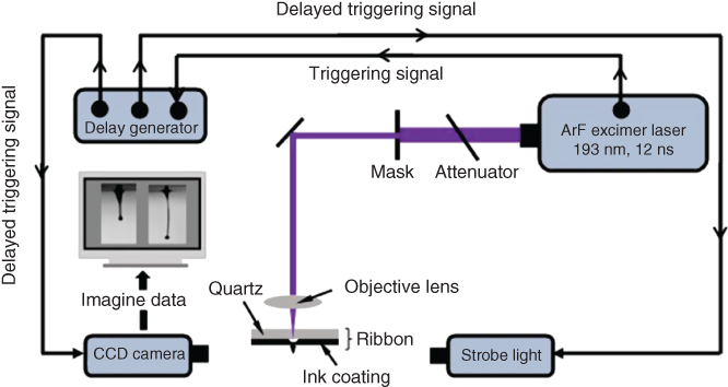
Figure 9.1 Schematic of experimental setup.
(Zhang et al. 2015 [29]. Reproduced with permission of American Chemical Society.)
9.3.1 Jet Formation Dynamics during Laser Printing of Newtonian Glycerol Solutions
Glycerol (Acros Organics, Fair Lawn, NJ, 99% pure) and deionized (DI) water were used to make the glycerol–water coating inks with different glycerol concentrations (v/v). The coating ink was controlled to be 100 µm. As shown in Table 9.1, two laser printing experiments have been conducted to appreciate the effects of laser fluence and glycerol concentration on the jetting dynamics, respectively.
Table 9.1 Design of experiments
| Experiment no. | Glycerol concentration (v/v) | Laser fluence (mJ/cm2) |
| 1 | 15%, 25%, 35%, 50%, 65%, 75%, 85%, and 99% | 717, 957, 1183, and 1433 |
| 2 | 15%, 25%, 35%, 50%, 65%, 75%, 85%, and 99% | 717 |
9.3.1.1 Typical Jetting Regimes
Time-resolved imaging analysis was performed in this study to obtain a better understanding of the material transfer process during LIFT. Several events occur during a typical LIFT process: bubble formation, jet formation/breakup, and jet/droplet landing. During the direct-write process, the energy of the incident laser pulse is absorbed by the glycerol solution in the ribbon coating, producing a high-pressure and high-temperature bubble that further expands within the coating due to sublimation [12, 30]. Well-defined jets only form under certain operating conditions for a given glycerol solution. In particular, the jet formation process can be classified into four different scenarios depending on the laser fluence and the glycerol concentration: pluming/splashing (Figure 9.2), jetting with a bulgy shape (Figure 9.3a,b), well-defined jetting (9.3c,d), and no material transfer (Figure 9.3e). The background of these figures is composed of two different regions: the top portion corresponds to the ribbon and its coating and the lower part to the free space or ambient environment. There were some reflections of jetting phenomena on the ribbon, which acted as a mirror during imaging. The phenomena observed herein when the concentration changed are consistent with others reported or discussed when operating conditions varied [12, 16, 19, 20] during laser printing.
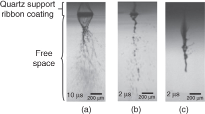
Figure 9.2 Pluming/splashing regime images obtained using low glycerol concentration solutions: (a) 15%, (b) 25%, and (c) 35%, all of them at a laser fluence of 717 mJ/cm2.
(Yan et al. 2012 [31]. Reproduced with permission of American Institute of Physics.)

Figure 9.3 Different time-resolved images of some jetting regimes (laser fluence of 717 mJ/cm2): (a) jetting with a bulgy shape when using 50% glycerol solution, (b) jetting with a bulgy shape when using 65% solution, (c) well-defined jetting when using 75% solution, (d) well-defined jetting when using 85% solution, and (e) no material transfer when using 99% solution.
(Yan et al. 2012 [31]. Reproduced with permission of American Institute of Physics.)
9.3.1.2 Jetting Regime as Function of Fluid Properties and Laser Fluence
Jetting during LIFT is the result of the formation of a laser-induced vapor/plasma bubble inside the ribbon coating. As the absorbed laser energy raises the solution temperature in the laser focal volume above the boiling temperature, the heated fluidic coating material undergoes a metastable superheated state [32]. Any slight perturbation in the coating density may lead to the initiation of vapor nuclei in the superheated liquid, known as homogeneous nucleation; once vapor bubbles reach a critical size, their further growth is spontaneous and the superheated volume may explode [33], leading to phase explosion, a form of rapid evaporation. When the internal bubble pressure reaches a balance with that due to the ambient pressure and the surface tension, the bubble has its largest size. As the bubble continues to grow, the internal bubble pressure becomes lower than that due to the ambient environment and surface tension. Then it shrinks and eventually collapses.
In this study, it is considered that the laser pulse-induced phase explosion mostly contributes to the generation of vapor pressure, which ejects the coating material beneath to form a jet or jets. It should be pointed out that laser-induced thermoelastic stress [34] might also contribute to the jet formation in addition to phase explosion. The aforementioned scenario is also applicable to the sacrificial LIFT process, during which the bubble is induced by the expansion of a vapor or plasma resulting from the ablation of sacrificial film [35, 36].
The effect of glycerol concentration is shown in Figure 9.3 by printing different concentration glycerol solutions under a laser fluence of 717 mJ/cm2. For the highest concentration solution (99%), the bubble pressure is not high enough to overcome the effect due to the ambient pressure and the surface tension, so no material is transferred. For the 85% and 75% solutions, a well-defined jet forms. The expanding bubble collapses outwards the coating instead of shrinking or collapsing inwards the coating. For the 65% and 50% solutions, a jet may form but with bulge(s) around it. As the laser-induced bubble expands, a high-pressure area forms between the bubble and the free surface. The formation of bulges is attributed to the collision of the liquid flows around the ablation spot [18] and/or the breakup of the main bubble when vapor bubble collapses inwards and/or bursts outwards the coating. This phenomenon is analogous to the evolution of cavitation bubble during ablation in liquid [37, 38]. For the 35%, 25%, and 15% solutions, splashing and bubble bursting clearly reveal the effect of a highly pressurized bubble, which bursts outwards the coating and even may atomize the coating being transferred.
The effect of laser fluence on the jet formation has also been studied herein, and similar phenomena have been observed as previously reported [16, 18, 19, 22]. Figure 9.4 shows some representative jetting regimes during LIFT using a 65% glycerol solution. Four jet formation regimes were also observed: no material transferring, well-defined jetting, jetting with a bulgy shape, and pluming/splashing as the applied laser fluence increased. The laser fluence determines the jet kinetic energy, and higher laser fluences result in a higher jet/droplet velocity [16, 19, 39]. The glycerol concentration affects the viscous dissipation energy and the capillary force. When the jet kinetic energy is higher than that due to viscous dissipation, a jet forms; when the surface tension effect dominates and leads to the Rayleigh instability, the jet breaks up, forming flying droplet(s).
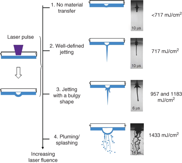
Figure 9.4 Jetting regimes during LIFT under different laser fluences (65% glycerol solution).
(Yan et al. 2012 [31]. Reproduced with permission of American Institute of Physics.)
Under laser fluences lower than 717 mJ/cm2 such as 478 mJ/cm2, no material was transferred, and the bubble pressure did not exceed the pressure due to the surface tension of the ribbon coating and the ambient environment. This is a similar scenario as shown in Figure 9.3e. Under a laser fluence of 717 mJ/cm2, a well-defined jet formed, as shown in Figure 9.3c,d. Under laser fluences of 957 and 1183 mJ/cm2, the forming jet turned bulgy and curved as seen from Figure 9.3a,b. The higher the laser fluence, the more the coating material being transferred, resulting in a larger but less stable jet. When the applied laser fluence was even higher, such as 1433 mJ/cm2, splashing occurred instead of a jet, similar to those shown in Figure 9.2. It should be noted that the laser fluence threshold for different jetting regimes varies as the coating solution changes.
In summary, jetting dynamics is a function of fluid properties such as the glycerol concentration and operating conditions such as the laser fluence. If the laser fluence is too low and/or the glycerol concentration is too high, it is less likely for a bubble to fully form and/or grow before it collapses [32]. There is no enough kinetic energy provided by the expanding bubble. Even when a jet can be formed, it retracts back after the bubble collapses. If the laser fluence is too high and/or the glycerol concentration is too low, it is also difficult to form a well-developed jet since dramatic bubble expansion may lead to a bulgy shape [40] and even splashing [12, 18, 32]. Only under some selected conditions of glycerol concentration and laser fluence, as aforementioned, can a well-defined jet form.
9.3.1.3 Jettability Phase Diagram
Generally, the droplet formation process on the printing quality has been of great research interest during dropwise manufacturing, especially in terms of the printability [41] and the droplet formability [42, 43] during orifice-based jetting. During the jet/droplet formation process, capillary thinning and breakup of the free surface liquid filaments can be characterized by three main timescales: visco-capillary timescale ![]() , inertio-capillary or Rayleigh timescale
, inertio-capillary or Rayleigh timescale ![]() , and
, and ![]() , where
, where ![]() is the zero-shear viscosity, R is the characteristic length, which is taken as the laser spot radius in this study (75 µm),
is the zero-shear viscosity, R is the characteristic length, which is taken as the laser spot radius in this study (75 µm), ![]() is the surface tension, ρ is the density, and
is the surface tension, ρ is the density, and ![]() is the longest relaxation time, which is a characteristic time that relates to the motion of the polymer chains. For most viscoelastic soft materials, three material property-based dimensionless numbers can be derived based on the relative significance of these three timescales: the Ohnesorge number
is the longest relaxation time, which is a characteristic time that relates to the motion of the polymer chains. For most viscoelastic soft materials, three material property-based dimensionless numbers can be derived based on the relative significance of these three timescales: the Ohnesorge number ![]() , the elasto-capillary number
, the elasto-capillary number ![]() , and the intrinsic Deborah number
, and the intrinsic Deborah number ![]() . The Oh number represents the ratio of the viscous to inertial effects, and the De0 or Ec number represents the elastic to viscous or inertial effects. It should be pointed out that the Ec number is a De0 number with a characteristic process time of
. The Oh number represents the ratio of the viscous to inertial effects, and the De0 or Ec number represents the elastic to viscous or inertial effects. It should be pointed out that the Ec number is a De0 number with a characteristic process time of ![]() for viscous-effect-dominated fluids.
for viscous-effect-dominated fluids.
For the breakup of Newtonian glycerol solutions, the elastic effects are negligible, and their jetting dynamics can be conveniently captured by the Ohnesorge number (Oh) solely [44]. It is noted that the Ohnesorge number only depends on the thermophysical properties (viscosity, density, and surface tension) of the fluid and the laser spot size.
As discussed, a good jet only forms under certain combinations of fluid properties and operating conditions. For given operating conditions such as the laser fluence in this study, a new nondimensional J number ![]() , defined as the inverse of the Ohnesorge number, is proposed to evaluate the jettability during laser printing. It is noted that the inverse of the Ohnesorge number has also been proposed as a nondimensional Z number to quantify the fluid printability during inkjetting under a certain excitation voltage, and the printability was evaluated based on the single droplet formability, minimum stand-off distance (distance between the nozzle and the receiving substrate), positional accuracy, and maximum allowable jetting frequency [41]. Alternatively, J can also be interpreted as
, defined as the inverse of the Ohnesorge number, is proposed to evaluate the jettability during laser printing. It is noted that the inverse of the Ohnesorge number has also been proposed as a nondimensional Z number to quantify the fluid printability during inkjetting under a certain excitation voltage, and the printability was evaluated based on the single droplet formability, minimum stand-off distance (distance between the nozzle and the receiving substrate), positional accuracy, and maximum allowable jetting frequency [41]. Alternatively, J can also be interpreted as ![]() , the ratio between the inertio-capillary or Rayleigh timescale
, the ratio between the inertio-capillary or Rayleigh timescale ![]() and visco-capillary timescale
and visco-capillary timescale ![]() .
.
Figure 9.5 illustrates the relationships among J, the visco-capillary and Rayleigh timescales, and the glycerol concentration under a laser fluence of 717 mJ/cm2. As the glycerol concentration increases, the viscosity increases significantly while there are negligible variations in density and surface tension [12], resulting in a decreasing J. Due to the same reason, the visco-capillary timescale increases significantly while the Rayleigh timescale almost stays the same as the glycerol concentration decreases. As seen from Figure 9.5, at most time, no materials are transferred if the visco-capillary timescale is longer than the Rayleigh timescale. Once the visco-capillary timescale is smaller than the Rayleigh timescale with an 85% glycerol solution, well-defined jet forms; if the glycerol concentration further decreases, splashing may happen. As the J value decreases almost exponentially with the glycerol concentration, it is observed that a good jet forms at 0.09 ≤J ≤ 1.76 (corresponding to 75–85%) in this study under the laser fluence of 717 mJ/cm2.
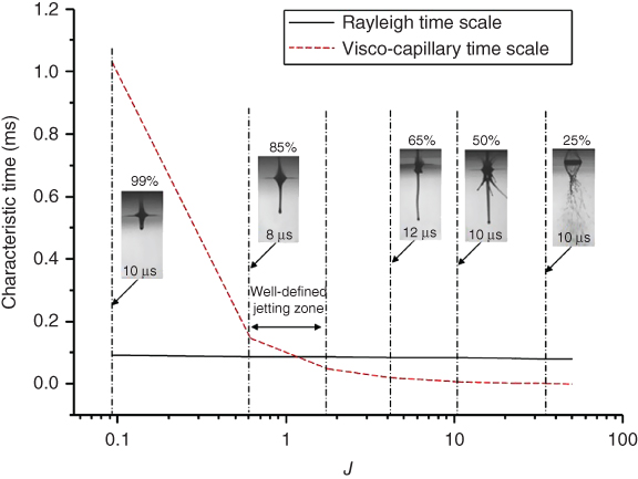
Figure 9.5 Jetting regimes and characteristic timescale variations versus the dimensionless parameter J under a laser fluence of 717 mJ/cm2.
(Yan et al. 2012 [31]. Reproduced with permission of American Institute of Physics.)
It should be noted that the jettability range varies as the laser fluence changes, which means the change of external forcing dynamics such as the jet velocity. Figure 9.6 illustrates different jetting regimes (no materials transferred, good jet forming, and splashing/bulgy) delineated using dashed lines based on the experimental observations in this study as the laser fluence varies. Figure 9.6a is based on the jettability number, J, while Figure 9.6b is based on the glycerol concentration. The dashed lines are for illustration only, and more experiments are needed in future studies to exactly determine the line positions. To better appreciate the jettability, a nondimensional number-based phase diagram, such as a diagram based on the Ohnesorge and Reynolds numbers for typical viscous fluids [44], is required by including the contributions from both the material properties and operating conditions.
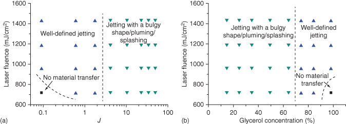
Figure 9.6 The influence of glycerol concentration and laser fluence on jet morphology and printability (dashed lines are for illustration only).
(Yan et al. 2012 [31]. Reproduced with permission of American Institute of Physics.)
9.3.2 Jet Formation Dynamics during Laser Printing of Viscoelastic Alginate Solutions
9.3.2.1 Ink Coating Preparation and Design of Experiments
Sodium alginate (Sigma–Aldrich, St. Louis, MO) was dissolved in the deionized water to make coating inks with different alginate concentrations of 2%, 4%, 6%, and 8% (w/v). The material properties of the alginate solutions are shown in Table 9.2. Specifically, the shear viscosity was measured using a cup-and-bob rheometer (ARES, TA Instrument, New Castle, DE), and the surface tension was measured using a pendant drop method (DSA10-MK2, Krüss GmbH, Hamburg, Germany). The longest relaxation time was determined based on the elasto-capillary thinning mechanism 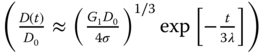 [45] during dripping using a Photron camera (Photron Fastcam MC2.1, Photron, San Diego, CA), where D(t) is the ligament diameter, D0 is the initial ligament diameter, and G1 is related to the elastic modulus. Then, the longest relaxation time was found based on the slope
 ![]() of the log–log plot of (D(t), t) during the pinch-off period. A power-law relaxation time model (
of the log–log plot of (D(t), t) during the pinch-off period. A power-law relaxation time model (![]() ), determined based on the measurements of 0.5%–2.0% alginate solutions, was used to estimate the longest relaxation time of alginate solutions with concentrations of 4%, 6%, and 8%, where c is the alginate concentration and c* is the critical coil overlap concentration. In addition, the specific viscosities as a function of alginate concentration were measured for alginate solutions with a concentration range of 0.01%–8.00%. Then other key viscoelastic properties of alginate solutions, including the intrinsic viscosity ([η]) [46], the critical coil overlap concentration (c*), and the entanglement concentration (ce), were determined as 220 ml/g, 0.32%, and 1.20%, respectively. Therefore, 2%, 4%, 6%, and 8% alginate solutions herein are considered semi-dilute entangled solutions. As shown in Table 9.3, two laser printing experiments have been conducted to appreciate the effects of laser fluence and alginate concentration on the jetting dynamics, respectively.
), determined based on the measurements of 0.5%–2.0% alginate solutions, was used to estimate the longest relaxation time of alginate solutions with concentrations of 4%, 6%, and 8%, where c is the alginate concentration and c* is the critical coil overlap concentration. In addition, the specific viscosities as a function of alginate concentration were measured for alginate solutions with a concentration range of 0.01%–8.00%. Then other key viscoelastic properties of alginate solutions, including the intrinsic viscosity ([η]) [46], the critical coil overlap concentration (c*), and the entanglement concentration (ce), were determined as 220 ml/g, 0.32%, and 1.20%, respectively. Therefore, 2%, 4%, 6%, and 8% alginate solutions herein are considered semi-dilute entangled solutions. As shown in Table 9.3, two laser printing experiments have been conducted to appreciate the effects of laser fluence and alginate concentration on the jetting dynamics, respectively.
Table 9.2 Material properties and key nondimensional numbers of sodium alginate solutions
| Sodium alginate concentration (w/v) | Density ρ (g/cm3) | Viscosity |
Surface tension γ (mN/m) | Relaxation time (µs) | Oh | Ec |
| 2% | 1.020 | 139.5 | 44.6 | 1650 | 2.38 | 7.06 |
| 4% | 1.040 | 855.8 | 44.5 | 10 462 | 15.04 | 7.01 |
| 6% | 1.060 | 3 123.6 | 43.6 | 34 358 | 53.05 | 6.39 |
| 8% | 1.080 | 8 278.9 | 42.7 | 80 893 | 140.76 | 5.56 |
Table 9.3 Design of experiments
| Experiment no. | Alginate concentration (w/v) | Laser fluence (mJ/cm2) |
| 1 | 2% | 500, 700, 900, 1100, 1300, and 1500 |
| 4% | 900, 1100, 1300, 1500, 1700, and 1900 | |
| 6% | 1100, 1300, 1500, 1700, 1900, 2100, and 2300 | |
| 8% | 1300, 1500, 1700, 1900, 2100, 2300, 2500, 2700, and 2900 | |
| 2 | 2%, 4%, 6%, and 8% | 1100 |
9.3.2.2 Typical Jetting Regimes
Figure 9.7a illustrates a representative jet/droplet formation process observed at 130 µs during printing of a 4% alginate solution under a 1300 mJ/cm2 laser fluence. Once a jet is formed, a primary droplet starts forming progressively at the head of the jet. Some key morphological features of the forming jet and droplet such as the ligament are depicted in Figure 9.7a. The jet velocity U herein was calculated by a linear fit of the jet head distance dependence on the measurement time [47]. The outmost droplet of the ligament is called primary droplet. Once the jet detaches from the quartz support, the trailing fluid behind the primary droplet is called tail. The breakup time represents the time of the first breakup taking place inside the field of view of the imaging system, and the breakup length means the ligament length measured when the first breakup is observed.
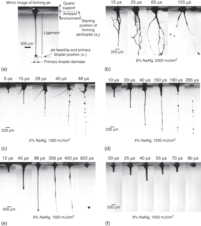
Figure 9.7 (a) Morphological features of a forming jet at 130 µs during printing 4% sodium alginate solution under a 1300 mJ/cm2 laser fluence and representative images of the jet regimes: (b) pluming/splashing (6% alginate, 2300 mJ/cm2), (c) jetting with a bulgy shape (2% alginate, 1300 mJ/cm2), (d) well-defined jetting with an initial bulgy shape (4% alginate, 1500 mJ/cm2), (e) well-defined jetting (6% alginate, 1500 mJ/cm2), and (f) no material transfer (8% alginate, 1300 mJ/cm2).
(Zhang et al. 2015 [29]. Reproduced with permission of American Chemical Society.)
The jetting morphology and breakup mechanism during laser printing were investigated using time-resolved imaging. As shown in Figure 9.7, five different jetting regimes are observed during the laser printing of different alginate solutions under different laser fluences: pluming/splashing (Figure 9.7b), jetting with a bulgy shape (Figure 9.7c), well-defined jetting with an initial bulgy shape (Figure 9.7d), well-defined jetting (Figure 9.7e), and no material transfer (Figure 9.7f). Well-defined jetting with an initial bulgy shape is a special jetting scenario during viscoelastic fluid printing, meaning that a jet with an initial bulgy shape may develop into a well-defined jet during the later jetting stage. Only well-defined jetting with or without an initial bulgy shape is considered as desirable and evaluated in this study.
In order to further illustrate the morphological evolution of forming jets under different alginate concentrations and laser fluences, the jet head and primary droplet position within the field of view as well as the jetting regime type are presented as a function of laser fluence (Figure 9.8a with a 2% alginate solution) and alginate concentration (Figure 9.8b with a 1300 mJ/cm2 laser fluence). Error bars in this study represent the plus or minus one-sigma variation. Some jetting images are presented to illustrate the jet morphology at some critical moments as indicated with the solid circles. It can be seen that the jet head and primary droplet position increases with the laser fluence, meaning a longer ligament length and a higher velocity under higher laser fluences if a jet can be formed. The jet head and primary droplet position decreases with the alginate concentration. This indicates that printing of higher concentration alginate solutions results in shorter ligament lengths and lower velocities. The jetting regime changes from no material transferred to well-defined jetting to well-defined jetting with an initial bulgy shape to jetting with a bulgy shape to pluming/splashing as the laser fluence increases or the alginate concentration decreases.
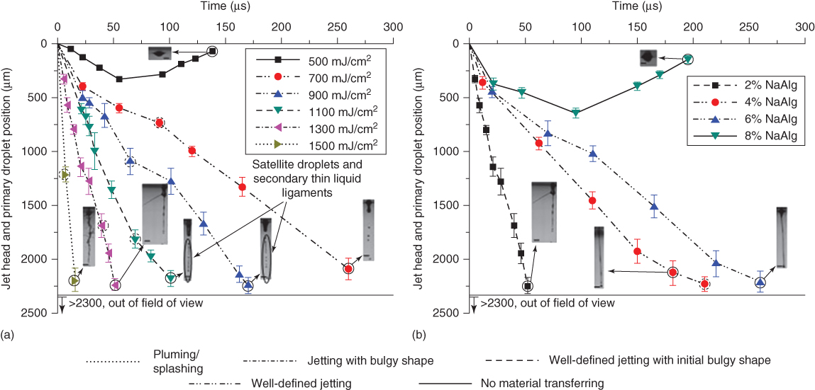
Figure 9.8 Jet/droplet morphological evolution under a) different laser fluences when printing a 2% alginate solution and b) different alginate concentrations when using a 1300 mJ/cm2 laser fluence. (The scale bar is 400 µm, and the dashed circle indicates the jet breakup moment as observed.)
(Zhang et al. 2015 [29]. Reproduced with permission of American Chemical Society.)
9.3.2.3 General Observation of the Jetting Dynamics
During laser printing of viscoelastic alginate solutions, most of the input laser energy is consumed for bubble expansion, eventually converting it into the viscous dissipation, elastic, surface, and kinetic energies of forming jets/droplets in this study. Once a jet is formed, it may break up differently due to the combined effects of liquid inertial, elastic, viscous, capillary, and ambient aerodynamic (gas inertia) forces acting on the jet. As the jet velocity increases, a jet may experience four different breakup mechanisms: Rayleigh breakup, first wind-induced breakup, second wind-induced breakup, and atomization mechanisms. Most liquid jet breakup can be attributed to the Rayleigh or Plateau–Rayleigh instability, a common mechanism during the breakup of cylindrical jets. Since the droplet formation process is not easily controllable under the second wind-induced and atomization mechanisms, they are not of interest during laser printing. Only the Rayleigh and first wind-induced breakups are expected for good droplet formation for laser printing.
For Rayleigh breakup, the inertio-capillary force is mainly responsible for the growth of perturbation, leading to pinch-off, and the aerodynamic force induced due to the relative motion between the liquid jet and ambient gas is negligible. When the aerodynamic force is large enough as the jet velocity increases, the growth rate of perturbation is enhanced via the aerodynamic force, and a higher growth rate leads to a faster breakup process and shorter breakup length [48, 49], indicating the first wind-induced breakup mechanism. The aerodynamic effect due to the surrounding gas is comparable to and can be as high as 10% [50] of the surface tension force. When the jet velocity further increases, a jet may experience the second wind-induced breakup and atomization mechanisms during which the growth of the perturbation is dominated by the aerodynamic force, and the most unstable perturbations turn out to be those with shorter wavelengths than those during Rayleigh breakup and first wind-induced breakup. The resulting drop size is much smaller than the jet diameter under the second wind-induced and atomization mechanisms [50, 51].
9.3.2.4 Effects of Laser Fluence on Jetting Dynamics
As seen from Figure 9.9a, the jet velocity of well-defined jets increases monotonically with the applied laser fluence for all the alginate solutions investigated since higher laser fluences introduce more energy into the system, resulting in a higher jet velocity. Similar observations were reported when laser printing alginate solutions [18] as well as Newtonian fluids and Newtonian fluid-based suspensions such as silver-nanoparticle-loaded ethylene glycol, glycerol, and ethanol suspensions [47] and glycerol solutions [31]. It can also be seen from Figure 9.9a that the velocity change of any alginate solution is more sensitive to the laser fluence under higher laser fluences, demonstrating a shear-thinning behavior. This is different from that observed during the laser printing of Newtonian fluids and suspensions such as glycerol solutions [31] and glycerol-based suspensions [47], where the jet velocity increases nearly linearly with the laser fluence.
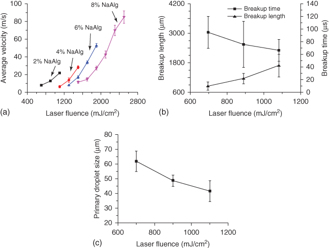
Figure 9.9 (a) Jet velocity of different alginate solutions, (b) breakup time and breakup length (2% alginate), and (c) primary droplet size (2% alginate) as a function of laser fluence.
(Zhang et al. 2015 [29]. Reproduced with permission of American Chemical Society.)
As observed from Figure 9.9a, the achievable velocity for well-defined jetting increases with the alginate concentration. For viscoelastic fluids, the storage modulus measures their stored energy, representing the elastic effect, while the loss modulus measures the energy dissipated as heat, representing the viscous effect. For alginate solutions [52], the storage and loss moduli increase with the alginate concentration, indicating the increase of elastic and viscous effects. As the concentration increases, the elastic and viscous effects increase while the surface tension decreases, which delays the perturbation growth on forming jets. As such, it suppresses jetting with a bulgy shape and splashing/pluming. Furthermore, as the jet velocity increases, the increased aerodynamic force induced by the faster relative motion between the fluid jet and the ambient gas is better balanced through the increased viscous and elastic forces of high-concentration alginate solutions. Thus, higher concentration alginate solutions can achieve a higher velocity while maintaining a well-defined jet.
Only the 2% alginate solution-related breakup observations are reported here since jets of other solutions except the breakup of 4% alginate solutions under 1100 mJ/cm2 do not break up within the field of view. For the 2% alginate solution, the breakup time, as seen from Figure 9.9b, shows a decreasing tendency with the applied laser fluence, which is comparable with the observation during the laser printing of silver-nanoparticle-loaded Newtonian fluid-based suspensions [47]. At higher laser fluences, the jet velocity is higher, which may lead to a more elongated and narrower jet [53]. As such, the required breakup time may be shorter to break up a narrower jet as observed in this study. In addition, Figure 9.9b shows that the breakup length increases with the laser fluence, which is consistent with the breakup length observation during the nozzle jetting of viscoelastic polyethylene oxide (PEO) solutions [54].
It is found from Figure 9.9c that the primary droplet size decreases when the laser fluence increases. Narrower jets under higher laser fluences lead to the formation of smaller primary droplets. After primary droplets detach from the ligaments, growing perturbations further break up the flying ligaments into multiple satellite droplets and/or secondary liquid ligaments due to the Plateau–Rayleigh instabilities as shown in Figure 9.9a. It is noted that the droplet size after deposition [12] is different from the size of primary droplets, which may contribute together with other possible satellite droplets to the size of deposited droplets. Generally speaking, such satellite droplets, if they do not finally merge with their primary droplet, should be avoided during printing.
9.3.2.5 Effects of Alginate Concentration on Jetting Dynamics
Since the effects of alginate concentration on the jetting dynamics are only examined based on well-defined jets with their breakups observed within the field of view, only a few observations are presented here. It can be seen from Figure 9.10a that the jet velocity decreases as the alginate concentration increases. As aforementioned, both the elastic and viscous effects increase with the alginate concentration. When the concentration increases, the viscous dissipation during jetting increases, and the elastic energy stored in a jet also increases. As a result, the remaining jet kinetic energy decreases accordingly, resulting in a lower jet velocity. Such a trend is consistent with the observations during the laser printing of alginate solutions with different concentrations [55].

Figure 9.10 (a) Jet velocity as a function of alginate concentration, (b) breakup time and breakup length, and (c) size of the primary droplet size under a 1100 mJ/cm2 laser fluence.
(Zhang et al. 2015 [29]. Reproduced with permission of American Chemical Society.)
The effects of alginate concentration on the breakup time, breakup length, and primary droplet size are studied in terms of jets of 2% and 4% alginate solutions under a 1100 mJ/cm2 laser fluence. As shown in Figure 9.10b, the breakup time increases while the breakup length decreases with the concentration. The increased viscous and elastic effects of higher concentration solutions resist the capillary effect and delay the breakup, leading to an increased breakup time [56]. This conclusion is in good agreement with the reported observations during the inkjet printing of cell-laden alginate solutions [57] and cellulose ester polymer solutions [58].
Coil overlap concentration represents the degree of entanglement among ploymer chains and is usually used to distiguish semi-dilute from dilute polymer solutions. For a solution with a concentration higher than its critical coil overlap concentration, it is reported that the ligament length at breakup decreases with the concentration during the inkjet printing of viscoelastic cellulose ester solutions [58]. Since 2% or higher concentrations of alginate solutions are higher than their coil overlap concentration as aforementioned, the higher the alginate concentration, the shorter the breakup length.
For 2% alginate solution jets, the primary droplet detaches from the jet head as a type of front pinching, and most material is still kept inside the ligament. For 4% alginate solution jets, the ligament thinning process is delayed by the increased viscoelastic effect of higher concentration alginate solutions. The pinch-off mechanism is a type of middle pinching and different from that during 2% alginate printing as seen from Figure 9.11. As a result, the breakup length is shorter, and the primary droplet is larger.

Figure 9.11 Different pinch-off locations for (a) 2% and (b) 4% alginate solutions.
(Zhang et al. 2015 [29]. Reproduced with permission of American Chemical Society.)
9.3.2.6 Jettability Phase Diagram
As observed, there is a specific laser fluence and/or alginate concentration range for the formation of desirable jetting. The jettability of Newtonian fluids has been evaluated using a nondimensional number J, the inverse of the Ohnesorge number (![]() ), as discussed in Section 9.3.2.4, and the proposed J number, laser fluence, and glycerol concentration help distinguish different jet-forming regimes during the laser printing of Newtonian glycerol–water solutions [31]. Unfortunately, no dimensionless number-based jettability diagrams were proposed [31]. In addition, the alginate solution in this study, as a typical viscoelastic fluid, behaves significantly different during laser printing due to its elasticity and cannot be characterized by the proposed J number only. Polymer stretching-induced elastic effect affects jetting and delays the jet breakup time, so the elastic effect should be incorporated in jettability phase diagrams for the evaluation of alginate laser printing. Therefore, an additional elasticity-related nondimensional number, Ec or De, is required for the characterization of the jetting dynamics during laser printing of viscoelastic fluids [29]. Ideally, nondimensional number-based jettability diagrams, which represent various operating conditions and materials properties, are expected to fully capture the jetting dynamics during alginate laser printing. For the 2–8% sodium alginate solutions studied herein, Oh > 1, indicating that the thinning and breakup process is dominated by the viscous force. As such, the jet/droplet formation process should be better described by the Oh and Ec numbers. In addition, the Weber number
), as discussed in Section 9.3.2.4, and the proposed J number, laser fluence, and glycerol concentration help distinguish different jet-forming regimes during the laser printing of Newtonian glycerol–water solutions [31]. Unfortunately, no dimensionless number-based jettability diagrams were proposed [31]. In addition, the alginate solution in this study, as a typical viscoelastic fluid, behaves significantly different during laser printing due to its elasticity and cannot be characterized by the proposed J number only. Polymer stretching-induced elastic effect affects jetting and delays the jet breakup time, so the elastic effect should be incorporated in jettability phase diagrams for the evaluation of alginate laser printing. Therefore, an additional elasticity-related nondimensional number, Ec or De, is required for the characterization of the jetting dynamics during laser printing of viscoelastic fluids [29]. Ideally, nondimensional number-based jettability diagrams, which represent various operating conditions and materials properties, are expected to fully capture the jetting dynamics during alginate laser printing. For the 2–8% sodium alginate solutions studied herein, Oh > 1, indicating that the thinning and breakup process is dominated by the viscous force. As such, the jet/droplet formation process should be better described by the Oh and Ec numbers. In addition, the Weber number ![]() , which represents inertial to capillary effects, is introduced as a process-dynamics-related dimensionless number to appreciate the jetting dynamics.
, which represents inertial to capillary effects, is introduced as a process-dynamics-related dimensionless number to appreciate the jetting dynamics.
In order to illustrate the dependence of jetting regimes on the dimensionless numbers, the jetting regimes are mapped out in a 3D phase diagram in a (We, Ec, Oh) space as shown in Figure 9.12a by considering the contributions from both the process dynamics (We) and the material properties (Ec and Oh). As shown in Table 9.1, as the alginate concentration increases from 2% to 8%, the Oh number increases from 2.38 to 140.76 and the Ec number decreases from 7.06 to 5.56. Higher concentration alginate solutions, meaning more pronounced viscous and elastic effects, help suppress the growth of perturbations and produce well-defined jets, if formed.
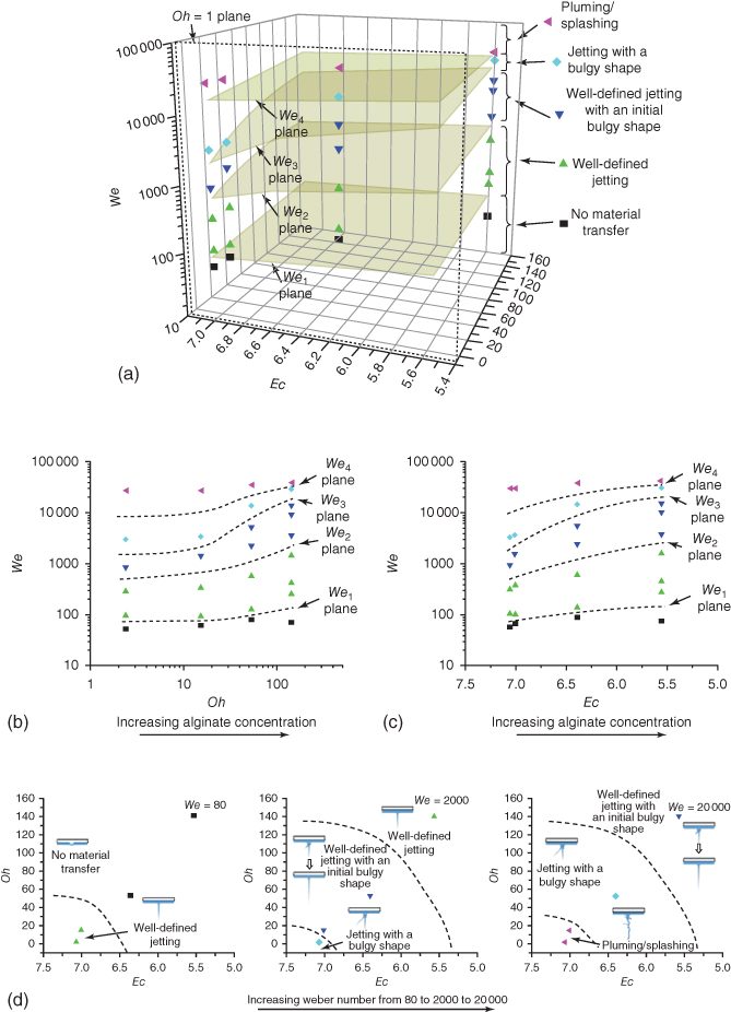
Figure 9.12 Jetting regime as a function of (a) We, Oh, and Ec numbers, (b) We and Oh numbers, (c) We and Ec numbers, and (d) Oh and Ec numbers.
(Zhang et al. 2015 [29]. Reproduced with permission of American Chemical Society.)
For further illustration, four We number-defined planes in (We, Oh) and (We, Ec) spaces are drawn as mid-planes to distinguish two nearby jetting regimes as seen in Figure 9.12b,c. Herein the We number is determined based on velocity measurements, which is convenient for understanding the underlying physics. However, such velocity information should be predicted first for process planning. These two phase diagrams show five distinct jet formation regimes in both the (We, Oh) and (We, Ec) spaces. Similarly, it is noted that the We and Oh numbers were also selected to construct the dripping/jetting [59] and satellite droplet formation [49] phase diagrams. As the We number increases, the jetting behavior changes from no material transfer to well-defined jetting to well-defined jetting with an initial bulgy shape to jetting with a bulgy shape to pluming/splashing for both phase diagrams. As the Oh number increases or the Ec number decreases, which represents an increasing alginate concentration, the We number required for the jetting regime switch increases accordingly. For a given We number, increasing viscous and/or elastic effects help stabilize jetting or even suppress the formation of jets as seen from Figure 9.12d, which illustrates the effect of material properties in a (Oh, Ec) space. A similar material property-based Oh and De (with applicable characteristic process times to be De0 and Ec) space was also proposed to study the beads-on-a-string phenomenon during viscoelastic liquid bridge breakup [60].
It should be noted that the change of the Ec number of different alginate solutions is not only different (decreasing) but also relatively small when compared with the change of the Oh number, and this is determined by the alginate rheological properties as measured. For reference, the Reynolds numbers (![]() ) of different solutions may change from smaller than 1 to larger than 1 when the laser fluence increases. For example, the Reynolds numbers change from 0.5 to 10.9 when the laser fluence increases during printing the 4% alginate solution, indicating an increasing significance of inertial over viscous forces.
) of different solutions may change from smaller than 1 to larger than 1 when the laser fluence increases. For example, the Reynolds numbers change from 0.5 to 10.9 when the laser fluence increases during printing the 4% alginate solution, indicating an increasing significance of inertial over viscous forces.
9.4 Laser Printing Applications Using Optimized Printing Conditions
To demonstrate the potential of laser printing as an effective technique for the printing of soft materials, the resulting knowledge from the jetting dynamics study is further applied to the freeform fabrication of 3D Y-shaped tubes using two different bioinks: 8% alginate solution and 2% alginate-based suspension of mouse fibroblasts (NIH 3T3, ATCC, Rockville, MD). Laser printing of cells for tissue engineering has been discussed in detail in Chapter 15. Herein, Y-shaped tubes without and with cells have been printed since such tubes are the basic constituent of vascular structures [61]. Vascularization is often correctly identified as a main technological barrier for building 3D human organs [62]. Without adequate vascularization, tissue-engineered constructs and organs could not survive and undergo intensive apoptosis and necrosis, and the capability to print Y-shaped tubes is not only an enabling step but also a critical indicator of the overall feasibility of organ printing.
The detailed procedure for the fabrication of 3D Y-shaped tubes has been outlined by Xiong et al. [63]. Calcium-chloride-based solution was used to gel the deposited droplet during the laser printing of Y-shaped tubes. It is assumed that the gelation does not significantly change the printing quality, which was confirmed in the results as well. During 3D laser bioprinting, each structure/construct is printed in a layer-by-layer manner, and each layer is a continuous feature made from numerous printed droplets on a receiving substrate. In order to print 2D features for each layer, the receiving substrate needs to be moved laterally to control the position of the printed droplets. Once a layer is finished, the receiving substrate moves vertically accordingly to cooperate with the thickness of each deposited layer. For better construct printing quality, printing conditions were identified based on the approach proposed in a previous line-printing study [28]. Specifically, the optimal printing conditions considering the substrate velocity have been identified as 2125 mJ/cm2 laser fluence (actual laser fluence as estimated after transmitting through the quartz support), 100 mm/min substrate velocity, and 10 Hz laser pulse repetition rate for the 8% alginate solution [28]. Similarly, for cellular bioinks with a cell concentration of 5 × 10⁶ cells/ml and 2% (w/v) alginate, 1445 mJ/cm2 laser fluence (actual laser fluence as estimated after transmitting through the quartz support), 80 mm/min substrate velocity, and 10 Hz repetition rate are identified as optimal based on the resulting printing quality.
To vertically print Y-shaped constructs, which have a straight segment and two inclined overhang segments as shown in Figure 9.13a, consideration should be paid to overhang structures, which include a spanning feature at the saddle location. Since solid support requires additional work of postprocessing, the calcium chloride solution was used as a dual-purpose liquid support and cross-linking solution [64]. Besides gelling deposited materials, the cross-linking solution (calcium chloride solution herein) also serves as a support material by providing a buoyant force as shown in the inset of Figure 9.13a. When compared with the gravitational force, the buoyant force provided by the calcium chloride solution is significant and acts as an effective support together with the adhesive force from previously deposited gel materials to hold printed structures [64]. Therefore, the printing of overhang parts of Y-shaped tubes is permissible by printing layers slightly overhanging away from a previously printed layer. Figure 9.13b shows a representative Y-shaped alginate tubular construct with an inclination angle of 45° and a diameter of 5 mm. The Y-shaped tube has an average wall thickness of 1.4 ± 0.3 mm as measured based on the bottom straight portion and a total height of around 9.5 mm. With the help of supporting force provided by the calcium chloride solution, the two branch tubes are successfully fabricated and have an inclination angle of 45° approximately as designed. Figure 9.13c illustrates a printed Y-shaped cellular tube with a diameter of 5 mm, a total height of around 9.5 mm, and a wall thickness of 2.5 ± 0.3 mm. It has a well-defined morphology, while the wall thickness of Y-shaped cellular constructs is almost doubled by comparing it with that of alginate only tubes. This is attributed to the possible nonideal droplet formation process during the printing of bioinks containing cells.
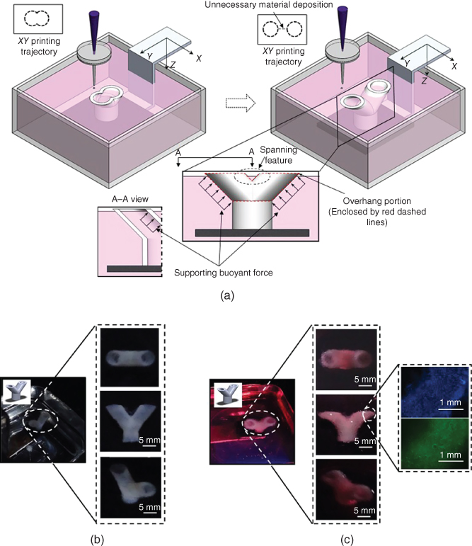
Figure 9.13 (a) Schematics of bifurcated construct printing (inset: a typical Y-shaped bifurcated structure), (b) representative images of Y-shaped alginate tubes printed using 8% sodium alginate solution (inset: different views of a printed Y-shaped alginate tube), and (c) Y-shaped cellular tubes printed with 2% alginate and 5 × 10⁶ cells/ml bioink (left inset: different views of a printed Y-shaped cellular tube, and right inset: printed cells dyed in blue and living cells dyed in green).
(Xiong et al. 2015 [63]. Reproduced with permission of Institute of Physics.)
Furthermore, several layers of printed cellular tubes were dissected and dyed to observe the printed cells. The right inset of Figure 9.13c shows all deposited cells in blue, which were dyed using Hoechst 33342 (Molecular Probes, Eugene, OR), and living cells in green, which were dyed using fluorescein diacetate (FDA) (Molecular Probes, Eugene, OR). Considering the control effect, the postprinting cell viability of printed constructs is 68.1% immediately after printing and 70.8% after 24 h of incubation. The cell viability is reasonable for effective bioprinting, and the observed increase of cell viability after incubation is attributed to the possible cell injury recovery and regular cell proliferation.
9.5 Conclusions and Future Work
This chapter has reviewed the effects of fluid properties as well as the combined effects of laser fluence and fluid properties on the jet formation process during laser printing of representative Newtonian glycerol and viscoelastic alginate solutions, respectively. A time-resolved imaging analysis-based approach has been implemented to investigate the jet formation process. The knowledge obtained from the jetting dynamics study has been further applied to investigate the feasibility of 3D alginate and cellular tubes using laser printing.
During the laser printing of Newtonian glycerol solutions, it is found that the jetting dynamics is a function of fluid properties such as the glycerol concentration and operating conditions such as the laser fluence. If the laser fluence is too low and/or the glycerol concentration is too high, it is less likely for a bubble to lead to liquid ejection during its expansion/collapse cycle. There is not enough kinetic energy provided by the expanding bubble. Even when a jet can be formed, it retracts back after the bubble collapses. If the laser fluence is too high and/or the glycerol concentration is too low, it is also difficult to form a well-developed jet since dramatic bubble expansion may lead to a bulgy shape and even splashing. Only under some selected conditions of glycerol concentration and laser fluence, can a well-defined jet form. When a jetting fluid is given, its jettability (J) can be characterized as the inverse of Ohnesorge number. It is observed that a good jet forms at 0.09 ≤ J ≤ 1.76 in this study under the laser fluence of 717 mJ/cm2.
During the laser printing of viscoelastic alginate solutions, five jetting regimes are identified as follows: no material transfer, well-defined jetting, well-defined jetting with an initial bulgy shape, jetting with a bulgy shape, and pluming/splashing. Among them, well-defined jetting with and without an initial bulgy shape are the desirable jetting regimes. It is found that the jetting behavior changes from no material transfer to well-defined jetting to well-defined jetting with an initial bulgy shape to jetting with a bulgy shape to pluming/splashing when the laser fluence increases. When the alginate concentration increases, the jetting dynamics changes in an inverse order as the laser fluence increases. In particular, for the desirable well-defined jetting regimes, as the laser fluence increases, the jet velocity and breakup length increase while the breakup time and primary droplet size decrease; as the alginate concentration increases, the jet velocity and breakup length decrease while the breakup time and primary droplet size increase. Furthermore, Ohnesorge, elasto-capillary, and Weber number-based phase diagrams are presented to better appreciate the dependence of jetting regimes on the laser fluence and alginate concentration. Four Weber number-defined planes can be used to distinguish different jetting regimes. The increase of viscous and elastic effects helps stabilize the jetting process or even suppress the formation of jets.
Y-shaped tubes based on the knowledge obtained from the jetting dynamics study have been printed using two different bioinks: 8% alginate solution and 2% alginate-based mouse fibroblast suspension. It has been demonstrated that 3D cellular constructs with bifurcated overhang structures can be adequately fabricated under optimal printing conditions using laser printing. The printing of overhang and spanning structures can be achieved using a dual-purpose crosslinking solution, which functions as a support material. The postprinting cell viability measurements immediately after printing as well as after 24-h incubation are above 60% for printed Y-shaped fibroblast tubes.
Acknowledgments
The study was partially supported by the National Science Foundation (CMMI 1314830). The authors would like to acknowledge the contribution from and discussion with D. Chrisey, D. Corr, J. Yan., C. Xu, and Y. Lin over the years.
References
- 1 Piqué, A., Chrisey, D.B., Auyeung, R.C.Y., Fitz-Gerald, J., Wu, H.D., McGill, R.A., Lakeou, S., Wu, P.K., Nguyen, V., and Duignan, M. (1999) A novel laser transfer process for direct writing of electronic and sensor materials. Appl. Phys. A, 69 (1), S279–S284.
- 2 Ringeisen, B.R., Othon, C.M., Barron, J.A., Young, D., and Spargo, B.J. (2006) Jet-based methods to print living cells. Biotechnol. J., 1 (9), 930–948.
- 3 Lin, Y., Huang, G., Huang, Y., Jeremy Tzeng, T.R., and Chrisey, D. (2010) Effect of laser fluence in laser-assisted direct writing of human colon cancer cell. Rapid Prototyp. J., 16 (3), 202–208.
- 4 Schiele, N.R., Corr, D.T., Huang, Y., Raof, N.A., Xie, Y., and Chrisey, D.B. (2010) Laser-based direct-write techniques for cell printing. Biofabrication, 2 (3), 032001.
- 5 Lin, Y., Huang, Y., and Chrisey, D.B. (2011) Metallic foil-assisted laser cell printing. J. Biomech. Eng., 133 (2), 025001.
- 6 Lin, Y. and Huang, Y. (2011) Laser-assisted fabrication of highly viscous alginate microsphere. J. Appl. Phys., 109 (8), 083107.
- 7 Guillotin, B., Souquet, A., Catros, S., Duocastella, M., Pippenger, B., Bellance, S., Bareille, R., Rémy, M., Bordenave, L., Amédée, J., and Guillemot, F. (2010) Laser assisted bioprinting of engineered tissue with high cell density and microscale organization. Biomaterials, 31 (28), 7250–7256.
- 8 Gruene, M., Pflaum, M., Hess, C., Diamantouros, S., Schlie, S., Deiwick, A., Koch, L., Wilhelmi, M., Jockenhoevel, S., Haverich, A., and Chichkov, B. (2011) Laser printing of three-dimensional multicellular arrays for studies of cell–cell and cell–environment interactions. Tissue Eng. Part C, 17 (10), 973–982.
- 9 Ringeisen, B.R., Pirlo, R.K., Wu, P.K., Boland, T., Huang, Y., Sun, W., Hamid, Q., and Chrisey, D.B. (2013) Cell and organ printing turns 15: diverse research to commercial transitions. MRS Bull., 38 (10), 834–843.
- 10 Riggs, B.C., Dias, A.D., Schiele, N.R., Cristescu, R., Huang, Y., Corr, D.T., and Chrisey, D.B. (2011) Matrix-assisted pulsed laser methods for biofabrication. MRS Bull., 36 (12), 1043–1050.
- 11 Yan, J., Huang, Y., and Chrisey, D.B. (2013) Laser-assisted printing of alginate long tubes and annular constructs. Biofabrication, 5 (1), 015002.
- 12 Lin, Y., Huang, Y., and Chrisey, D.B. (2009) Droplet formation in matrix-assisted pulsed-laser evaporation direct writing of glycerol-water solution. J. Appl. Phys., 105 (9), 093111.
- 13 Colina, M., Duocastella, M., Fernández-Pradas, J.M., Serra, P., and Morenza, J.L. (2006) Laser-induced forward transfer of liquids: study of the droplet ejection process. J. Appl. Phys., 99 (8), 084909.
- 14 Duocastella, M., Kim, H., Serra, P., and Piqué, A. (2012) Optimization of laser printing of nanoparticle suspensions for microelectronic applications. Appl. Phys. A, 106 (3), 471–478.
- 15 Serra, P., Duocastella, M., Fernández-Pradas, J.M., and Morenza, J.L. (2009) Liquids microprinting through laser-induced forward transfer. Appl. Surf. Sci., 255 (10), 5342–5345.
- 16 Duocastella, M., Fernández-Pradas, J.M., Morenza, J.L., and Serra, P. (2009) Time-resolved imaging of the laser forward transfer of liquids. J. Appl. Phys., 106 (8), 084907.
- 17 Duocastella, M., Fernández-Pradas, J.M., Morenza, J.L., and Serra, P. (2010) Sessile droplet formation in the laser-induced forward transfer of liquids: a time-resolved imaging study. Thin Solid Films, 518 (18), 5321–5325.
- 18 Unger, C., Gruene, M., Koch, L., Koch, J., and Chichkov, B.N. (2011) Time-resolved imaging of hydrogel printing via laser-induced forward transfer. Appl. Phys. A, 103 (2), 271–277.
- 19 Young, D., Auyeung, R.C.Y., Piqué, A., Chrisey, D.B., and Dlott, D.D. (2002) Plume and jetting regimes in a laser based forward transfer process as observed by time-resolved optical microscopy. Appl. Surf. Sci., 197, 181–187.
- 20 Guillemot, F., Souquet, A., Catros, S., Guillotin, B., Lopez, J., Faucon, M., Pippenger, B., Bareille, R., Rémy, M., Bellance, S., and Chabassier, P. (2010) High-throughput laser printing of cells and biomaterials for tissue engineering. Acta Biomater., 6 (7), 2494–2500.
- 21 Brown, M.S., Kattamis, N.T., and Arnold, C.B. (2010) Time-resolved study of polyimide absorption layers for blister-actuated laser-induced forward transfer. J. Appl. Phys., 107 (8), 083103.
- 22 Brown, M.S., Kattamis, N.T., and Arnold, C.B. (2011) Time-resolved dynamics of laser-induced micro-jets from thin liquid films. Microfluid. Nanofluid., 11 (2), 199–207.
- 23 Duocastella, M., Patrascioiu, A., Dinca, V., Fernández-Pradas, J.M., Morenza, J.L., and Serra, P. (2011) Study of liquid deposition during laser printing of liquids. Appl. Surf. Sci., 257 (12), 5255–5258.
- 24 Duocastella, M., Colina, M., Fernández-Pradas, J.M., Serra, P., and Morenza, J.L. (2007) Study of the laser-induced forward transfer of liquids for laser bioprinting. Appl. Surf. Sci., 253 (19), 7855–7859.
- 25 Wu, P.K. and Ringeisen, B.R. (2010) Development of human umbilical vein endothelial cell (HUVEC) and human umbilical vein smooth muscle cell (HUVSMC) branch/stem structures on hydrogel layers via biological laser printing (BioLP). Biofabrication, 2 (1), 014111.
- 26 Gaebel, R., Ma, N., Liu, J., Guan, J., Koch, L., Klopsch, C., Gruene, M., Toelk, A., Wang, W., Mark, P., and Wang, F. (2011) Patterning human stem cells and endothelial cells with laser printing for cardiac regeneration. Biomaterials, 32 (35), 9218–9230.
- 27 Koch, L., Deiwick, A., Schlie, S., Michael, S., Gruene, M., Coger, V., Zychlinski, D., Schambach, A., Reimers, K., Vogt, P.M., and Chichkov, B. (2012) Skin tissue generation by laser cell printing. Biotechnol. Bioeng., 109 (7), 1855–1863.
- 28 Xiong, R., Zhang, Z., and Huang, Y. (2015) Identification of optimal printing conditions for laser printing of alginate tubular constructs. J. Manuf. Processes, 20, 450–455.
- 29 Zhang, Z., Xiong, R., Mei, R., Huang, Y., and Chrisey, D.B. (2015) Time-resolved imaging study of jetting dynamics during laser printing of viscoelastic alginate solutions. Langmuir, 31 (23), 6447–6456.
- 30 Wang, W., Li, G., and Huang, Y. (2009) Modeling of bubble expansion-induced cell mechanical profile in laser-assisted cell direct writing. J. Manuf. Sci. Eng., 131 (5), 051013.
- 31 Yan, J., Huang, Y., Xu, C., and Chrisey, D.B. (2012) Effects of fluid properties and laser fluence on jet formation during laser direct writing of glycerol solution. J. Appl. Phys., 112 (8), 083105.
- 32 Xiong, R., Zhang, Z., Shen, J., Lin, Y., Huang, Y., and Chrisey, D.B. (2015) Bubble formation modeling during laser direct writing of glycerol solutions. J. Micro Nano-Manuf., 3 (1), 011004.
- 33 Yoo, J.H., Borisov, O.V., Mao, X., and Russo, R.E. (2001) Existence of phase explosion during laser ablation and its effects on inductively coupled plasma-mass spectroscopy. Anal. Chem., 73 (10), 2288–2293.
- 34 Wang, W., Lin, Y., and Huang, Y. (2011) Modeling of thermoelastic stress wave in laser-assisted cell direct writing. J. Manuf. Sci. Eng., 133 (2), 024502.
- 35 Schaffer, C., Nishimura, N., Glezer, E., Kim, A., and Mazur, E. (2002) Dynamics of femtosecond laser-induced breakdown in water from femtoseconds to microseconds. Opt. Express, 10 (3), 196–203.
- 36 Brujan, E.A. and Vogel, A. (2006) Stress wave emission and cavitation bubble dynamics by nanosecond optical breakdown in a tissue phantom. J. Fluid Mech., 558, 281–308.
- 37 Lauterborn, W. and Ohl, C.D. (1997) Cavitation bubble dynamics. Ultrason. Sonochem., 4 (2), 65–75.
- 38 Brujan, E.A., Ikeda, T., and Matsumoto, Y. (2005) Jet formation and shock wave emission during collapse of ultrasound-induced cavitation bubbles and their role in the therapeutic applications of high-intensity focused ultrasound. Phys. Med. Biol., 50 (20), 4797–4810.
- 39 Kaur, K.S., Fardel, R., May-Smith, T.C., Nagel, M., Banks, D.P., Grivas, C., Lippert, T., and Eason, R.W. (2009) Shadowgraphic studies of triazene assisted laser-induced forward transfer of ceramic thin films. J. Appl. Phys., 105 (11), 113119.
- 40 Barron, J.A., Young, H.D., Dlott, D.D., Darfler, M.M., Krizman, D.B., and Ringeisen, B.R. (2005) Printing of protein microarrays via a capillary-free fluid jetting mechanism. Proteomics, 5 (16), 4138–4144.
- 41 Jang, D., Kim, D., and Moon, J. (2009) Influence of fluid physical properties on ink-jet printability. Langmuir, 25 (5), 2629–2635.
- 42 Herran, C.L. and Huang, Y. (2012) Alginate microsphere fabrication using bipolar wave-based drop-on-demand jetting. J. Manuf. Processes, 14 (2), 98–106.
- 43 Herran, C.L., Huang, Y., and Chai, W. (2012) Performance evaluation of bipolar and tripolar excitations during nozzle-jetting-based alginate microsphere fabrication. J. Micromech. Microeng., 22 (8), 085025.
- 44 McKinley, G.H. and Renardy, M. (2011) Wolfgang von ohnesorge. Phys. Fluids A, 23 (12), 127101.
- 45 Entov, V.M. and Hinch, E.J. (1997) Effect of a spectrum of relaxation times on the capillary thinning of a filament of elastic liquid. J. Non-Newtonian Fluid Mech., 72 (1), 31–53.
- 46 Wolf, B.A. (2007) Polyelectrolytes revisited: reliable determination of intrinsic viscosities. Macromol. Rapid Commun., 28 (2), 164–170.
- 47 Boutopoulos, C., Kalpyris, I., Serpetzoglou, E., and Zergioti, I. (2014) Laser-induced forward transfer of silver nanoparticle ink: time-resolved imaging of the jetting dynamics and correlation with the printing quality. Microfluid. Nanofluid., 16 (3), 493–500.
- 48 Gordillo, J.M. and Pérez-Saborid, M. (2005) Aerodynamic effects in the break-up of liquid jets: on the first wind-induced break-up regime. J. Fluid Mech., 541, 1–20.
- 49 van Hoeve, W., Gekle, S., Snoeijer, J.H., Versluis, M., Brenner, M.P., and Lohse, D. (2010) Breakup of diminutive Rayleigh jets. Phys. Fluids A, 22 (12), 122003.
- 50 Lin, S.P. and Reitz, R.D. (1998) Drop and spray formation from a liquid jet. Annu. Rev. Fluid Mech., 30 (1), 85–105.
- 51 Reitz, R.D. and Bracco, F.V. (1982) Mechanism of atomization of a liquid jet. Phys. Fluids A, 25 (10), 1730–1742.
- 52 Fu, S., Thacker, A., Sperger, D.M., Boni, R.L., Velankar, S., Munson, E.J., and Block, L.H. (2010) Rheological evaluation of inter-grade and inter-batch variability of sodium alginate. AAPS PharmSciTecn, 11 (4), 1662–1674.
- 53 Brown, M.S., Brasz, C.F., Ventikos, Y., and Arnold, C.B. (2012) Impulsively actuated jets from thin liquid films for high-resolution printing applications. J. Fluid Mech., 709, 341–370.
- 54 Mun, R.P., Byars, J.A., and Boger, D.V. (1998) The effects of polymer concentration and molecular weight on the breakup of laminar capillary jets. J. Non-Newtonian Fluid Mech., 74 (1), 285–297.
- 55 Gruene, M., Unger, C., Koch, L., Deiwick, A., and Chichkov, B. (2011) Dispensing pico to nanolitre of a natural hydrogel by laser-assisted bioprinting. Biomed. Eng. Online, 10 (1), 19.
- 56 McKinley, G.H. (2005) Visco-elasto-capillary thinning and break-up of complex fluids. Annu. Rheol. Rev., 1–48.
- 57 Xu, C., Zhang, M., Huang, Y., Ogale, A., Fu, J., and Markwald, R.R. (2014) Study of droplet formation process during drop-on-demand inkjetting of living cell-laden bioink. Langmuir, 30 (30), 9130–9138.
- 58 Xu, D., Sanchez-Romaguera, V., Barbosa, S., Travis, W., de Wit, J., Swan, P., and Yeates, S.G. (2007) Inkjet printing of polymer solutions and the role of chain entanglement. J. Mater. Chem., 17 (46), 4902–4907.
- 59 Ambravaneswaran, B., Subramani, H.J., Phillips, S.D., and Basaran, O.A. (2004) Dripping-jetting transitions in a dripping faucet. Phys. Rev. Lett., 93 (3), 034501.
- 60 Bhat, P.P., Appathurai, S., Harris, M.T., Pasquali, M., McKinley, G.H., and Basaran, O.A. (2010) Formation of beads-on-a-string structures during break-up of viscoelastic filaments. Nat. Phys., 6 (8), 625–631.
- 61 Lalan, S., Pomerantseva, I., and Vacanti, J.P. (2001) Tissue engineering and its potential impact on surgery. World J. Surg., 25 (11), 1458–1466.
- 62 Krogh, A. (1919) The number and distribution of capillaries in muscles with calculations of the oxygen pressure head necessary for supplying the tissue. J. Physiol., 52 (6), 409–415.
- 63 Xiong, R., Zhang, Z., Chai, W., Huang, Y., and Chrisey, D.B. (2015) Freeform drop-on-demand laser printing of 3D alginate and cellular constructs. Biofabrication, 7 (4), 045011.
- 64 Christensen, K., Xu, C., Chai, W., Zhang, Z., Fu, J., and Huang, Y. (2015) Freeform inkjet printing of cellular structures with bifurcations. Biotechnol. Bioeng., 112 (5), 1047–1055.