Chapter 14
Laser Printing of Proteins and Biomaterials
Alexandra Palla Papavlu, Valentina Dinca and Maria Dinescu
Lasers Department, National Institute for Lasers, Plasma, and Radiation Physics, Atomistilor 409, 077125 Magurele, Romania
14.1 Introduction
Today, a strong research effort is directed toward the development and integration of new materials, especially of polymers and biomolecules, which are essential in pharmaceutical, bioengineering, and sensing applications. In fact, patterning of organic and inorganic materials, in particular enabling precise positioning of different materials with nano- and microscale resolution over large areas, is the main demand in the development of next-generation sensors, biosensors, and microarray chip devices [1].
Biomicrodevices are miniaturized devices based on biologically derived components (e.g., DNA, proteins, and cells) combined or integrated with microfabricated substrates. The methods that had been originally developed for the microelectronics industry, such as photolithography, and for the fabrication of microelectromechanically systems, such as silicon micromachining, were the first to be adapted to the fabrication of biomicrodevices.
Research in this field started in the late 1970s and resulted in the development of the first miniaturized gas chromatography system on a silicon chip [2]. However, the last 10 years have witnessed a truly exponential growth in the research focused on the development of biomicrodevices. Today, this field of research represents one of the most important sectors of the biotechnology and biomedical industry, with applications ranging from drug discovery studies to tissue engineering. Research in this area has been motivated by the numerous advantages conferred by miniaturization, such as the reduction of device size, use of smaller volumes and consequent reduction of waste, high throughput, and batch processing [3, 4].
Before a biomicrodevice can be fully developed, many specific fabrication and biointeraction challenges must be addressed. Compared to silicon-based electronic devices, the challenges for the fabrication of biomicrodevices are much more diverse due to the large variety of biomaterials, fluids, and chemicals involved, as well as the spotting method. Among these challenges, we emphasize the spatial immobilization and bioactivity preservation of the selected biomolecules in the specific place on a surface. Different approaches regarding spotting/printing methods, printing media preparation, optimization of printing buffer for high binding efficiency of molecules to different microarray surfaces, and the evaluation of the produced microarrays performance must be considered.
Direct patterning methods have attracted an increasing attention in the last few years, in particular since their demonstrated ability to reach nanoscale patterning. The major concerns within this area of applications are related to protein malfunction after patterning, as proteins easily lose their activity due to various factors (denaturation, dehydration, or oxidation) [5]. Nowadays, simple methods such as dispensing or soaking techniques are used for depositing biological molecules in solution onto their binding or adsorbing substrates [6]. In addition, a multitude of contact and noncontact patterning methods have been developed for localized biomolecules patterning. For example, in contact methods, in order to generate high densities of biomolecule micropatterns on porous or solid materials, the factors to be considered include the nature of the liquid samples, the diameters of the pins or capillary dispensers, and the pin impact [7]. As miniaturization represents a requirement of biomicrodevice manufacturing, techniques such as dot blotting are unsuitable for depositions onto nonporous substrates as dots with diameters of/or larger than 1 mm are being produced with this technique [8]. Robotic microneedle array fabrication allows specific and localized antibody–antigen interactions as defined cognate spots in the array, with antibody–antigen pairs allowing detection of the cognate ligands at concentrations below 1 ng/ml [9]. Despite its ability to print hundreds of specific antibody or antigen solutions in an array, it is a time-consuming and costly technique with additional issues related to cross-contamination during tip cleaning [10]. Biocompatibility and the relatively expensive processing equipment are the main issues in the alternative photolithographic and/or microfluidic methods [11, 12].
Furthermore, microfluidic patterning is a versatile patterning technique that allows immobilizing multiple types of proteins on a variety of substrates [13]. The main limitation of this technique is the fabrication of an array where the same protein (or other analyte) is placed obligatory along one line. Microcontact printing (µCP) allows parallel and fast printing of bioreagents in hundreds of spots. µCP and, more recently, nCP offer a simple and convenient method to stamp a variety of “inks,” from proteins to peptides and other macromolecules. The method is parallel; however, as previously discussed, it can also be used to print different types of inks, even if this might require laborious alignment processes. The disadvantages of protein denaturation, contamination, and noncontrollability of the patterning process limit its use [14].
Spotting biological liquid samples onto different substrates may use also noncontact printing approaches such as the “inkjet” printing [15, 16]. Uniform patterning of different types of proteins using high-speed printing requires precise pressure control for each nozzle, preventing cross-contamination, and controlled but limited range of viscoelastic properties of the samples. In particular, the fast growing field of protein and cell microarrays demands for a fast and reliable noncontact printing technology. The multitude of printing samples often shows very different liquid properties, which highly influence the deposition behavior. In addition, the surface properties of microarray substrates vary in a wide range. As a result, different applications need specifically adopted printing systems, printing media, coupling chemistry of microarray slides, and surface properties. Thus, the production of custom microarrays requires a very flexible microarrayer technology.
In materials science, laser techniques revolutionized our understanding of materials by making it possible to design and integrate new materials with tailored properties for novel technology developments. The next step beyond conventional direct writing techniques, that is, inkjet printing, is the laser-induced forward transfer (LIFT) technique.
LIFT first appeared as a new deposition method for the direct writing of different dried inks to a glass substrate for the graphic industry [17–19]. At that point, it was called laser writing (LW) or material laser recording (MTR). In 1986, Bohandy et al. [20] deposited copper metal patterns onto fused-silica substrates under vacuum conditions by the same method and called it LIFT. Two years later, the same group demonstrated the same process under atmospheric conditions [21]. Detailed information on the origins of LIFT is given in Chapter 2.
In LIFT, a laser beam is focused through a transparent support plate onto a precursor thin film of the material to be transferred. Every single pulse promotes the transfer of the thin film material onto a substrate that is usually placed parallel and facing the thin film at very short distances (<100 µm). A pattern of the transferred material can be “written” on the substrate with multiple shots by displacing the substrate and the thin film with respect to the laser beam. This technique was proven to be appropriate for printing patterns of different materials, both in solid phase (including metals [22–31], oxides [32–35], and high-temperature superconductors [36]) and in liquid phase (proteins [37–39], DNA [38–42], cells [43], and tissue [44]). In addition, LIFT is a technique that requires the use of small quantity of sample, which represents an advantage over conventional pin printing methods that often induce significant sample waste. Please refer to Chapter 1 for a detailed description of the LIFT and other direct-write techniques.
Conventional LIFT is well suited for the transfer of metals, but in the case of soft, sensitive materials, the energetic laser pulses may damage these materials and result in the loss of functionality, for example, in the case of proteins, or damage of the structural integrity (as in the case of cells or other biomolecules such as liposomes). Therefore, in order to reduce the risk of damaging the layer to be transferred and to improve the process efficiency, the donor substrate can be precoated with an intermediate layer, which is called dynamic release layer (DRL) or sacrificial layer. In most studies in the literature, metallic layers [45, 46] have been used as sacrificial layers, and more recently, UV-sensitive photopolymers, such as triazene polymers (TPs) (see Chapter 3) [47, 48], or thick polymer layers (i.e., polyimide) (see Chapter 5) have also been used to transfer “soft” materials [49].
This chapter reviews the advancements in LIFT for the spatial immobilization of different biomolecules such as proteins (i.e., protein patterning), DNA, and liposomes. In addition, a detailed analysis of the characteristics and process parameters of the LIFT process is reviewed, with emphasis on the possible applications of LIFT of biomolecules in microarrays and biosensors.
14.2 LIFT of DNA in Solid and Liquid Phase
During the past years, laser technology was firmly established in many fields of basic research, such as diagnostics in the biomedical field, as well as in functional biocoatings and in microarray technology. While many experiments are performed with commercial oligonucleotide microarrays (e.g., Affymetrix, Agilent, Eppendorf), custom-made microarrays extend the researchers toolbox when the DNA sequence is not known or fast and different layout changes of microarrays are required.
The transfer of biomolecules, for example, DNA, is interesting both to compare the solid-phase LIFT to the liquid-phase LIFT and also because of the potential applications of these biomolecules in biosensors and microarray chip devices. A detailed presentation of LIFT of liquids is given in Chapter 4. In addition, a review of DNA (and other biomolecules) printing by LIFT is presented in [50].
One of the first studies on the laser transfer of biological compounds (DNA) involved the use of a femtosecond laser [40, 41] where the biomaterials were deposited on a substrate without the assistance of any transferring matrix material or absorbing film from a dried target. Further on, studies aimed at understanding the LIFT transfer processes by means of nanosecond laser pulses were carried out by Serra et al. using a liquid target and the assistance of an absorbing metal film [38, 42]. In [38], the authors deposit microdroplets of a solution containing double-stranded DNA of salmon sperm onto poly-l-lysine-coated glass substrates. This was the first report on DNA printing, a proof-of-concept for future works in which the actual fabrication of a DNA microarray was reported. DNA microarray fabrication was demonstrated in [42], where solutions containing DNA strands corresponding to different human genes were successfully transferred by LIFT. To prove the functionality of the microarrays, they were submitted to hybridization protocols, and it was shown that the LIFTed microarrays were specific in gene discrimination.
More recently, the transfer of DNA solutions (at 266 nm) with Ti films was analyzed, and the quantification of the preservation of the biological activity of DNA transferred by LIFT was investigated. Regular DNA transferred patterns were obtained for a narrow range of laser fluences (1–3 mJ/cm2). An optical image of a DNA microarray printed onto glass substrates is shown in Figure 14.1a, while a digital image of agarose gel electrophoresis is shown in Figure 14.1b, demonstrating that no fragmentation of the DNA occurred as a result of the laser transfer. These images prove the feasibility of LIFT for printing regular DNA microarrays and that the activity of the spotted DNA was maintained only for relatively low laser fluences (<3 mJ/cm2) compared to the DNA control ladder.
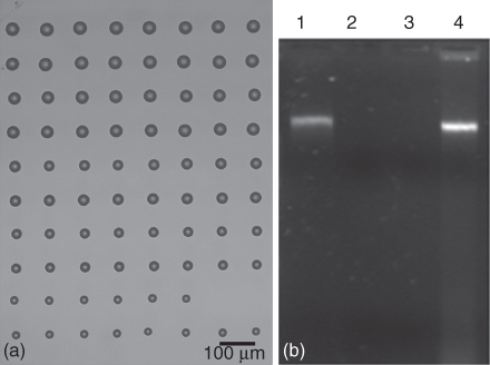
Figure 14.1 (a) Optical microscopy image of a DNA microarray printed by LIFT on glass. Laser fluence increases from bottom to top of the image: each laser fluence (1, 1.5, 2, 2.5, 3 mJ/cm2) is applied to deposit two rows of droplets. (b) Agarose gel electrophoresis (1) 3 mJ/cm2, (2) 4 mJ/cm2, (3) 5 mJ/cm2 laser fluence, and (4) DNA control 12 ng/µl [51].
Furthermore, in order to surmount the difficulties characteristic of the conventional LIFT, an original idea, which allows the direct printing of biological solutions without the need for preparing the liquid in thin-film form, has been developed [52]. This technique, called film-free LIFT (a detailed description is provided in Chapter 6) relies on strongly focusing a femtosecond pulsed laser beam inside the liquid to be printed just below the free surface. A cavitation bubble is generated, which projects a small fraction of the liquid beyond the free surface, thus the liquid being deposited on a substrate as a printed droplet. The displacement of the substrate with respect to the free surface allows the realization of micropatterns. This technique has been proved to be feasible for biomolecules printing, that is, functional DNA and protein microarrays [53, 54].
14.3 LIFT of Biomolecules
14.3.1 Streptavidin and Avidin–Biotin Complex
Among the numerous biomolecules involved in the development of a controlled immobilization in a biomicrodevice configuration, proteins are particularly challenging. In contrast with DNA, for which suitable immobilization technologies have been developed and DNA microchips commercialized, technology allowing uniform and global attachment of a wide variety of proteins to different surfaces is not currently available. This lag in technology arises from the fundamental structural difference between DNA and proteins, the latter being complex three-dimensional biomolecules with many attachment sites, which can lose their bioactivity if their structure is disrupted during the immobilization process or due to random orientation of the immobilized protein.
The first works on protein printing are presented in [55, 56], where the authors report on an alternative to LIFT, that is, matrix-assisted pulsed laser evaporation–direct write (MAPLE-DW) (for details on LIFT basics and its alternatives, please refer to Chapter 1) for the deposition of (i) a mixture of banana tissue with mineral oil and graphite powder for the fabrication of electrochemical sensors and (ii) a functional bovine serum albumin (BSA) biomolecule microarray. In [57], the same group from the Naval Research Laboratory reports on the application of MAPLE DW for the fabrication of bioactive and regular microarrays of streptavidin. In the same work, a comparison with the soft lithography microprinting technique is provided. The authors explored the direct immobilization, morphology, and function of the deposited protein at the interface with an aqueous environment and in the presence of controlled ligand–receptor reactions. The advantages of the laser techniques applied in comparison with the soft lithography microprinting were evident, that is, the patterns obtained via laser-based techniques showed a reduction in size and well-defined patterns.
These first successes on biomolecule printing prompted an extensive number of different protein types being printed through LIFT, as, for example, the biotin–avidin complex.
Avidin is a glycoprotein found in egg whites that contains four identical subunits, each having one binding site for biotin (or vitamin H). Streptavidin is a biotin-binding protein isolated from Streptomyces avidinii, which contains four subunits, each with a single biotin-binding site [58]. Both proteins are very stable and can tolerate a wide range of buffer conditions, pH, and chemical modifications and can be conjugated to other proteins or labeled with various detection agents without loss of binding activity.
Further on, based on the fact that the biospecificity and strength of the biotin–avidin noncovalent interaction make this system very useful for the micropatterning of biomolecules [59], nanosecond and femtosecond lasers were used to obtain micron-size patterns of biotin and avidin. The laser parameters, the influence of the solution viscosity, and the receiving surface wettability on the formed patterns were investigated and optimized. The size of the transferred patterns was controlled by the spot dimensions and energy of the laser beam, thickness of the donor (liquid) layer, glycerol percentage in the composition of the donor, and surface wettability. Moreover, a regular transfer of droplets was possible for distances greater than few micrometers, and different percentages of glycerol could be added without the risk of contamination. The pattern functionality after laser transfer was confirmed by using a three-step strategy: (i) direct transfer of coupling molecules using LIFT, (ii) immobilizing an active complementary protein on it, and (iii) performing direct and/or indirect labeling by fluorescence microscopy assay [60]. In order to exploit the direct labeling interaction, biotin was linked to the surface of the substrate using LIFT and then used as a site for the specific recognition of the Atto-565-Streptavidin as shown in Figure 14.2.

Figure 14.2 Strategy implying the direct and indirect labeling by fluorescence microscopy assays for the functional biotin patterns obtained by LIFT in a perfusion chamber. (a) The perfusion chamber was built from cleaned Corning cover glass and the patterned cover glass separated by a double-side tape spacer (red). (b) The direct labeling was based on one-step antibody–biotin coupling. (c) The indirect labeling was based on the fluorescent marked Atto-565-Streptavidin–biotin coupling. After incubation with the fluorescence labeling solution, all the samples were rinsed with PBS and distilled water. Fluorescence was detected using a Zeiss fluorescence microscope equipped with a Laser Scanning System Radiance 2100 (400–700 nm) and with a Carl Zeiss Axio Camera HR, and the signal intensity was quantified.
For the indirect labeling strategy, two different protein–ligand systems were used: avidin, biotin, and Atto-565-Streptavidin, and titin I band fragment human recombinant – monoclonal anti-titin antibody-cy 5 goat anti-mouse IgG conjugate antibody [60] respectively.
An important aspect in the miniaturization of the patterns was given by the wetting properties of the receiving surfaces (see Figure 14.3).
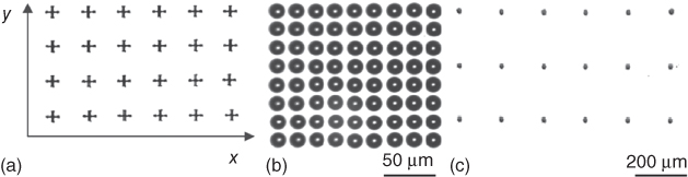
Figure 14.3 (a) Pattern diagram for obtaining spots onto different surfaces, that is, hydrophilic/hydrophobic. (b) 10 µm spot spacing on hydrophilic surfaces (glass). (c) 200 µm or more on hydrophobic surfaces (Ormocer). The spots were captured immediately after printing, the spot diameter and their spacing on the substrate were measured.
The wettability aspect enabled reproducible printing of microarrays with spacing between spots from 10 to 200 µm or more as it can also be seen in Figure 14.3. The diameter of the spots on the hydrophilic surfaces was 20 µm resulting in a theoretical spot-to-spot distance of less than 10 µm. In the case of the hydrophobic surfaces (Ormocer), this distance could be optimized. However, this parameter was tolerable, because even in the worst case, no mixing of spots could occur.
Furthermore, by varying the laser energy and the donor solution viscosity (from 0% to 70% (v/v) of a glycerol/water solvent) together with the receiver substrates (hydrophobic surfaces), micropatterns with droplets as small as 8 µm could be obtained [37, 61]. Therefore, enzyme solution properties, that is, viscosity and surface tension enable LIFT as a suitable method for biological compound patterning. The efficiency of LIFT was not affected by the addition of glycerol in a percentage up to 70%, which contributed to the stabilization of the microarray patterns and the increase of their resolution.
Another important key factor in protein patterning is the spot uniformity. Depending on the solutions used for donor preparation, especially when glycerol and surfactants are missing, a ring-like morphology can appear within the printed spots (see Figure 14.4). The ring structure in the spot morphology is commonly seen in protein or antibody microarrays, and it results from the transport of protein molecules that are accumulated at the air/water interface in the perimeter of the droplet on a solid surface. This effect becomes increasingly significant as the droplet size decreases. One can eliminate the ring structure by adding competitive surfactants to the protein solution or by designing facile surface reactions for protein immobilization.
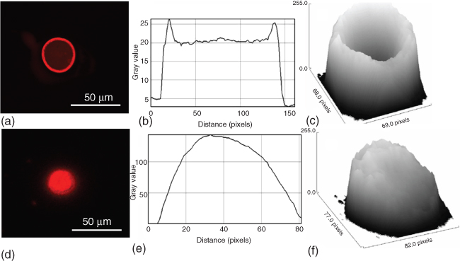
Figure 14.4 From left to right (a–c) without SDS, (d–f) with SDS. (a) and (d) Fluorescence microscopy images of photobiotin spots immobilized onto an Ormocer slide. (b) and (e) Cross-sectional profiles of the images (a) and (d), respectively. (c) and (f) Profiles of the surfaces shown in (a) and (d).
The effect of the nanosecond and femtosecond laser pulse lengths has been studied in relation to the preservation of the activity of the transferred biomolecules. LIFT has been employed for microarray printing of liquid solutions of both the enzyme Horseradish Peroxidase (HRP) and the titin protein on nitrocellulose solid surfaces, as shown in Figure 14.5 [37]. The quantification of the active biomolecules has been carried out by Bradford assay, quantitative colorimetric enzymatic assay, and fluorescence techniques. Spectrophotometric measurements of the HRP and the titin activity as well as chromatography and fluorescence assay studies have revealed a connection between the properties of the deposited biologically active biomolecules, the experimental conditions, and the target composition. The bioassays have shown that up to 78% of the biomolecules remained active after femtosecond laser transfer, while this value was reduced to 54% after ns laser transfer.
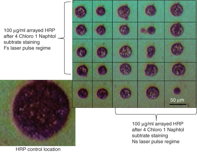
Figure 14.5 HRP transfer at a laser fluence of 260 mJ/cm2.
(Dinca et al. 2008 [37]. Reproduced with permission of Springer.)
In a more recent paper, [62] the authors present the successful transfer of untagged and enzyme-linked antibodies on cellulose-based filter paper receivers for future developments in point-of-care diagnostic devices. The functionality of the laser transferred biomolecules (mouse IgG and anti-mouse IgG tagged with HRP) was demonstrated by carrying out a colorimetric enzyme-linked immunosorbent assay (ELISA), which proved that LIFT is a technique capable of transferring antibodies accurately and with high reproducibility onto unconventional substrates for the fabrication of immunologic paper-based sensors.
Not only 2D but also 3D biomolecule patterning using laser-based techniques, which enable the construction of arbitrary two- and three-dimensional shapes, not restricted to array-based shapes, was demonstrated in [63]. 3D patterning implied the immobilization and activation of photobiotin on the surface of the 3D Ormocer structures and further binding specifically to fluorescently labeled streptavidin.
Avidin was also used as homobifunctional protein adapter for directed three-dimensional patterning of self-assembled amyloid fibrils. In this case, each protein molecule could simultaneously bind to a photobiotin-functionalized substrate, and the biotinylated molecules on the opposite face were exposed to solution as seed, or “anchoring point.” The covalent bond formation between the iodoacetamide group in the biotin derivative and the thiol group in the fibrils containing cysteine allowed specific 3D peptides patterning [64].
14.3.2 Amyloid Peptides
Amyloid peptides have the characteristic of self-assembling, and in addition, they may be deposited by LIFT on specific positions and different surfaces. Therefore, it is possible to enable the specific fabrication of a huge number of different structures aiming at many important applications in medicine and biology [65].
LIFT was used for microarray fabrication of self-assembled octapeptides derived from sequences of a natural fibrous protein (i.e., the adenovirus fiber). No influence on the peptide fibril self-assembly process and/or fibril stability at the solid/solution interface has been observed after LIFT.
As previously mentioned, the transferred patterns' size and shape are directly correlated to the laser pulse energy used; for energies close to the threshold energy, the transfer was uniform and no splashes were observed as shown in Figure 14.6.

Figure 14.6 Peptide micropatterns transferred by LIFT and stained using Thioflavin T diagnostic tests. Scale bar is 50 µm.
Well-defined patterns of peptides on gold-coated glass were obtained, and the larger spots, with diameters of 120 µm, allowed a better observation of the peptide fibril formation during drying, as shown in Figure 14.7.

Figure 14.7 Scanning electron microscopy image of part of (a) a printed peptide array and (b) one peptide droplet transferred by LIFT on a gold surface when the samples is left to dry in air, at room temperature after deposition. The presence of flat and elongated aggregates, 2–6 µm long and 0.2–0.5 µm thick peptide tapes can be noticed.
LIFT provides the possibility to pattern peptide-based arrays, which could be used as flexible and powerful tool in basic biology studies of protein recognition and function, peptides–other biocompounds (enzymes, proteins, DNA, small molecules) interactions, but also for the 2D and 3D templating of inorganic materials and incorporation and display of ligands critical for cell attachment and growth.
14.3.3 Odorant-Binding Proteins
Protein printing is important for applications aiming at the fabrication of not only functional microarrays but also biosensors, in particular for the detection of contaminants in food, essential to avoid risks for humans [66]. An extensive review of laser printing of chemical and biological sensors is presented in Chapter 13. In recent studies [67, 68], the possibility of depositing biomolecule-containing solutions, that is, odorant-binding proteins (OBPs), through LIFT onto the active area of a surface acoustic (SAW) device for the development of a bioelectronic nose was presented. The sensing system proposed by the authors exploited the high sensitivity and fast response time typical of SAW-based sensors in combination with the adaptable selectivity of the OBPs [60]. OBPs are small extracellular proteins that belong to the lipocalin superfamily [69, 70]. They have an important role in odor detection by carrying, deactivating, and/or selecting the odorant molecules [71, 72].
The “bioelectronic nose” fabricated in [67] was based on three SAW resonators coated through LIFT with three different OBPs, characterized by different binding specificities, plus an uncoated SAW device used as reference. The selected proteins were the wild-type OBP from bovine (wtbOBP), a double mutant of the OBP from bovine (dmbOBP), and the wild-type OBP from pig (wtpOBP). To demonstrate the functionality of the biosensor arrays, the SAW devices coated by LIFT were exposed to different concentrations of octanol and carvone, two odorant compounds largely used in the food industry.
It was found that LIFT it is an appropriate technique for OBP deposition with a very high lateral resolution (Figure 14.8a,b), which allowed the fabrication of functional SAW biosensor arrays. The SAW biosensor arrays fabricated by LIFT were capable of detecting specific odors with sensitivity and detection limit similar to those that could be obtained with more conventional methods, but with a much lower consumption of detecting agent (Figure 14.8c,d). These results demonstrate that LIFT is a powerful technique to fabricate biosensors with ultimate applications in the assessment of food contamination by molds or for the evaluation of indoor air quality in buildings.

Figure 14.8 Optical microscopy images of SAW sensors printed by LIFT, by overlapping individual droplets at different center-to-center distances (ratio of overlapped length between two neighboring droplets to the individual droplet diameter (a) 30% overlap, (b) 50% overlap. (c) Comparison between sensitivities to octanol and carvone detection of the wtbOBP-, dmbOBP-, and wtpOBP-based biosensors. (d) Biplot of loadings and scores using the first two components of the principal component analysis.
(Reproduced with permission from [67].)
14.3.4 Liposomes
Similarly to DNA and protein printing, liposome printing also represents an important area of research. Liposome patterns are used in applications such as carrier systems of drugs or other functional substances and miniaturized biosensors.
Liposomes are molecular structures consisting of lipid bilayers that enclose an aqueous core. The most important properties of liposomes are, for example, nontoxicity, biodegradability, the easy preparation (or production), and stability in solution for a long period of time.
In [73], liposome-containing solutions were printed by LIFT assisted by a DRL (or sacrificial layer). This layer consists of a photodegradable polymer, namely a TP. For details on LIFT assisted by a TP, please refer to Chapter 3. The TP was chosen as DRL layer, due to the fact that the emission wavelength of the lasers used for LIFT matches the absorption maxima of the TP. The specific TP was synthesized following the procedure published previously [74].The TP was deposited by spin coating. TP films with a thickness of 60, 150, and 350 nm were obtained with this procedure and subsequently used for transfer experiments.
The donor solutions used for LIFT in [73] contained giant liposomes with diameters of tens of micrometers, which were obtained by the “gentle hydration method” and by the rotoevaporation method. A phase-contrast microscopy image and a fluorescence microscopy image of giant liposomes in solution, that is, the donor solution prior to LIFT, are shown in Figure 14.9. The transfer was performed using two laser systems, a XeCl (308 nm) and an ArF (193 nm) excimer laser.
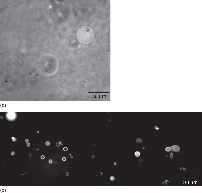
Figure 14.9 Phase-contrast microscopy image (a) and fluorescence microscopy image (b) of giant liposomes in solution.
(Palla-Papavlu et al. 2011 [73]. Reproduced with permission of Springer.)
It was found that a major role in the transfer process of the liposome-containing solution was played by the thickness of the TP layer. The data suggested that in the case of TP-LIFT with the 193 nm laser system, it was not possible to print a regular array with a 60 nm intermediate TP layer, and that only a 150 nm thick TP layer was sufficient to minimize the damages to the transferred liquid layer. In addition, the laser fluences necessary to transfer regular droplets need to be higher than the fluences needed for the complete vaporization of the TP layer (35 mJ/cm2). Further experiments, with a XeCl, laser system operating at 308 nm, showed that circular droplets with a well-defined contour could be obtained even for a 60 nm thick TP layer. Another important parameter for printing droplets with high resolution, reproducibility, and integrity of the biomolecules was the laser fluence. Fluorescence microscopy was used to determine whether the integrity of the liposomes was altered after laser transfer. A fluorescence image of a microarray obtained at different laser fluences (for ArF laser irradiation) is presented in Figure 14.10. Only at fluences between 40 and 80 mJ/cm2, the transferred spots exhibited fluorescence with an intensity corresponding to the target solution. The transferred spots were not surrounded by splashes for fluences between 40 and 60 mJ/cm2, while for fluences up to 80 mJ/cm2, random droplets appeared on the substrate. Above 80 mJ/cm2, no fluorescence was detected anymore, suggesting that in this case, the liposomes may have degraded due to the high laser fluences.

Figure 14.10 Fluorescence image of a microarray of liposome solution obtined at different laser fluences.
(Palla-Papavlu et al. 2011 [73]. Reproduced with permission of Springer.)
In addition, to further investigate the chemical composition of the liposomes after the laser transfer, micro-Raman spectroscopy was used. The μ-Raman reference spectrum (Figure 14.11) of the liposomes agrees well with literature data, although it had a lower signal-to-noise ratio than for reported data [75]. Raman spectra of transferred liposomes using different laser fluences (Figure 14.11) showed a clear trend: the intensity of characteristic Raman peaks decreased with increasing laser fluence. In addition, there were no indications of TP or TP fragments being present in the transferred liposomes. The Raman analysis suggested that the liposomal membranes were not damaged for laser fluences below 60 mJ/cm2 and that the TP did probably not contaminate the lipids.
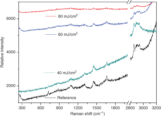
Figure 14.11 Raman spectra of the liposome solution after transfer at different laser fluences.
(Palla-Papavlu et al. 2011 [73]. Reproduced with permission of Springer.)
The fact that liposome arrays could be produced in a cost- and time-effective way with a minimum sample volume suggested that LIFT is a promising technique for transferring liposome solutions, which could therefore be used for in vitro and in vivo applications.
14.4 Conclusions and Perspectives
For many applications in the area of biosensors, tissue engineering, and regenerative medicine, it is important to develop a new generation of high-performance biomaterials, where their interfacial properties could be controlled and modulated toward the required application. Although significant progress has been achieved in the field of material printing and patterning, the materials and methods discussed within this chapter still have limitations in practical applications that need to be overcome in the future.
This chapter summarizes some applications and developments in the field of LIFT of biomolecules. The data shown suggest that LIFT is a promising approach for printing DNA, proteins (avidin, streptavidin), peptides, and lipids either in solution or as dry thin films that can be utilized for the fabrication of functional microarrays, biosensors, or drug delivery systems. The transfer process of the biological materials can be optimized by modifying the process parameters, that is, laser wavelength, laser fluence, applying intermediate DRLs with varying thickness, or using different types of substrates. As it has been shown in different studies, the target–substrate distance is a parameter that does not influence the morphology of the obtained micropatterns.
Considering the aforementioned advantages of the LIFT technique on depositing materials with very high resolution onto different types of substrates, one could envision that this approach could provide a new strategy to engineer functional multicompositional platforms to be used for regenerative biomedicine and tissue engineering studies, which could ultimately be extended toward industrial applications.
Future research in the field of LIFT could also be directed toward biomimetic biointerfaces, with integrated analysis platforms able to address the complexity of bioenvironments according to the desired application.
Acknowledgments
This work was supported by the National Program 4N/2016 and grants of the Romanian National Authority for Scientific Research and Innovation, CNCS – UEFISCDI, project number PN-II-RU-TE-2014-4-2311, PN-II-PT-PCCA-2013-4-1643, PNII-PT-PCCA-2013-4-1992, and PN-II-RU-TE-2014-4-2434.
Conflict of Interest
The authors declare no competing interests.
References
- 1 Ozbolat, I.T., Peng, W., and Ozbolat, V. (2016) Application areas of 3D bioprinting. Drug Discovery Today, 21 (8), 1257–1271.
- 2 Terry, S.C., Jerman, J.H., and Angell, J.B. (1979) A gas chromatography air analyzer fabricated on a silicon wafer. IEEE Trans. Electron. Dev., 26, 1880–1886.
- 3 Voldman, J., Gray, M.L., and Schmidt, M.A. (1999) Microfabrication in biology and medicine. Annu. Rev. Biomed. Eng., 1, 401–425.
- 4 Gaharwar, A.K., Arpanaci, A., Andersen, T.L., and Dolatshahi-Pirouz, A. (2016) 3D biomaterial microarray for regenerative medicine: current state of the art, emerging directions and future trends. Adv. Mater., 27, 771–781.
- 5 Vo-Dinh, T. (2005) Methods in Molecular Biology, Protein Nanotechnology, Protocols, Instrumentation, and Applications, vol. 300, Humana Press Inc., Totowa, NJ, p. 101.
- 6 Borini, S., Staiano, M., Rocchia, M., Rossi, A.M., and D'Auria, S. (2007) Advanced nanotechnological approaches for designing protein-based “Lab-on-Chips” sensors on porous silicon wafer. Recent Pat. DNA Gene Seq., 1, 1–7.
- 7 Gutmann, O., Niekrqwietz, R., Steinert, C.P., Sandmaier, H., Messner, S., de Heij, B., Daub, M., and Zengerle, R. (2003) Droplet release in a highly parallel pressure driven nanoliter dispenser. IEEE Trans., 364–367.
- 8 Ekins, R. and Chu, F.W. (1999) Microarrays: their origins and applications. Trends Biotechnol., 17 (6), 217–218.
- 9 Haab, B.B., Dunham, M.J., and Brown, P.O. (2001) Protein microarrays for highly parallel detection and quantitation of specific proteins and antibodies in complex solutions. Genome Biol., 2 (2), 0004.1–0004.13.
- 10 Seong, S. and Choi, C. (2003) Current status of protein chip development in terms of fabrication and application. Proteomics, 3, 2176–2189.
- 11 Blawas, A.S. and Reichert, W.M. (1998) Protein patterning. Biomaterials, 19, 595–609.
- 12 Blawas, A.S., Oliver, T.F., Pirrung, M.C., and Reichert, W.M. (1998) Step-and-repeat photopatterning of protein features using caged-biotin-BSA: characterization and resolution. Langmuir, 14, 4243–4250.
- 13 Khademhosseini, A., Eng, G., Kucharczyk, P.A., Langer, R., Vunjak-Novakovic, G., and Radisic, M. (2007) Microfluidic patterning for fabrication of contractile cardiac organoids. Biomed. Microdevices, 9, 149–157.
- 14 Martin, B.D., Gaber, B.P., Patterson, C.H., and Turner, D.C. (1998) Direct protein microarray fabrication using a hydrogel “stamper”. Langmuir, 14, 3971–3975.
- 15 Roda, A., Guardigli, M., Russo, C., Pasini, P., and Baraldini, M. (2000) Protein microdeposition using a conventional ink-jet printer. BioTechniques, 28, 492–496.
- 16 Howard, E.I. and Cachau, R.E. (2002) Ink-jet printer heads for ultra-small-drop protein crystallography. BioTechniques, 33, 1302–1306.
- 17 Braudy, R.S. (1969) Laser writing. Proc. IEEE, 57, 1771–1772.
- 18 Levene, M.L., Scott, R.D., and Siryj, B.W. (1970) Material transfer recording. Appl. Opt., 9 (10), 2260–2265.
- 19 Brisbane, A.D. (1971) Pattern deposit by laser. US Patent 3,560,258, filed and issued May 31, 1967 issued Feb. 2, 1971.
- 20 Bohandy, J., Kim, B.F., and Adrian, F.J. (1986) Metal deposition from a supported metal film using an excimer laser. J. Appl. Phys., 60 (4), 1538–1539.
- 21 Bohandy, J., Kim, B.F., Adrian, F.J., and Jette, A.N. (1988) Metal deposition at 532 nm using a laser transfer technique. J. Appl. Phys., 63 (4), 1158–1162.
- 22 Baseman, R.J., Froberg, N.M., Andreshak, J.C., and Schlesinger, Z. (1990) Minimum fluence for laser blow-off of thin gold films at 248 and 532 nm. Appl. Phys. Lett., 56, 1412–1414.
- 23 Schultze, V. and Wagner, M. (1991) Laser induced forward transfer of aluminium. Appl. Surf. Sci., 52, 303–309.
- 24 Kantor, Z., Zs, T., and Szorenyi, T. (1992) Laser induced forward transfer: the effect of support-film interface and film to substrate distance on transfer. Appl. Phys. A, 54, 170–175.
- 25 Kantor, Z., Zs, T., Szorenyi, T., and Toth, A.L. (1994) Deposition of micrometer-sized tungsten patterns by laser transfer technique. Appl. Phys. Lett., 64, 3506–3508.
- 26 Sano, T., Yamada, H., Nakayama, T., and Miyamoto, I. (2002) Experimental investigation of laser induced forward transfer process of metal thin films. Appl. Surf. Sci., 186, 221–226.
- 27 Toth, Z., Szorenyi, T., and Toth, A.L. (1993) Ar+ laser induced forward transfer (LIFT): a novel method for micrometer size surface patterning. Appl. Surf. Sci., 69, 317–320.
- 28 Zergioti, I., Mailis, S., Vainos, N.A., Papakonstantinou, P., Kalpouzos, C., Grigoropoulous, C.P., and Fotakis, C. (1998) Microdeposition of metal and oxide structures using ultrashort laser pulses. Appl. Phys. A, 66, 579–582.
- 29 Zergioti, I., Papazoglu, D.G., Karaiskou, A., Fotakis, C., Gamaly, E., and Rode, A. (2003) A comparative schlieren imaging study between ns and sub-ps laser induced forward transfer of Cr. Appl. Surf. Sci., 208-209 (1), 177–180.
- 30 Banks, D.P., Grivas, C., Mills, J.D., Eason, R.W., and Zergioti, I. (2006) Nanodroplets deposited in microarrays by femtosecond Ti:sapphire laser induced forward transfer. Appl. Phys. Lett., 89, 19107-(1–3).
- 31 Papakonstantinou, P., Vainos, N.A., and Fotakis, C. (1999) Microfabrication by UV femtosecond laser ablation of Pt, Cr and indium oxide thin films. Appl. Surf. Sci., 151, 159–170.
- 32 Greer, J.A. and Parker, T.E. (1988) Laser induced forward transfer of metal oxides to trim the frequency of surface acoustic wave resonator devices. SPIE Proc., 998, 113–125.
- 33 Zergioti, I., Papazoglu, D.G., Karaiskou, A., Vainos, N.A., and Fotakis, C. (2002) Laser microprinting of InOx active optical structures and time resolved imaging of the transfer process. Appl. Surf. Sci., 197–198, 868–872.
- 34 Chakraborty, S., Sakata, H., Yokoyama, E., Wakaki, M., and Chakravorty, D. (2005) Laser induced forward transfer technique for maskless patterning of amorphous V2O5 thin film. Appl. Surf. Sci., 254, 638.
- 35 Klini, A., Mourka, A., Dinca, V., Fotakis, C., and Claeyssens, F. (2007) ZnO nanorod micropatterning via laser induced forward transfer. Appl. Phys. A, 87 (1), 17–22.
- 36 Fogarassy, E., Fuchs, C., Kerherve, F., Hauchecorne, G., and Perrière, J. (1989) Laser-induced forward transfer: a new approach for the deposition of high Tc superconducting thin films. J. Mater. Res., 4, 1082–1086.
- 37 Dinca, V., Ranella, A., Farsari, M., Kafetzopoulous, D., Dinescu, M., Popescu, A., and Fotakis, C. (2008) Quantification of the activity of biomolecules in microarrays obtained by direct laser transfer. Biomed. Microdevices, 10, 719–725.
- 38 Fernandez-Pradas, J.M., Colina, M., Serra, P., Domınguez, J., and Morenza, J.L. (2004) Laser induced forward transfer of biomolecules. Thin Solid Films, 27, 453–454C.
- 39 Chrisey, D.B. (2000) The power of direct writing. Science, 289 (5481), 879–881.
- 40 Karaiskou, A., Zergioti, I., Fotakis, C., Kapsetaki, M., and Kafetzopoulos, D. (2003) Microfabrication of biomaterials by the sub-ps laser induced forward transfer process. Appl. Surf. Sci., 208, 245–249.
- 41 Zergioti, I., Papazoglou, D.G., Karaiskou, A., Fotakis, C., Kapsetaki, E., and Kafetzopoulos, D. (2005) Femtosecond laser microprinting of biomaterials. Appl. Phys. Lett., 86, 163902-(1–3).
- 42 Serra, P., Colina, M., Fernandez-Paras, J.M., Sevilla, L., and Morenza, J.L. (2004) Preparation of functional DNA microarrays by laser induced forward transfer. Appl. Phys. Lett., 85, 1639–1641.
- 43 Doraiswamy, A., Narayan, R.J., Lippert, T., Urech, L., Wokaun, A., Nagel, M., Hopp, B., Dinescu, M., Modi, R., Auyeung, R.C.Y., and Chrisey, D.B. (2006) Excimer laser forward transfer of mammalian cells using a novel triazene absorbing layer. Appl. Surf. Sci., 252, 4743–4747.
- 44 Chrisey, D.B., Piqué, A., McGill, R.A., Horwitz, J.S., Ringeisen, B.R., Bubb, D.M., and Wu, P.K. (2003) Laser deposition of polymer and biomaterial films. Chem. Rev., 103 (2), 553–576.
- 45 Dinca, V., Fardel, R., Di Pietrantonio, F., Cannatà, D., Benetti, M., Verona, E., Palla-Papavlu, A., Dinescu, M., and Lippert, T. (2010) Laser induced forward transfer: an approach to single-step polymer microsensor fabrication. Sens. Lett., 8 (3), 436–440.
- 46 Boutopoulos, C., Tsouti, V., Goustouridis, D., Chatzandroulis, S., and Zergiotti, I. (2008) Liquid phase direct laser printing of polymers for chemical sensing applications. Appl. Phys. Lett., 93, 191109-(1–3).
- 47 Fardel, R., Nagel, M., Nuesch, F., Lippert, T.K., and Wokaun, A. (2007) Laser forward transfer using a sacrificial layer: Influence of the material properties. Appl. Surf. Sci., 254, 1322–1326.
- 48 Nagel, M., Fardel, R., Feurer, P., Häberli, M., Nüesch, F., Lippert, T.K., and Wokaun, A. (2008) Aryltriazene photopolymer thin films as sacrificial release layers for laser-assisted forward transfer systems: study of photoablative decomposition and transfer behavior. Appl. Phys. A, 92, 781–789.
- 49 Kattamis, N.T., Purnick, P.E., Weiss, R., and Arnold, C.B. (2007) Thick film laser induced forward transfer for deposition of thermally and mechanically sensitive materials. Appl. Phys. Lett., 91, 171120-(1–3).
- 50 Serra, P., Duocastella, M., Fernandez-Pradas, J.M., and Morenza, J.L. (2010) in Cell and Organ Printing (eds B.R. Ringeisen et al.), Springer, pp. 53–80.
- 51 Palla-Papavlu, A., Dinca, V., Lippert, T., and Dinescu, M. (2011) Laser induced forward transfer for materials patterning. Rom. Rep. Phys., 63, 1285–1301.
- 52 Duocastella, M., Patrascioiu, A., Fernandez-Pradas, J.M., Morenza, J.L., and Serra, P. (2010) Film-free forward printing of transparent and weakly absorbing liquids. Opt. Express, 18 (21), 21815–21825.
- 53 Duocastella, M., Fernandez-Pradas, J.M., Morenza, J.L., Zafra, D., and Serra, P. (2010) Novel laser printing technique for miniaturized bisosensor preparation. Sens. Actuators, B, 145 (1), 596–600.
- 54 Patrascioiu, A., Duocastella, M., Fernandez-Pradas, J.M., Morenza, J.L., and Serra, P. (2011) Liquids microprinting through a novel film-free fs laser based technique. Appl. Surf. Sci., 257 (12), 5190–5194.
- 55 Wu, P.K., Ringeisen, B.R., Callahan, J. et al. (2001) The deposition, structure, pattern deposition, and activity of biomaterial thin-films by matrix-assisted pulsed-laser evaporation (MAPLE) and MAPLE direct write. Thin Solid Films, 398–399, 607–614.
- 56 Ringeisen, B.R., Wu, P.K., Kim, H. et al. (2002) Picoliter-scale protein microarrays by laser direct write. Biotechnol. Progr., 18, 1126–1129.
- 57 Dinu, C.Z., Dinca, V., Howard, J., and Chrisey, D.B. (2007) Printing technologies for fabrication of bioactive and regular microarrays of streptavidin. Appl. Surf. Sci., 253 (19), 8119–8124.
- 58 Wilchek, M. and Bayer, E.A. (eds) (1990) Introduction to avidin–biotin technology, vol. 184, Elsevier, pp. 3–15.
- 59 Green, N. (1975) Avidin. Adv. Protein Chem., 29, 85–133.
- 60 Dinca, V., Farsari, M., Kafetzopoulos, D., Popescu, A., Dinescu, M., and Fotakis, C. (2008) Patterning parameters for biomolecules microarrays constructed with nanosecond and femtosecond UV lasers. Thin Solid Films, 516 (18), 6504–6511.
- 61 Dinca, V., Ranella, A., Popescu, A., Dinescu, M., Farsari, M., and Fotakis, C. (2007) Parameters optimization for biological molecules patterning using 248-nm ultrafast lasers. Appl. Surf. Sci., 254, 1164–1168.
- 62 Katis, I.N., Holloway, J.A., Madsen, J., Faust, S.N., Garbis, S.D., Smith, P.J.S., Voegeli, D., Bader, D.L., Eason, R.W., and Sones, C.L. (2014) Paper-based colorimetric enzyme linked immunosorbent assay fabricated by laser induced forward transfer. Biomicrofluidics, 8, 036502-(1–9).
- 63 Farsari, M., Dinca, V., Dinescu, M., Georgiou, S., and Fotakis, C. (2007) Construction of 2D and 3D biomolecules structures using fs lasers. Int. J. Nanomanuf., 1 (6), 762–770.
- 64 Dinca, V., Kasotakis, E., Catherine, J., Mourka, A., Ranella, A., Ovsianikov, A., Chichkov, B.N., Farsari, M., Mitraki, A., and Fotakis, C. (2008) Directed three-dimensional patterning of self-assembled peptide fibrils. Nano Lett., 8 (2), 538–543.
- 65 Dinca, V., Kasotakis, E., Catherine, J., Mourka, A., Mitraki, A., Popescu, A., Dinescu, M., Farsari, M., and Fotakis, C. (2007) Development of peptide-based patterns by laser transfer. Appl. Surf. Sci., 254 (4), 1160–1163.
- 66 McGrath, T.F., Andersson, K., Campbell, K., Fodey, T.L., and Elliott, C.T. (2013) Development of a rapid low cost fluorescent biosensor for the detection of food contaminants. Biosens. Bioelectron., 41, 96–102.
- 67 Di Pietrantonio, F., Benetti, M., Cannatà, D., Verona, E., Palla-Papavlu, A., Fernández-Pradas, J.M., Serra, P., Staiano, M., Varriale, A., and D'Auria, S. (2015) A surface acoustic wave bio-electronic nose for detection of volatile odorant molecules. Biosens. Bioelectron., 67, 516–523.
- 68 Palla-Papavlu, A., Patrascioiu, A., Di Pietrantonio, F., Fernández-Pradas, J.-M., Cannatà, D., Benetti, M., D'Auria, S., Verona, E., and Serra, P. (2014) Preparation of surface acoustic wave odor sensors by laser-induced forward transfer. Sens. Actuators, B, 192, 369–377.
- 69 Ramoni, R., Bellucci, S., Grycznyski, I., Grycznyski, Z., Grolli, S., Staiano, M., De Bellis, G., Micciulla, F., Pastore, R., and Tiberia, A. (2007) The protein scaffold of the lipocalin odorant-binding protein is suitable for the design of new biosensors for the detection of explosive components. J. Phys. Condens. Matter, 19, 395012-(1–7).
- 70 Lobel, D., Jacob, M., Volkner, M., and Breer, H. (2002) Odorants of different chemical classes interact with distinct odorant binding protein subtypes. Chem. Senses, 27, 39–44.
- 71 Spinelli, S., Ramoni, R., Grolli, S., Bonicel, J., Cambillau, C., and Tegoni, M. (1998) The structure of the monomeric porcine odorant binding protein sheds light on the domain swapping mechanism. Biochemistry, 37, 7913–7918.
- 72 Tegoni, M., Ramoni, R., Bignetti, E., Spinelli, S., and Cambillau, C. (1996) Domain swapping creates a third putative combining site in bovine odorant binding protein dimer. Nat. Struct. Biol., 3 (10), 863–867.
- 73 Palla-Papavlu, A., Paraico, I., Shaw-Stewart, J., Dinca, V., Savopol, T., Kovacs, E., Lippert, T., Wokaun, A., and Dinescu, M. (2011) Liposome micropatterning based on laser-induced forward transfer. Appl. Phys. A, 102, 651–659.
- 74 Lippert, T., Wokaun, A., Stebani, J., Nuyken, O., and Ihlemann, J. (1993) Triazene polymers designed for excimer laser ablation. Angew. Makromol. Chem., 206, 97–110.
- 75 Cherney, D.P., Conboy, J.C., and Harris, J.M. (2003) Optical-trapping Raman microscopy detection of single unilamellar lipid vesicles. Anal. Chem., 75 (23), 6621–6628.