
Chapter 16
Industrial, Large-Area, and High-Throughput LIFT/LIBT Digital Printing
Guido Hennig1, Gerhard Hochstein2 and Thomas Baldermann1
1Daetwyler Graphics AG, Flugplatz, 3368 Bleienbach, Switzerland
2Terra Incognita Innovationsmanagement GmbH, Kastanienweg 8, 57392 Schmallenberg-Bad, Fredeburg, Germany
16.1 Introduction
The graphics industry has been facing its digital revolution since the 1990s, resulting in digital printing systems replacing partly conventional printing machines. A broad range of digital printing techniques is available today. Nevertheless, a lot of demands for the printing of special inks have been not yet fulfilled by today's digital printing methods, leaving space for the introduction of new technologies. Identifying suitable business models for industrial use of LIFT/LIBT applications is an ongoing process. Initial approaches have been undertaken in the area of graphical and functional printing within the first and early second decades of the 2000s. Emerging markets of this era such as mass production of solar cells bore challenges for advanced coating technologies for conductive and semiconductive layers. Functional applications such as heating elements or antennas on automotive glass windshields and windows require transfer technologies for printing of conductive structures with high solid content, high viscosity, and high volume transfer. Traditional printing techniques such as screen printing cause high fixed costs prior to the first copy, thus prototyping, low volume orders, and individualization of functional goods are cost-ineffective. Typical digital printing systems are rather limited in terms of big volume transfer of conductive and other technical materials, which might be an area for implementation of the here described LIFT/LIBT-production solutions. Meanwhile, the development of industrial solutions for the aforementioned applications left the status of venture capital investments. Nowadays, small and medium enterprises (SME) are trying to enter markets with highly specified LIFT/LIBT machine concepts. However, there has still been no breakthrough in the industrial use of LIFT/LIBT applications, neither in functional nor in graphical printing applications. However, some industries for printed electronics and decor printing have already discovered LIFT/LIBT as one of their potential future technologies for process optimization and showed willingness to invest. The following discussion aims to encourage the LIFT/LIBT community to intensify contact to the early industrial adopters of this technology and to search for further opportunities.
16.1.1 State of the Art in Digital Printing
For the past two decades, the printing industry has been facing dramatic changes. Nowadays, former mass application printing markets such as packaging, illustration, or décor printing, traditionally served by classical rotogravure-, offset- or flexo-printing, require additional production methods for personalized/customized products or fixed-cost-optimized low-volume orders. Since digital printing technologies reached industrial practicability, today's task, addressing special reader or user groups with selected, targeted, and individually adopted content, has allowed digital printing machines to gain substantial market share. Common digital printing methods, such as Inkjet printing or Xerography, show 100% flexibility regarding print-on-demand and CTP (computer-to-press) workflow. However, there are still some barriers toward competitive industrial scales. To achieve high printing quality comparable to offset or rotogravure printing, the common digital printing techniques require costly specially coated substrates. In many cases, each of the typical digital printing techniques needs expensive and specialized printing inks. Those inks are rarely approved by the US Food and Drug Administration (FDA) for use in the printing of food packaging. Moreover, the small inkjet nozzles or the toner-based Xerography is not able to print large pigments with a size of up to 100 µm as those used in rotogravure inks in order to achieve brilliant silver or gold gloss or mother-of-pearl effects. Furthermore, comparability with classical printing methods, using standard inks on standard substrates, is still a requirement in some markets or at least a strong asset. Therefore, there is a demand in the printing industry for a versatile digital CTP printing method, which enables printing with any common low-cost inks on any common low-cost substrates and producing some thousands of units within a reliable time frame. The direct LIFT/LIBT transfer of liquid inks gives a new option for this and has the potential to fill up some not yet addressed areas in the landscape of digital printing.
16.1.2 History of Lasersonic® LIFT
Already in the 1960s, first scientific and industrial approaches have been developed in the United States, Japan, and Russia to design printing machines utilizing LIFT methods. Fundamental studies of the LIFT (laser-induced forward transfer) process of liquid materials are reported in [1–10]. In 1969, Browning and Johnson filed their patent titled “Recording method and apparatus utilizing light energy to move record forming material onto a record medium” [11], which represents a kind of LIFT method for the writing of large data. In 1989, Kohyama, from KK Toshiba, Kawasaki, Japan, filed his patent of a “Laser actuated recording apparatus” using LIFT printing with continuously refreshed donor and acceptor substrates [12]. In their patent applications of 1995 and 1997 [13, 14], Maximovsky and Radutzki from the Polygraphical Institute in Moscow, Russia, described several solutions for LIFT-based printing unit configurations. Similar but advanced ideas have been described by Lehmann, the founder of Aurentum GmbH, Germany, in his patents [15–17]. Since 1997, Aurentum developed several LIFT- and LIBT-based printing machine prototypes, for example, from 2003 to 2006 within the project cluster “Propolytec,” which was supported with research funding by the German government ministry BMBF. The project scope contained the development of a prototype device for digital LIFT printing of organic and metallic layers on foils. This device was able to print digitally as well as to structure the layers locally by ablation [18]. Aurentum used the name Lasersonic® for this special LIFT approach. In 2009, DI Projekt AG (Bleienbach/CH) was founded as joint venture by Daetwyler AG, Switzerland, and Interprint GmbH, Germany, in order to industrialize the results of the Lasersonic® studies by Aurentum and to realize a niche application for the printing of short-run decor products with LIFT and LIBT. A first industrial four-color printing machine for decor applications was built, and printing trials were started in 2011 [19].
16.2 Potential Markets and their Technical Demands on Lasersonic® LIFT
16.2.1 Digital Printing Market Expectations and Challenges
In the meantime, digital printing technologies reached industrial standards in several applications. Classical mass-printing markets such as brochures, forms, and other office demands, in the past, dominated by offset printing, have been partly occupied by digital printing techniques. However, the growth curve for digital printing machine sales has been flat in those markets. In fact, industrial digital printing market share is still said to remain at a one-digit percentage as referred to offset printing. Despite this, in some specialized markets, for example, printing of tiles, inkjet printing has reached a market share of about 35% (status: 2016) and is competing successfully against screen printing [20].
Nowadays, digital printing equipment suppliers are focusing on new markets. Growth potential is seen in large-scale printing markets such as flexible packaging, printing on corrugated board, label or niche markets such as décor printing. Here, inkjet dominates the technical solutions. The technical approach is quite higher compared to the current digital printing markets. Packaging printing markets are forcing suppliers to deal with strong legal and hygienic requirements. Challenges are to be found in applications such as food packaging or pharmaceutical packaging. Typical inkjet inks contain ingredients that are legally banned from direct and indirect contact with food or drugs. European authorities are moving toward banning more and more chemicals for use in package printing. The “positive list,” stated in the “Commission Regulation (EU) No 10/2011” is an example of such kind of restrictions [21]. Current amendments of relevant German regulations, for example, the “Bedarfsgegenstände-Verordnung/Druckfarbenrichtlinie” [22, 23], are raising the bar for digital printing system design. Meanwhile, big players in the digital printing equipment market are focusing their development resources on those applications. The influence of both printing head suppliers and ink manufacturers is growing more and more because both those parts of an inkjet-printing system have to match perfectly. Otherwise, access to explicit safety-driven applications will not be possible.
Niche markets in decorative applications are more driven by the special physical, mechanical, and chemical properties of the inks or the envisaged use of the printed products. Tile printing inks contain high abrasive ceramic pigments, thereby posing demanding challenges to the inkjet printing heads. The printed inks and pigments have to survive temperatures of about 900 °C during production process of tiles. The off-standard inks used for digital décor printing of furniture and laminate flooring applications have to perfectly match the standard gravure inks to avoid metamerism with rotogravure décor-printing products.
The LIFT/LIBT process offers new options for the digital printing of inks, which are not well suited for inkjet printing but are preferred because they fulfill the new legal requirements or have special required technical properties. However, LIFT/LIBT is a serial writing process, and the overall speed of the process is limited and not competitive in the range of today's inkjet printing speeds, which performs up to some hundred meters/min web speed. Therefore, it is not able to compete directly with inkjet or Xerography in their common markets. However, niche applications exist, for example, for “low number of runs” jobs, where speed is not the dominant factor, but other features such as the use of common rotogravure inks or the independent choice of the substrate are appreciated. For example, digital proof printing with standard inks for the creation of new designs of personalized packaging solutions – that is, for the so-called mock-up – process of new packaging designs – could lead to final results in a faster and more economical way by LIFT/LIBT than by traditional rotogravure printing, which requires a complete new set of print forms for each substep of the design evaluation, which is today a very costly and time-consuming process. Using the digital LIFT/LIBT process, the evaluation of the color management of a new product can be made by computer-controlled variations of the print parameters, using ab initio the same inks as in later mass production by rotogravure. Other examples are personalized “low number of runs” jobs in packaging or decor applications.
16.2.2 Demands on a LIFT/LIBT Printing Unit for Special Printing Markets
The specifications and the functional performance of the Lasersonic® digital LIFT/LIBT printing machine to be described in this chapter aim at the requirements of special decor market applications and proof printing processes in packaging and include the definition of following key parameters: a screen resolution of 300–600 dpi (physically true pixels as in rotogravure, each pixel must have a full 8-bit grayscale range), a minimum print size of 530 mm (minimum scanline length), and a minimum feeding speed of the substrate web of 2.5 m/min. That is equivalent to an area rate of 1.325 m2/min and requires at 600 dpi resolution – with a duty cycle of about 50% of the line scanner device – a pixel rate of about 25 MHz and a high-power laser source as described to closer details in Section 16.4. Such a fast rate of modulation is a challenge for high-power laser beams with several hundred watts.
16.3 Lasersonic® LIFT/LIBT Printing Method
With respect to the performance requirements and standards of industrial printing applications, the Lasersonic® LIFT process is characterized by specific features:
- 1. The ink materials are mostly solvent or water-based fluids with dispersed pigments exhibiting different absorption characteristics, ranging from strongly absorbing black pigments to colored pigments (e.g., blue, magenta, yellow), which are transparent materials for the NIR laser wavelength (in our case, at 1070 nm). As described in Section 16.3.1, this implies two different approaches for the LIFT process, the laser-induced forward transfer (LIFT) for laser absorbing inks and the laser-induced backward transfer (LIBT) for transparent inks.
- 2. In contrast to many other LIFT applications, which use pulsed laser sources (ns, ps pulses), this approach is based on a polarized cw-TEM00 NIR laser source at high power level of several hundred watts.
- 3. The laser beam is fast intensity-modulated by an external acousto-optical modulator (AOM) device in order to generate pulses per pixel. This concept allows to control pulse length, timing, peak power, and pulse energy of each individual pulse by appropriately designed electronic signals up to extremely high repetition rates (as the required 25 MHz) and down to minimized short pulse lengths (16 ns FWHM). The high repetition rate is essential to achieve the required throughput for ultrafast direct writing of large areas.
- 4. The data flow has to be boosted by a fast data calculation and data transfer rate.
- 5. When writing pixel by pixel in a sequential manner, the coverage of large areas within a reasonable time requires precise and stable methods of ultrafast laser beam scanning. This is achievable with a high-speed laser scanning polygon wheel and at the same time a precisely synchronized and well-aligned feed rate of the substrate.
- 6. To run the LIFT process R2R without interruption, the donor layer must be refreshed continuously. This requires appropriate donor substrates and inking units including a stable control of pigment concentration and rheological parameters of the ink (see Section 16.5).
These conditions are the guidelines and represent the key components for a concept of an industrial LIFT printing unit. Over the entire run, all these components must be precisely controlled and strongly coordinated.
16.3.1 LIFT for Absorbing and LIBT for Transparent Inks
In case of an absorptive ink (Figure 16.1), the laser beam passes through a transparent donor substrate (film or ribbon) and is focused with a spot size 2wo of about 60 µm exactly at the interface between the donor substrate and the absorptive black ink layer. The laser beam energy is absorbed by the black ink and converted into thermal energy. This induces a small vapor bubble with high expansive pressure at this spot. An explosive expansion, followed by a breakdown of the bubble, leads to forces, which push the liquid ink to move forward to the acceptor substrate.
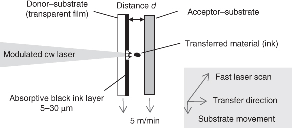
Figure 16.1 Scheme of Lasersonic® LIFT printing of black (absorptive) ink.
This scheme is in essence similar to a lot of other LIFT applications. However, the difference is that the laser beam can be scanned at ultrafast speeds (with 400 m/s up to 2116 m/s, depending on the operation mode) across the donor substrate in order to achieve an acceptable area throughput for the application. Additionally, the acceptor substrate can be moved with a speed of up to 5 m/min in a cross-scan direction in order to perform a reel-to-reel process, and the donor film must be continuously moved forward in order to provide a fresh ink layer for each printed spot. Currently, the maximum area production rate is 2.65 m2/min for 300 dpi (limited by the acceptor substrate movement) and 1.325 m2/min for 600 dpi screen resolution, according to the requirements considered earlier.
The distance d between the donor and the acceptor substrates must be large enough to avoid mechanical contact between the donor and the acceptor, especially, when both are moving, and as small as possible in order to receive a precise ink transfer and to avoid, for instance, excessive spreading of satellite droplets. Typical values for d in R2R printing are in the range of 0.3 mm < d < 0.6 mm.
A full-color print requires – apart from black – at least primary inks such as cyan, magenta, and yellow. Usually, if made up by standard pigments, these inks are not absorptive at the laser wavelength of 1070 nm, though exceptions may eventually be posed by certain types of blue phtalocyanine pigments. This means that a different approach for the Lasersonic® printing of near-infrared (NIR)-transparent colors is required. The solution, the LIBT process, is shown in Figure 16.2. The donor substrate is coated by an absorption material, which is able to efficiently convert photonic energy into heat, and the ink is applied on top of this converting layer. The laser beam propagates through the transparent ink layer and is absorbed at the surface of the absorption layer, which faces the ink. The absorbed energy heats up the ink at this interface zone and generates an explosively expanding vapor bubble, pushing the ink toward the acceptor. Due to the inverse direction of the laser, this process is named LIBT (laser-induced backward transfer). The scanning scheme of the laser beam and the substrate movement is analoguous to that shown in Figure 16.1. More details about the absorption layer are described in Section 16.5.4.
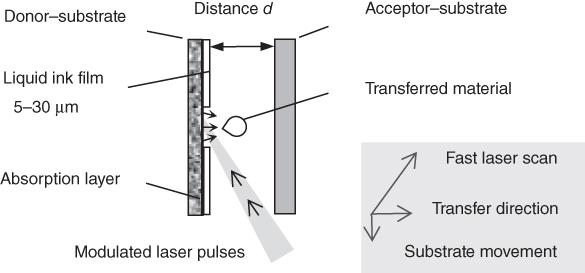
Figure 16.2 Lasersonic® LIBT printing of transparent inks.
In order to avoid blocking or shadowing of the incident laser beam by the acceptor substrate, the spatial arrangement of the color printing unit has been designed as shown in Figure 16.3. The laser beam hits the donor substrate surface with an angle of incidence of 60° referring to the normal direction. This is close to the Brewster angle of the fluidic ink layer, and an appropriately polarized laser beam shows only reduced reflection losses at the ink surface. The size of the laser focus is shaped elliptically at the scanline with a diameter of 30 µm in cross-scan direction and 60 µm in scan direction. For 60° of incidence, the projection on the surface of the donor roller results in a 60 µm round laser spot.

Figure 16.3 Printing unit for continuous R2R printing of color pigmented NIR-transparent inks; the ink roller is precoated with a laser-absorbing material.
The laser beam scans a 530 mm long line on the surface of the ink roller parallel to the roller axis with up to 2 kHz line frequency, and the substrate is synchronously moving in cross-scan direction. The ink roller is coated with ink by a precise inking system as described in Section 16.5.3.
16.4 Optical Concept and Pulse Control of the Lasersonic® Printing Machine
The optical beam path of the laser scan unit is shown in Figure 16.4. A high-power cw fiber laser beam with 300 W is modulated by an acousto-optical modulator (AOM), scanned by a fast rotating polygon mirror and focused by an f-theta lens system onto the scanline at the ink roller surface, respectively, at the absorption layer.

Figure 16.4 Optical laser beam path of the printing unit (one-color).
16.4.1 Ultrafast Pulse Modulation at High Power Level
For the described printing applications, a fast writing speed of at least 1.3 m2/min with 600 dpi pixel resolution is desired. That corresponds for a one-color printing unit to 1.5 gigapixel per minute and a high modulation rate of up to 25 MHz, which is very challenging at this high power range. For the Lasersonic® approach, acousto-optical modulation has been used because it turned out that a tailored AOM was less expensive and easier to push to high pulse rates than high-voltage-driven electro-optical modulation. With a cw-power of 300 W from the laser, an efficiency of more than 56% in the first diffracted order could be achieved at 25 MHz. The dynamical contrast ratio of the AOM is the ratio of the minimum to the maximum power signal of the first diffracted order when an on/off modulated input signal is applied. It was measured with a fast photodiode. The dynamical contrast ratio depends strongly on the modulation rate, if – in the high-frequency regime – the modulation rate is as fast as that permitted by the minimum rise and fall times of the AOM sound field. At 20 MHz, the measured contrast ratio has been 1 : 8 and enables for a dynamical modulation range of 87.5% of the laser peak power. The example illustrated in Figure 16.5 shows that the photodiode signal of the power in the first AOM order can be varied from 12.5% to 100% of the full signal (3–24 mV) by changing the input signal from 0% to 100%. This power modulation hub of 87.5% enables for an on/off pulse control of the LIFT process at each single pixel of the printed image. The residual power of 12.5% in the first diffracted order does not have any impact on the transfer because the value is below the process threshold of the LIFT process if the laser is scanned as fast as that described in Section 16.4.4.

Figure 16.5 (a) Laser power signal of first diffracted order at 20 MHz (AOM input signal is displayed at screen bottom), (b) frequency response of the dynamical range for on/off.
At a modulation rate of 25 MHz, the contrast ratio drops down to 1 : 5. This is equivalent to a modulation range of only 80%. Even this is sufficient to modulate the LIFT/LIBT process. The increased residual power of now 20% is again below the process threshold because the threshold power increases as well due to a shorter time of impact of the laser at higher frequency and higher scan speed. At lower frequencies, that is, at 5 MHz, the contrast ratio exceeds 1 : 25 according to a dynamical modulation range of 96% (Figure 16.5) with a residual power of only 4%. Therefore, the process steering by modulation works well over a large frequency range.
16.4.2 Time Schemes
The concept of the modulated cw-laser beam allows the application of various time schemes with variable pulse length and pulse height control.
The default scheme is the simple on/off switching of the RF power in order to generate separated pulses, as shown in Figure 16.5. The number of peaks/s represents the pulse rate or pixel rate. If using an AOM, the lower limit of a minimum pulse length is given by the sum of rise and fall times of the AOM sound field along the cross section of the laser beam. For example, for a sound velocity of 5 × 10³ m/s within the AOM crystal and for a laser beam diameter of 100 µm, a time of about 20 ns is needed for rise time and again for fall time of the RF field across the beam. Without plateau, the on/off time for the whole pulse sums up to about 40 ns, according to a maximum repetition rate of separated pulses of 25 MHz.
Another modulation scheme is the direct switching between subsequent power levels: The power level of the RF input signal is switched just from one value to the next value without intermediate zero level according to the change of the grayscale value from one pixel of an image to the next in the input data (Figure 16.6, PRF input signal). This suggests that a doubling of the data pixel rate of up to 50 MHz (20 ns per pixel) might be possible. However, the sound field that is induced by the RF signal in the AOM needs about 40 ns time to propagate across the laser beam cross section, so that the effective pulse energy that is irradiated to a pixel at the scanline becomes a mixture (a weighted sum) of the pulse energies of its correlated data pixel and neighbored data pixels (calculable by integration of Peff_laser over the exposure time). For a screen of 600 dpi with a pixel size of 42 µm and for a scan speed of 2100 m/s, the scan time across a pixel is only 20 ns (minimum exposure time). In that case, at least two data pixels contribute partly to the effective pulse energy impact at that pixel. The size of 60 µm of the laser focus at the scanline is still neglected in this model and leads to an additional elongation of the exposure time to 50 ns at 2100 m/s with partial contribution of four data pixels, which are differently weighted according to the changing spatial overlap of the laser spot and the pixel area during scanning. Therefore, the grayscale values of the printed dots become blurred and incorrect. We learn from Figure 16.6 that a crucial criterion for the printing speed is the switching speed of the power level of the laser beam by the modulator. The direct switching scheme is not well suited for acousto-optical modulation of a cw-laser due to the slow slope of the laser pulse. However, if a ps-laser or sub-ns laser is used and the RF field in the modulator is synchronized in such a way that it covers the whole laser beam cross section exactly at the time when the laser pulse appears, this scheme can be applied and power level values are correct. (Here the question remains, if the ps pulses does not destroy the modulator crystal.) In addition, in case of electro-optical modulation, which might be performed by high technical effort with faster rise and fall times of the resulting high power laser pulses than acousto-optical modulation (required are smaller than 1 ns rise and fall times), this time scheme might be an option to boost the data pixel rate up to 50 MHz without mixing of data pixel grayscale values.

Figure 16.6 Schematic diagram of direct switching between power levels. The RF input signal is switched each 20 ns according to the image data. The resulting laser pulses in the first diffracted order after the AOM need a rise time of 20 ns and a fall time of 20 ns (simplified shown as triangles with dashed lines). At the falling edge of these laser pulses, the next data pixel is already set and the next RF field has been started to propagate through the laser beam and already contributes to the effective laser power in the first diffracted order. The power curves of all pulses (dashed lines) are summed up to the effective laser power in the first diffracted order (bold curve).
Nevertheless, this kind of modulation scheme is helpful in order to study the mechanism and limits of correct pixel reproduction. For example, it can be used for the investigation of the transfer process of the ink, especially in case of drawing a line in the scan direction with a constant power level all over the line without intermediate zero level. In Section 16.7, how the LIFT transfer process is being affected by the modulation time schemes is described.
16.4.3 Data Flow
Data sources in printing are typically files such as bitmaps or tiff files, which provide an 8-bit or 12-bit grayscale value for each pixel of an image. The data output has to be synchronized along the scanline according to the master clock pulses of the polygon encoder and corrected for facet angle errors or other discontinuities in scan direction. The data output scheme must be edited and recalculated according to the correct timing information, for instance, for the purpose of introducing adopted time delays for each facet in the case of a nonideal polygon, defining starting points and compensating flatness deviations of the facets (convexity) by rescaling the scanline length in order to finally determine the correct pixel positions at the donor substrate. At a data rate of 20 MHz to 25 MHz, this requires fast FPGA processors with reference clock rates of up to some hundred MHz. After calculation (and digital–analog conversion), the data are sent sequentially to the AOM driver electronics.
16.4.4 Ultrafast Scan of the Laser Beam
As described in Section 16.2.2, the market aims for a productive printing speed of at least several m2/min, even at a screen resolution of 600 dpi. This can be satisfied only with a beam scanning strategy, which allows for a scan speed of more than 1000 m/s over the whole scanline.
Therefore, the scanning unit was designed based on a fast spinning polygon wheel and a new concept for an f-theta lens unit. A solution for the correction of polygon errors as pyramidal error and facet-to-facet angle tolerances is commonly obtained by additional galvoscanner mirrors. However, at the high line frequency of 1–2 kHz, this is no more possible in a satisfactory precise manner. In order to minimize the impact of pyramidal errors of the polygon facets onto distance variations of subsequent scanlines on the donor substrate, an anamorphic optical system with cylindrical lenses was designed, which allows to separate the propagation properties of the laser beam in two independent (orthogonal) components, one in the horizontal-scan direction (x-axis) and the other in the vertical cross-scan direction (y-axis). The laser beam has been transformed by cylindrical lenses in such a way that at a certain z-position the x component of the laser beam is in the far field with respect to the scanline and the y component is at the same z-position in the near field with respect to the scanline (Figure 16.7). If the polygon facet is placed at this z-position, both laser beam components behave in different ways: for the far-field component, a change of the angle of the polygon facet (as during rotation or also due to polygon shape errors) leads to a change of the focus position along the scanline. Fabrication tolerances of the polygon facet angle from facet to facet in the scan direction can be corrected by appropriate time delays of the modulation signal, which generates the laser pulses at each new scanline.
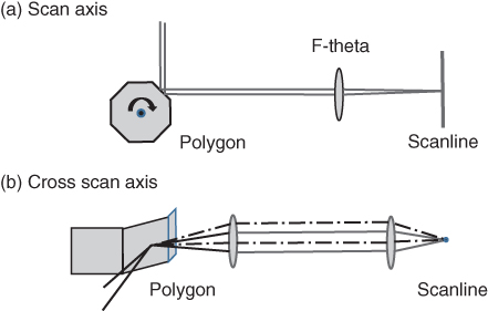
Figure 16.7 Purpose of anamorphic optics: (a) scan direction with far field at polygon surface, (b) cross-scan direction with near field at polygon surface, insensitive against pyramidal error; if the polygon facet is slightly tilted, the beam follows the dashed line, but the focus point stays stable at the scanline.
On the other hand, for the near-field component, the focus position on the substrate in cross-scan direction is insensitive to variations of the polygon facet angle in the y-direction, and the focus position remains stable on the donor substrate. This is a passive stabilization of the focus position in the cross-scan direction and a passive suppression of the pyramidal error of the polygon. However, this has strong consequences for the design of the f-theta unit, which must be built up as an anamorphic lens system as well. On the other hand, this concept opens the way for different focus spot sizes in scan and cross-scan directions, especially, to achieve a 2w0-spot size of only 30 µm in the cross-scan direction and of 60 µm in the scan direction. This was very helpful to realize the 60° angle of incidence and to achieve at the same time a round projection of the spot with 60 µm diameter on the absorption layer, as described in Section 16.3.1. We achieved a scan speed of more than 2000 m/s over a scanline length of 530 mm and with a pixel-to-pixel distance of 84 µm (300 dpi). The alignment of the components of this anamorphic optical beam path has to be carried out very accurately using tools such as autocollimator and Shack–Hartmann wavefront sensor. The duty cycle of a polygon is the percentage of the revolution time that can be used effectively for the scan of the beam. During transit time, when the extended diameter of the laser beam crosses one of the edges of the polygon, the laser beam must be interrupted. Usually, the laser energy is wasted during this time. To continuously use nearly the whole power delivered by one laser source, we switched the laser beam between two different printing units on opposite sides of a two-color double print unit. This works as follows (see Figure 16.8): the duty cycle of the polygon was chosen closely below 50%. As long as the beam from the right side hits on top of a facet of the rotating polygon, the right printing unit is scanned by this beam. However, just before the beam starts to run over the edge from one facet to the other, the beam path is switched to hit the polygon from its other side (again on a facet) in order to serve the left printing unit. By this method, only one laser source and one polygon are needed to generate two timely alternating scanlines, each with a line frequency of up to 2 kHz and a scan length of 530 mm.

Figure 16.8 Two-color double-printing unit for transparent inks. The laser beam alternates between left and right scanline.
16.5 The Four-Color Lasersonic® Printing Machine
16.5.1 Large-Area, High-Throughput LIFT/LIBT Inline R2R Printing System
The four-color Lasersonic printing machine is built up as a combination of two two-color double print units as shown in Figure 16.9. The combination concept is scalable to three or four double print units for printing with six or eight colors. The substrate passes the four printing units one after the other with intermediate ink drying devices and automated corrections of path deviations (web guide control). Some features of the substrate guiding system are shown in Table 16.1.

Figure 16.9 Four-color Lasersonic® printing machine with unwinder and rewinder unit of the substrate, ink mixing and supply tanks, printing units, and human interfaces. The inking modules on top can be exchanged within a few minutes to vary between different inks or ink sequences.
Table 16.1 Web characteristics
| Parameter | Range |
| Maximum web size | 630 mm |
| Web speed (synchronized with polygon scan) | 0–5 m/s |
| Gap width between ink roller and paper | 0–1.5 mm |
| Maximum print width | 530 mm |
| Maximum paper reel diameter | 1000 mm |
| Maximum paper reel weight | 500 kg |
Multicolor printing with several printing units requires a precise synchronization between the time-dependent local position of the fast scanned laser beams on each scanline, the x-, z-feed position of the substrate at each printing unit and the exact timing of each AOM signal for the laser modulation based on the data flow.
For this purpose, the angular position of the fast rotating polygon – which represents the laser spot position at the scanline – is detected by a rotary encoder at each double-print unit. The clock signal of the encoder is used as a master trigger of the unit. Steering signals, which are synchronized to this master, regulate the feedforward of the substrate and control the image data output processing for the laser power modulation with the AOM. The laser beam position, the transversal and longitudinal control of the correct substrate movement, and the start position of the scanline are essentially “to be matched” parameters. Multiple control systems and more than 50 motor-driven axes are involved. Moreover, the mixture and viscosity of the ink can be actively adjusted to optimize the conditions for the LIFT process.
16.5.2 Printing Heads for Absorptive (Black) and for Transparent (Colored) Inks
As mentioned in Section 16.3.1, two technical approaches for the donor substrate have been realized, an circulating transparent endless ribbon for the black ink printing unit and an ink roller, coated by an absorption layer, for each of the color printing units.
The design of a machine for industrial use should be based as much as possible on the integration of identical components or modules, especially if these are highly performing parts, which require major efforts in development. The optical system for the creation of the 530 mm long scanline is such a module. In order to avoid the development of two different scan modules, the same one should be used for the black ink printing unit and for the color printing units. In both cases, a passive cross-scan correction is helpful to ensure equal distances from scanline to scanline, especially at high scan speeds when galvomirror correction of the pyramidal error is not fast enough. Hence, the f-theta unit is designed as an anamorphic system (Figure 16.7). Moreover, in case of the LIBT color printing unit, an angle of incidence of the laser beam on the ink roller of 60° is used in order to avoid collision with the paper. The anamorphic approach allows not only the passive cross-scan correction but also to generate an elliptical focus spot at the scanline of the f-theta unit (60 µm spot diameter in scan direction, 30 µm in cross-scan direction) in order to finally achieve a round projection of this elliptical focus on the ink roller. When using the same f-theta module, the same projection should also be applied to the printing unit for absorbing (black) ink. Therefore, the donor ribbon is arranged under 60° instead of being perpendicular to the laser beam. An additional advantage is that the beam is coupled near the Brewster angle through the donor ribbon. It is a challenge to handle a 530 mm wide flexible donor ribbon and to ensure equal ink layer thickness and density over the whole width. In order to make this easier, the donor ribbon is designed much smaller than the scanline length, but the feeding direction is under an angle of only less than 10° to the scanline instead of 90°. By this, the whole scanline can be covered by a narrower donor substrate with a width less than 100 mm. Figure 16.10 shows a scheme of the print unit for absorbing inks. The feed rate of the donor ribbon has to be fast enough to provide a complete fresh ink layer for the next scanline.

Figure 16.10 Print unit for absorbing ink, the scanline is covered over the whole length by the donor ribbon, the laser comes from the backside, hits the ribbon under 60°, and is scanned along the scanline.
The geometry of the color printing unit has already been explained in Section 16.3.1 and by means of Figure 16.3. The unit is shown in Figure 16.11 in raised position for maintenance in order to allow a view to the ink roller and the substrate. In operation mode, the ink roller and the substrate are closer to each other with a gap in the range of 0.3–0.6 mm.

Figure 16.11 Printing unit for transparent inks lifted up for maintenance; in operation, the ink roller is positioned about 0.5 mm close to the substrate.
16.5.3 Inking Units
Both of the described printing head types include an appropriate inking unit, a roller inking unit for the IR-transparent inks (Figure 16.12), and a ribbon inking unit for the IR-absorptive inks (Figure 16.13). The machine concept contains the flexibility to use each inking unit module on each one of the four scanline positions in order to vary between different inks or color sequences (Figure 16.9). The quality and function of the LIFT/LIBT printing units are highly dependent on a uniform and homogeneous ink layer on the donor surface of the converting roller or of the ribbon along the scanline. The most important design approach for both kinds of ink coating systems is the capability to generate a precisely defined, homogeneous, and isotropic thin ink layer at the printing zone.

Figure 16.12 Roller inking unit for NIR-transparent inks.
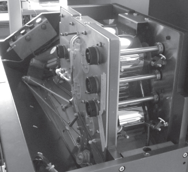
Figure 16.13 Ribbon inking unit for NIR-absorptive inks.
There are several different kinds of classical inking concepts, each of them in use for industrial processes. For the ink transport toward the printing zone, a conventional “4/5 roller system” has been selected. In this concept, the first two rollers are acting as pond rollers with a small, thin adjustable gap for predosing and preforming the ink layer and ink volume (Figure 16.12). The third roller is equalizing the ink layer and is the handover roller for either the LIBT roller or the LIFT ribbon (Figure 16.3).
The machine requires quite thin ink layers (5–30 µm thick). An ink thickness deviation of even 1 µm or little more on the circumference of the inking roller or on the ink ribbon could already lead to a color density deviation on the printed substrate, which might be detected by the human eye. This indicates the challenge presented to the mechanical engineering, parts manufacturing, and assembling. To have the chance to adjust to different rheological ink behavior in the inking unit, a high level of flexibility in roller gap distances, drive speeds of the rollers, rotating directions, and ink flow volume was incorporated in the engineering and operating concept. Evidence of an imperfect ink distribution on the roller or ribbon surface are stripes, rings, clouds, and all other visible structures. Any anisotropic appearance of the ink on the surface of the carrier roller or ribbon would lead to unacceptable quality defects in the visual appearance of the final print. Summing up all the factors of physical, mechanical, or chemical origin, which influence the even ink laydown, is beyond the scope of this chapter. One major factor is the ink's complex viscosity, which takes into consideration the dynamical physical effects caused by changing shear rates during ink transport within the inking unit, that is, shear thinning effects in non-Newtonian fluids also named structural viscosity effects. As temperature and solvent content are major factors that influence the ink viscosity, the described machine and its inking units are equipped with viscosity sensors and were designed to operate with an automatic viscosity control system. According to the results and experience gathered during the trials and process development with the machine, each different kind of ink or liquid to be printed or transferred by this machine requires its individual and specific set of operating parameters in the inking unit. This has to be taken into account for future concepts of LIFT/LIBT printing units, which will be designed for more than one single type of ink or material suspension.
16.5.4 Synthetic Approaches to the Absorption Layer of the LIBT Donor Surface
In the course of prior experiments, the absorption layer of the donor roller was realized by use of various types and qualities of carbon black as absorbing agents. The carbon black pigments were dispersed in heat-resistant matrices and afterward used to cover the donor. However, these layers were rapidly worn out by the mechanical stresses as exerted by sudden and steep local temperature changes and by cavitation erosion caused by the collapses of jet driving vapor bubbles. Service life has been restricted to several hours of operation only, and the rollers had to be exchanged after that. More wear-resistant converter layers with considerably prolonged service life have been designed by synthesizing highly efficient organic NIR absorbers, which – after dispersing them into high-temperature-withstanding silicon resins – have been equally spread as an even and isotropic layer over the cylindrical surface of the converter roller. Afterward, this coating was burned at a temperature of 120 °C over a period of 4 h in a homogeneously air-vented oven.
16.6 Print Experiments and Results
In order to study the LIFT/LIBT transfer process in the regime of high pulse repetition rates and at high scan speeds and in order to demonstrate the functionality of the print unit concept, the first printing experiments were run with one print unit (one color) only. During these tests, various customary paper webs and foil substrates as well as different ink materials were evaluated. The range of process parameters of the machine and the ones regarded as most practical are listed in Table 16.2. Some of these parameters (such as the laser power, web tension, web speed, ink viscosity) could be varied and controlled directly during the running print process and have been optimized for every ink–substrate combination by on-the-fly reference to print results.
Table 16.2 Parameter ranges of the machine and of used consumables
| Parameter | Range | Mainly used setting (best results) |
| Area screen resolution | 300–600 dpi | 600 dpi |
| Laser power (pulse peak) | 0–154 W | Gray scale value dependent |
| Pulse repetition rate PRR | 5–25 MHz | 23.6 MHz |
| Pulse width (FWHM) | 16 ns to several microseconds | 16 ns |
| Scan speed laser focus | 400–2116 m/s | 1000 m/s |
| Line frequency | 0.5–2 kHz | 0.943 kHz |
| Web speed | 0–5 m/s | 2.4 m/s |
| Gap donor roller/substrate | 0–1500 µm | 350–600 µm |
| Web tension paper | 0–300 N | 50–150 N (300 µm) |
| Web tension thin foils | 0–300 N | 30–70 N |
| Sort of ink (water-based) | Rotogravure décor ink with organic pigments and casein binders or with pearlescent pigments and casein binders | 8 < Visc < 20 mPa s Ink pigment size 5–100 µm |
| Sort of Ink (solvent-based) | PVB ink, CN ink | 8 < Visc < 20 mPa s |
| Types of substrate/thickness | Décor paper LWC paper OPP film, PE film |
60 µm 70 µm 90, 50 µm |
They have been measured in real time and displayed at the monitor. Viscosity readings were taken with a 3 mm Frickmar-efflux cup at 20 °C and have been converted to dynamical viscosity. Automated viscosity control was performed with a vibrating rod device. The print results show that the LIFT/LIBT process with an acousto-optical-modulated cw-laser beam is well suited to transfer inks with different pigment sizes, attributes, and features such as habitus, coatings, and organic/inorganic nature. Tests have been run with highly scattering TiO2 pigmented inks as well as inks with large and flaky pigment sizes of the leaving and nonleaving type for metallic or mother-of-pearl effect as well as trials with various types of widespread, standard pigmented inks used in bulk quantities all over the gravure- and flexo-, décor- and packaging-printing industries worldwide. Most prominent among the standard inks for decor and packaging applications are water-dilutable decor inks based on casein as binding system, alcohol- or ester-based CN inks for packaging with various types of cellulose nitrate binders as well as polyvinyl butyral (PVB) inks for packaging, which are diluted with organic solvents as well (Figures 16.14 and 16.15).

Figure 16.14 Test print example with PVB ink on OPP film, web size 630 mm, width of printed area 435 mm, length 730 mm, resolution 600 dpi, feeding speed 2.39 m/min, scan speed 1000 m/s, printing time 18 s for the complete sheet.
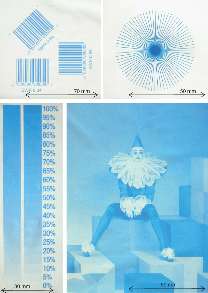
Figure 16.15 Details of the print example of Figure 16.14: bar codes with various orientations, line stars for resolution proof, continuous and stepped grayscales and a grayscale test image (600 dpi).
All these inks may be tinted with both organic or inorganic pigments. Undesired side effects of the LIFT/LIBT process, affecting the quality of the print, have been observed, such as satellite drops sputtered on the substrate or haze and fog of the ink along the scanline, reappearing on the substrate and also drifting backward into the optics compartment. Parts of the haze condensation may have electrostatic origin. Whiskers due to electrostatic discharge may be occasionally discerned on the print. The charge-generating mechanism of the LIBT/LIFT elementary drop-generating process seems to be quite prone to parasitic charge accumulation by a very sudden material separation and hence depending on the material's work functions. CN-ink systems showed slightly more of these unwanted side effects (clouds of haze and whiskers) compared to the other inks.
To at least partly avoid these electrostatic effects, different additives were tested with moderate success.
Other types of additives to improve the rheology of the inks, thereby preventing the generation of satellite drops, were tried with considerable success. Further reduction of satellites, haze, and fog has been achieved by reducing the laser power to a level just above the process threshold. With all the aforementioned additions to and slight alterations of the base inks, the general principle was strictly observed, not to bring a new and special ink into play, but instead rely on the standard range of commonly used additives in common printing business with the aforementioned types of inks.
The best LIFT/LIBT results were realized with polyvinyl butyral (PVB) inks on OPP foil, when using drying-time-retarding additives and solvents. Optical densities of the printouts have been achieved as required for the printing industry (i.e., OD > 1.95 for magenta, OD > 2.5 for cyan). The distance between the ink roller and the substrate should be as small as possible in order to achieve optimized transfer results. For the test results shown in Figures 16.14 and 16.15, this distance was fixed at 0.5 mm, thereby leaving enough space between the ink roller and the running web to avoid any contact. The feed rate of the substrate was 2.39 m/min, the scan speed was 1000 m/s, and the modulation rate was 23.6 MHz.
A closer insight into the LIFT transfer process with modulated cw laser can be gained by analyzing the printing of lines along the scan direction. The fast modulation method of the high-power cw-laser beam allows the application of various time schemes in order to understand and optimize the LIFT/LIBT process. The question is, how to write a line in the scan direction with best precision and reproducibility of the image data input. Figure 16.16 shows several scanlines, one below the other. Dots printed by short modulated single pulses (t = 42 ns and t = 84 ns) occur for each scan at the same position of the scanline. This means their position is controllable. The length of the single pulses defines the amount of ink volume that is transferred by the droplet. The 84 ns long pulses generate dots with a larger diameter (dot size <100 µm) than the 42 ns long pulses (dot size <50 µm). The entire volume of ink transferred by these single pulses is collected in a single dot. Fine structures must be printed with short pulses.
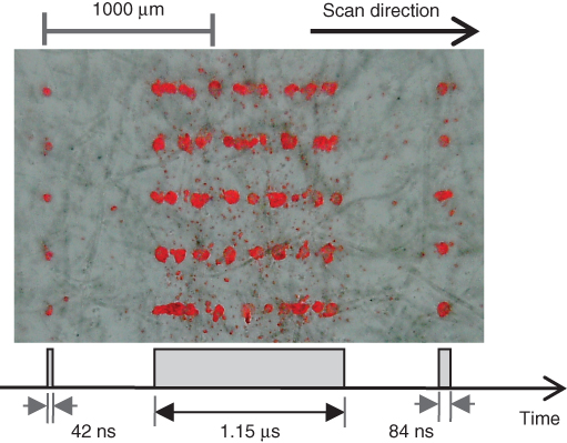
Figure 16.16 Effects of different durations of “laser on” periods: long “laser on” periods over some microseconds show uncontrollable separation of droplets; for single shots in the ns range, the dot size increases with the pulse length. The on-level of the AOM input signal was of equal height for all pulse lengths and ”laser on” periods.
For long “laser on periods,” the dots are randomly distributed along the scanline with the exception of the first dots of the long periods, which are aligned accordingly to the rising edge of the “laser on period.” This disruptive behavior along the lines shows that the ink transfer is not simply correlated to the time pattern of the laser impact but is influenced by fluid dynamics and the dynamics of heat dissipation on the converter surface as well. As described in Section 16.7, the correct alignment and positioning of the transferred LIFT dots and the correct and precise reproduction of the grayscale values of an image require the development of appropriate modulation and timing algorithms for the laser beam, which must refer to the detailed physics of the elementary processes behind the transfer.
16.7 Discussion of Effects
16.7.1 LIFT Process with Continuous-Wave Laser Source and Fast Modulation
To understand and control the LIFT transfer process with a fast scanned and modulated cw-laser focus, we have to take into account the following aspects:
- 1. Due to the fast scan velocity of the laser beam within the range of 1000–2000 m/s, even a not pulse-modulated cw-laser beam has locally (at one point of the scanline) only a timely short impact resulting in a “single quasi laser pulse” at this point. The transient field of the fast-passing laser gives a pulsed energy input to the absorption layer where the pulse duration τ is approximately given by the speed and the diameter of the laser spot (i.e., τ = 60 ns at 1000 m/s for a 60 µm spot size).
- 2. The timescale for excitation and energy impact is in the ns regime, whereas the transfer process itself, that is, the bubble and jet formation, takes 1–100 µs [3, 4]. On the timescale of the jet formation and transfer process, the energy impact to neighboring, closely spaced pixels along the scanline is done quasi simultaneously by the fast scanning laser beam. At a scan speed of 1000 m/s and with a screen resolution of 600 dpi (42 µm screen pitch), a line section of about 24 pixels can be activated per 1 µs.
- 3. In our case, the screen resolution is defined and limited by the achieved local precision of the power modulation of the scanned laser focus at a given scan velocity, that is, at v = 1000 m/s. Due to the fast acousto-optical modulation (see Section 16.3.1), we are able to control the positioning of the center of single dots with a screen resolution of 600 dpi (42 µm screen pitch for addressability of single pixels). The spot size of the laser beam (60 µm) and also the diameter of the printed dot may be even larger than 42 µm because in printing, an overlap of the dots is allowed, and for full-color applications, it is even necessary to avoid white, uncovered areas. The diameter of a printed dot depends mainly on the volume of the transferred ink and not directly on the screen resolution. The ink layer thickness on the ink roller has an important influence on the dot diameter.
In order to write continuous lines in the scan direction, tests were conducted to do this by writing with a “continuous laser on” mode by setting the laser modulation gray level permanently on a value above the threshold for the LIFT process (Figure 16.17). However, the resulting bubble formation and the ink transfer are not as continuous as the laser beam, but show droplets and interruptions, which lead to an irregular pattern of separated dots along this line. This separation into droplets must be investigated by numerical modeling of the interaction between shock wave forces during bubble expansion and tension forces of the ink during bubble collapse (see Chapters 4 and 5). As a first approach to an explanation, we assume that the different timescales of the fast excitation by the laser (60 ns) and the slow transfer process (1 – 100 µs) result in a quasi-simultaneous start of the bubble formation over many pixels along the scanned line. Over a line section of a few mm, the ink is transferred quasi simultaneously. Tension forces inside of the flowing ink lead to a separation into single droplets of various sizes during bubble formation and collapse and during the transfer process between the ink roller and the substrate. The separations do not occur periodically along the scan direction, but rather randomly with a large spatial jitter (Figure 16.17, left side). Important parameters for this effect are the viscosity and rheology (elastic forces, creep compliance) of the ink, the scanning speed, the laser beam intensity, and the distance d between the donor and the acceptor. During this process, it is likely that not only the ink region, which is directly excited by the laser, is pushed away, but also, due to tension and elastic forces, ink from the surrounding area is taken off and contributes to a droplet.
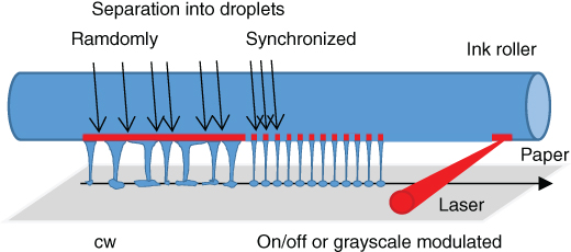
Figure 16.17 Line writing in scan direction with cw-“laser-on” mode compared to an on/off-modulated laser. At cw mode, an ink-layer stripe of a few millimeters length is quasi simultaneously transferred and separates due to tension forces of the ink randomly into droplets of various sizes. On/off modulation of the laser synchronizes the droplet separation with the pixel screen along the scanline.
To eliminate this random behavior of the droplet formation, an active on/off switching as well as power level grayscale modulation of the laser beam was investigated. The modulation signal was synchronized to the local position of the laser spot along the scanline (Figure 16.17, right side). The results show evidence that it is possible to realign the starting point of the droplet evolution by switching the laser beam off and on again in order to introduce controlled separations for the droplet formation while moving along the scan direction. For example, instead of line writing in scan direction with continuous “laser on” and with randomly droplet separation and irregular dots as shown in Figure 16.18, scanning with a “1-pixel on / 2-pixel off “- pattern leads to the periodical dot patterns of Figure 16.19. Due to the off time, less overall ink volume is transferred and the dot diameters (about 50 µm) are smaller than those shown in Figure 16.18. In addition, less satellite drops are generated between the lines.
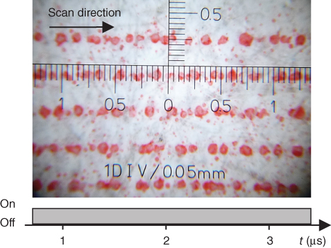
Figure 16.18 Line writing in scan direction with continuous “laser on” and v = 1000 m/s shows irregular patterns of dots along the scanline; a lot of small satellite drops are seen between the lines.

Figure 16.19 Pulsed laser operation leads to reproducible, separated single dots at defined position according to the screen, for example, line writing in scan direction with an one-pixel on/two-pixel off modulation shows regular patterns of dots.
16.7.2 Special Test Pattern to Study the Transfer Behavior at High Pixel Rate
To learn more about the conditions of the separation process, we tried to find out:
- 1. how long the laser pulse length may be at maximum, so that the whole ink volume of the corresponding laser excited line section is still flowing into only one single-transfer filament and one round spot;
- 2. when the spot starts to become elliptical;
- 3. when it will split into several dots.
As shown in Figure 16.20, a special data file (bitmap) was created, containing the following test pattern, which was repeated for statistic reasons each 30 pixels along the scanline: after a line with only a single “on pixel” (position marker function) and a few void lines for distance a line with 2 “on pixels” follows. After a gap, again a line with 1 “on pixel” (next position marker) and then a line with 3 on pixels was written.This scheme of alternating 1 “marker pixel” and n “on pixel” (n = 2, …, 20) was continued up to n = 20 and allows to detect the following effects (under the geometrical conditions and with scan parameters of this experiment):
- 1. The printed single-pixel dots follow exactly the vertical line a) and represent a feasible marker line of the scan position.
- 2. For the printed line segments with n < 8, the transferred ink was collected in only one jet, resulting in one printed dot with increasing diameter according to the number of excited pixels and with linearly shifted position. The position of this dot is nearly exactly at the center of mass of each excited “laser on” line segment, in Figure 16.20 indicated by line (b). The shape of the dot remains still round.
- 3. For 8 ≤ n ≤ 11, the printed dots become more and more elliptical. The homogeneity of the elliptical dots suggests that there is still only one common transfer jet collecting the ink of the whole line segment. The position is still at the center of mass of the bitmap line.
- 4. For n ≥ 12, the printed dots start to form two and (for higher n) also more subspots (nuclei) along the scanline, probably due to the evolution of more than one transfer jet. These subspots have different sizes and are irregularly positioned along the line segment. For longer line segments, they separate into several nuclei. These experiments have been done with a scan speed of 1000 m/s, at 23.6 MHz. Other scan parameters and ink properties may lead to different bubble and jet formations and to other numbers of combined pixels. It would be helpful to study the transfer process by shadowgraphy directly on the machine in order to confirm these observations, but the scanline region is not accessible for such equipment.
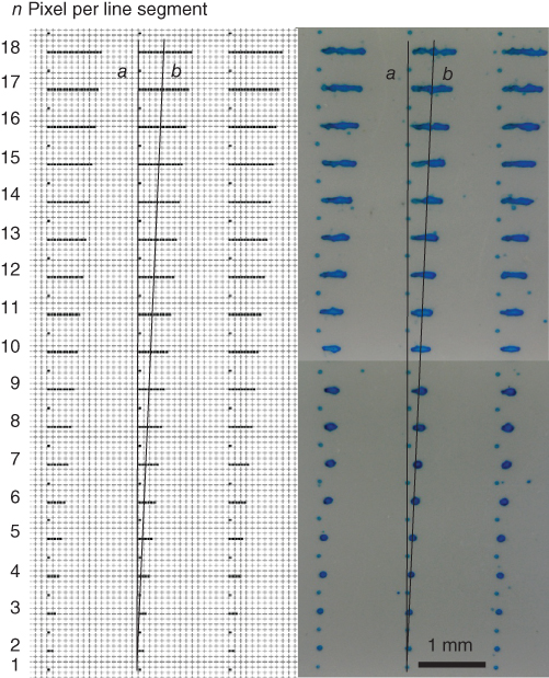
Figure 16.20 Test bitmap with increasing “on-pixel” line sections (left side) and print results (right side).
However, for the case n = 2, similar experiments have been performed by Patrascioiu et al. at the University of Barcelona ([24] and Chapter 4). These experiments focused on the jet evolution and interactions during the LIFT transfer of a fluidic material with low viscosity in case of simultaneous excitation by two laser spots, which have been positioned on the donor substrate with only a short distance to each other. Shadowgraphs show the timely development of bubbles and transfer jets for different laser spot distances. The key result is that only one jet is created and only one dot is printed just at the position in the middle between the two laser spots (the center of mass), when their distance is small enough. This is consistent with the print result in Figure 16.20.
For an accurate reproduction of the image data, these jetting effects must be eliminated. The obvious way to avoid coalescence of several pixels is to print with spatially enough separated pulses. If the distance of two consecutive ”laser on spots” is large enough, no interaction between the separately excited jets is observed and the print results show regular dots. This is the case for, for example, the “1 pixel on – 2 pixel off” pattern along the scanline, as already shown in Figure 16.19. In order to fill the gaps without jet interactions, the pixels between the on-pixels should be printed with enough timely separation, for example, in a second and a third scan process making multiple passes with the same laser beam or using simultaneously a multispot arrangement with enough distance of the spots.
16.8 Future Directions
LIFT/LIBT solutions in graphical art applications may find their niche in the current trends to functionalize printing products. Major trends driven by market demands are applications such as smart labels and packaging solutions with integrated functions. In particular, the fabrication of printed organic electronics may open additional opportunities. Still there is a tough competition between the different fabrication methods, traditional and advanced ones, to establish themselves as major production techniques in those emerging product segments. Associations such as the OE-A (Organic and Printed Electronics Association) offer platforms [25] to learn about markets, requirements, and solutions. In the classical graphical art markets, digital printing techniques are entering more and more markets such as label printing or packaging printing. Still many of the special requirements of those applications are not suitably solved by the current digital printing techniques, for example, printing of pearlescent or metallic pigments with particle sizes of 2–100 µm. Here still indirect solutions such as hybrid production techniques with digital printing and conventional or semidigital transferring techniques for pearlescent or metallic printing are state of the art. As the “pain” of the unresolved customer requirements regarding digital printing of special inks is going on and additional requirements regarding functionalization of printed products are rising, this may open new opportunities to implement LIFT/LIBT solutions in the form of special printing units for fully digital hybrid production environments.
16.9 Summary
The Lasersonic® LIFT/LIBT process is suited to be used for fast, large-area direct-writing processes in industrial applications such as commercial digital printing. The physical properties of the laser-induced transfer process open new digital printing features, which are difficult to realize by other digital printing methods such as inkjet or Xerography. High area throughput can be achieved by using a high-power cw-laser beam, which is scanned at high speed (>1000 m/s) over the substrate. A fast modulation of this beam with a data rate of 20–25 MHz allows even at this speed for screen resolutions of 600 dpi. Large-area printing up to 2.6 m2/min was demonstrated with common liquid inks on different common substrates. Inks with small (<1 µm) and large (100 µm) pigments could be transferred by this fast LIFT/LIBT process. The investigation of dynamic effects during the transfer of such liquid materials at high scan rates with simultaneous excitation of many pixels leads to a new understanding of how to operate the machine. Appropriate modulation time schemes such as the “1 pixel on – 2 pixel off scheme” with multiple passes are suited to achieve high-quality printing results. LIFT/LIBT solutions in printing applications may find their niche in the current trends to functionalize printing products and may be used to promote applications such as smart labels, packaging solutions with integrated functions and new upcoming function requirements on printing products.
Acknowledgments
The authors give special thanks to the project team of the DI Project AG, namely Peter Daetwyler, René Hartmann, Rudolf Griebel, Christian Nussbaum, Marcel Rossier, Andreas Brockelt, and Lorenz Schuler, for their restless work, precious contributions, ideas, and their commitment for this Digital Imaging project. Also special thanks go to Craig Arnold, Princeton University, Pere Serra, University of Barcelona, and Philippe Delaporte, Marseille University, for many discussions on the dynamics of the liquid ink transfer.
References
- 1 Young, D., Auyeung, R.C.Y., Piqué, A., Chrisey, D.B., and Dlott, D.D. (2001) Time-resolved optical microscopy of a laser-based forward transfer process. Appl. Phys. Lett., 78 (21), 3169–3171.
- 2 Young, D., Auyeung, R.C.Y., Piqué, A., Chrisey, D.B., and Dlott, D.D. (2002) Plume and jetting regimes in a laser based forward transfer process as observed by time-resolved optical microscopy. Appl. Surf. Sci., 197, 181–187.
- 3 Brown, M.S., Kattamis, N.T., and Arnold, C.B. (2011) Time-resolved dynamics of laser induced microjets from thin liquid films. Microfluid. Nanofluid., 11, 199–207.
- 4 Duocastella, M., Fernandez-Pradas, J., Morenza, J., and Serra, P. (2009) Time-resolved imaging of the laser forward transfer of liquids. J. Appl. Phys., 106 (8), 084907.
- 5 Duocastella, M., Fernandez-Pradas, J., Serra, P., and Morenza, J. (2008) Jet formation in the laser forward transfer of liquids. Appl Phys A, 93 (2), 453–456.
- 6 Minsier, V., De Wilde, J., and Proost, J. (2009) Simulation of the effect of viscosity on jet penetration into a single cavitating bubble. J. Appl. Phys., 106 (8), 084906.
- 7 Colina, M., Duocastella, M., Fernandez-Pradas, J., Serra, P., and Morenza, J. (2006) Laser induced forward transfer of liquids: study of the droplet ejection process. J. Appl. Phys., 99 (8), 084909.
- 8 Serra, P., Duocastella, M., Fernández-Pradas, J., and Morenza, J. (2009) Liquids microprinting through laser-induced forward transfer. Appl. Surf. Sci., 255, 5342–5345.
- 9 Duocastella, M., Fernández-Pradas, J., Morenza, J., and Serra, P. (2010) Sessile droplet formation in the laser-induced forward transfer of liquids: a time-resolved imaging study. Thin Solid Films, 518, 5321–5325.
- 10 Unger, C., Gruene, M., Koch, L., Koch, J., and Chichkov, B. (2011) Time-resolved imaging of hydrogel printing via laser-induced forward transfer. Appl. Phys. A, 103, 271–277.
- 11 Browning, I. and Johnson, P. (1974) Recording method and apparatus utilizing light energy to move record forming material onto a record medium. US Patent 3.798.365, filed July, 14, 1969, granted March 19, 1974.
- 12 Kohyama, M. (1991) Laser actuated recording apparatus. US Patent 5.021.808, filed 1989, granted 1991.
- 13 Maximovski, S. and Radutzki, G. (2000) Method of ink-jet printing and an ink-jet printing head for carrying out the method. US Patent 6.056.388, filed 1995, granted 2000.
- 14 Maximovski, S. and Radutzki, G. (2001) Printing method and printing device for realizing the same. US Patent 6.270.194 B1, filed 1997, granted 2001.
- 15 Lehmann, U. and Meyer, D. (2006) Aurentum GmbH. US Patent 7.154.522 B2.
- 16 Lehmann, U. (1999) Aurentum GmbH, Druckverfahren und Einrichtung zu dessen Durchführung. DE Patent 19746174 C1.
- 17 Lehmann, U. (2003) Aurentum GmbH, Method of printing and corresponding print machine. US Patent 2003/0156178.
- 18 Ferchner, H.G., Gerner, H., and Lehmann, U. (2006) Aurentum Innovationstechnologien GmbH: Digitale Druck und Strukturierungsverfahren. 18th Workshop “Mikrotechnische Produktion - ProPolyTec – Produktionstechnik für die Polymerelektronik”, Fürth 2006, published in “Abschlussbericht BMBF Project ProPolyTech”, editor G. Klink, Fraunhofer IZM, Munich, p. 103.
- 19 Hennig, G., Baldermann, T., Nussbaum, C., Rossier, M., Brockelt, A., Schuler, L., and Hochstein, G. (2012) Lasersonic® LIFT process for large area digital printing. J. Laser Micro/Nanoeng., 7 (3), 299–305.
- 20 Homepage Durst Phototechnik AG http://www.durst.it/index.php/durst/article/digital-decoration-die-stille-revolution (accessed 25 October 2016).
- 21 http://eur-lex.europa.eu/legal-content/EN/ALL/?uri=CELEX%3A32011R0010 (accessed 25 October 2016).
- 22 http://ec.europa.eu/growth/tools-databases/tris/de/search/?trisaction=search.detail&year=2016&num=333 (accessed 25 October 2016).
- 23 https://www.gesetze-im-internet.de/bundesrecht/bedggstv/gesamt.pdf (accessed 25 October 2016).
- 24 Patrascioiu, A., Florian, C., Fernández-Pradas, J.M., Morenza, J.L., Hennig, G., Delaporte, P., and Serra, P. (2014) Interaction between jets during laser-induced forward transfer. Appl. Phys. Lett., 105 (014101).
- 25 Homepage Organic and Printed Electronics Association http://www.oe-a.org/home (accessed 25 October 2016).