
3
Meet the Circuit
In the last chapter, you learned a bit about the Arduino and its parts. You were also introduced to some of the components and tools you’ll be using to complete the projects in this book. In this chapter, you’ll learn some of the electronics practice and theory you’ll need to know to build circuits using the Arduino. We won’t be using an Arduino just yet, but we’ll get back to that shortly.
The Circuit: Building Block of Electronics
The circuit is the basic building block for all of the electronics projects we’ll be building with the Arduino.
You can build many different types of projects with an Arduino—you are limited only by your imagination. Although many different types of projects exist, all the projects in this book are built using circuits.
First, we’ll look at what a circuit is; then you’ll build your first circuit. We’ll also look at techniques for representing electronic circuits visually and show you how to test your circuits.
Figure 3-1 illustrates a few Arduino projects. You can see that the circuits in these projects take different forms. In the cardboard robot, you can’t see the circuit, but that is what is controlling the robot.
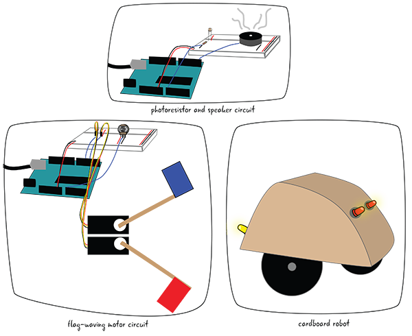
Figure 3-1: Some examples of projects that use the Arduino as part of a circuit
Let’s look more closely at what a circuit is.
What Is a Circuit?
If you’ve ever been to a car race, you know that they refer to the track as a circuit. A circuit just means that there is a completed closed loop, as shown in the circuits in Figure 3-2. The cars pass from the start line and end at the same place.

Figure 3-2: Circuit tracks
The same is true for electronic circuits. An electronic circuit describes a complete and closed loop. A circuit includes all of the electronic components required for a task as well as wires or another material that will let the electricity flow between the connected components, as you can see in Figure 3-3.

Figure 3-3: The flow of the circuit starts and ends with the power source.
Why Are We Making Circuits?
Think for a moment about the light switches in your home as a model. To turn a switch on or off, you must be in physical contact with the switch. In our projects, the Arduino will control the behavior of the electronic components. Our electronic components will be arranged in a circuit, and the Arduino must be part of that circuit in order for it to control the behavior.
Circuits allow the Arduino to connect to the electrical components, turning off and on a variety of objects (speakers, LEDs, motors, etc.) or taking information from the outside world (“How hot is it?”; “Is the switch on?”; etc.). As long as we figure out how to have the Arduino connect to the object, we can control it with electricity and, later, programming.
What Makes Up a Circuit?
There are two main parts that make up a circuit: conductive lines and components.
Conductive Lines
Although most of the focus for a circuit is placed on the components, you cannot have a circuit without some sort of connection between the components. Our computers and electronic devices contain printed circuit boards (PCBs). PCBs, which do not conduct electricity, are composed of base layers of material onto which fine lines of conductive material have been applied, as seen in Figure 3-4. The conductive lines connect components that are soldered to the PCB. If you look at a PCB, you’ll notice the shiny silver lines running between the components, connecting them. These lines are like wires stuck to a flat surface.
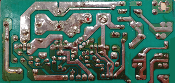
Figure 3-4: Detail of printed circuit board
Components
Components are the other requirement for a complete circuit. We looked at a whole list of components to buy in Chapter 1, “Introduction to Arduino.” The components form the locations that need to be connected within a circuit (Figure 3-5).
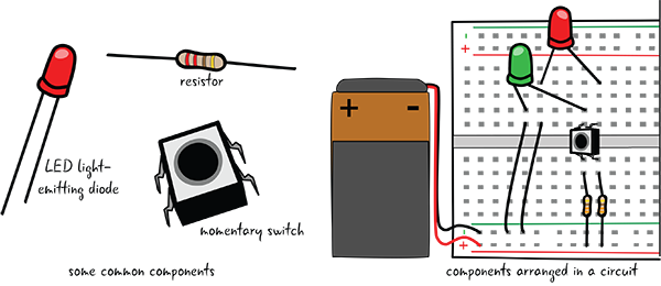
Figure 3-5: Circuits are made of components.
In Figure 3-6, you can see that the leads of the components are acting as conductive lines.

Figure 3-6: Electricity flows through conductive lines.
Where Do We Begin?
The first circuit we’re going to build together is an LED bulb flashlight powered by a battery. This circuit is a great beginner project because the light turning on confirms visually that the circuit is working. The flashlight circuit also demonstrates the basic techniques of circuit building you’ll need throughout all the projects in this book.
Figure 3-7 is a drawing of the circuit when completed, with the parts annotated. We’ll explain what the parts do in detail, partially in this chapter and in forthcoming chapters as well. For now, know that this circuit will be built from an LED, a resistor, a jumper, a 9V battery, and a battery cap arranged on a breadboard, components you met in Chapter 1.
There are many different ways of representing or drawing circuits to convey the necessary information. In Figure 3-7, we have made an approximation of what the circuit will look like when you build it. This isn’t always the clearest way to see what is happening—some circuits have many parts that are connected in complex ways. Schematics are a great way to make a drawing of a circuit that has simplified parts and show how they are connected. Let’s take a closer look at how schematics work.

Figure 3-7: The circuit we’ll build
The Schematic
A schematic is a diagram of the relationships of the electronic components in a circuit. In a schematic, you see the components that are part of the circuit and how they are attached to each other. Let’s start by looking at a simple schematic that represents our basic circuit. We’ll get into the details about what each symbol means in the schematic soon, but for now let’s just take a quick look. Figure 3-8 compares a schematic of the circuit we are about to build to a drawing of the circuit.
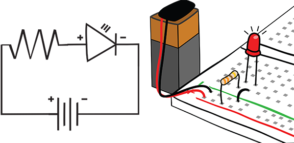
Figure 3-8: Schematic of the circuit with a drawing of the circuit
Why Is It Important to Learn How to Read a Schematic?
Most electronic projects and components are represented by schematics, not necessarily by drawings or photographs. As your electronic skills advance and you want to build your own projects outside of this book, you’ll need to be able to read and draw schematics in order to research your projects, as well as describe and build them.
We’re starting with simple schematics—we’ll build up to more complex representations as we build more complex projects in the book. As you look at schematics online or in other documentation, you may notice that there are sometimes variations in how the symbols are drawn or arranged. Don’t worry if all the schematic symbols don’t look exactly alike, as shown in Figure 3-9.

Figure 3-9: Schematic symbols for LEDs
Diagram of Your Circuit: The Schematic
You’ve learned that a schematic is the standard way to represent the electrical relationships in a circuit. All commonly used electronic components have a symbol to represent them within electronic schematic diagrams in order to make it clear what is attached within the circuit. Figure 3-10 shows a basic circuit of one LED, a resistor, and a battery. The LED has an orientation, a positive lead (anode) and a negative lead (cathode), as mentioned in Chapter 1.
Schematics are primarily concerned with diagramming how the components are connected in the circuit, and will sacrifice clarity in how the components are set up physically to demonstrate better how they are connected electronically.

Figure 3-10: Annotated schematic for the circuit
Table 3-1 shows the symbols for the components that are in our first circuit. The Wikipedia page on electronic symbols is a good place to get an overview of many of the symbols used in schematics: en.wikipedia.org/?title=Electronic_symbol.
Table 3-1: Components with their schematic symbols
| Component | Description | Schematic symbol |

| Battery | 
|
| LED (light-emitting diode) | 
| |
| Resistor | 
|
There are also a few other ways that the symbols from a power source can be drawn, as you can see in Figure 3-11. We’ll cover the concepts of power and ground later on in the chapter, but recognizing these symbols will help you understand what is going on in our circuit.

Figure 3-11: Schematic symbols for power and ground
Drawing a Schematic
You’ve seen an example of a schematic, as well as the symbols that are used in the schematic for our first circuit. How do you connect the symbols to draw a schematic?
We’ll start with the symbol for a resistor in Figure 3-12. Remember that the resistor does not have a positive-negative orientation, so it does not matter which end is which.

Figure 3-12: Schematic symbol for a resistor
We’ll next draw the symbol for the LED and connect it to the resistor with a solid line. Why is the line solid? Remember that we are representing the physical connection between the components in the circuit, just like the conductive silver lines on the PCB.
The positive end, or anode, connects to the resistor as it will in the circuit when we build it, as seen in Figure 3-13. When we attach the battery, the power will flow through the resistor to the positive end of the LED.

Figure 3-13: Resistor connected to anode of LED
Now we add the symbol for the battery and connect it to the symbols for LED and resistor, as shown in Figure 3-14. The negative end of the LED, or cathode, connects to the negative end of the battery.

Figure 3-14: Schematic for the circuit
We can see in this schematic that one end of the resistor is attached to power, or the plus sign on the battery. The other end of the resistor is attached to the positive end of the LED. The negative end of the LED is attached to ground, or the minus sign. Our schematic represents the complete loop of our circuit.
Using a Breadboard
How do we attach the components to build a circuit? If you take a look at Figure 3-15, you can see there is a breadboard beneath all the components.
Why do we use a breadboard? The breadboard allows us to connect all our components. We could never hold all the pieces together with our fingers, and we don’t want to permanently attach them to each other initially. We know that a circuit is a loop and that the components must be connected. The breadboard allows us to connect our components to each other rapidly and gives us the flexibility to easily adjust our circuits. Using a breadboard allows us to rapidly prototype our projects.
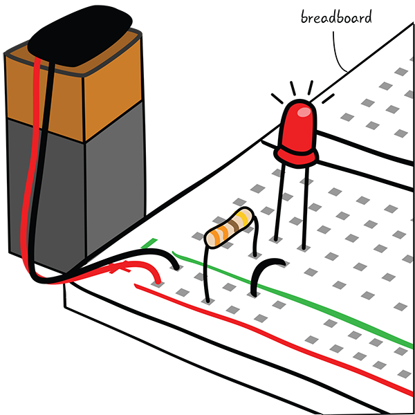
Figure 3-15: The circuit we’ll be building, with the breadboard marked
Breadboard Basics
You’ve seen pictures of a breadboard and circuits assembled on a breadboard. You also know that using a breadboard allows you to quickly prototype circuits and test them out. How is a breadboard constructed? Let’s look at an “x-ray” view of a breadboard.
A breadboard has strips of metal encased in plastic with a grid of holes on the top. The holes, called tie points, are placed at regular intervals and arranged in rows and columns.
In Figure 3-16, you can see the metal strips arranged over rows and columns of tie points. All of the tie points that are connected to one of the metal strips are connected to each other.

Figure 3-16: An “x-ray” view of a breadboard
The rows and the columns are arranged in patterns to make it easy to build circuits with standard electronic components.
The long columns on the far left and right of the board shown in Figure 3-17 are by convention attached to power and ground, and they are called power and ground buses. There is a plus (+) sign or a minus (–) sign at the top of each column. They will be attached to the plus and minus signs on the battery. There is often a red line close to the power bus, and a green, blue, or black line next to the ground bus. Some breadboards, particularly smaller ones, do not have these power buses.

Figure 3-17: Power and ground buses in a breadboard
We’ll explain more about power and ground later. For now, you just need to know that we’ll connect a battery to the buses on one side of the board, and the left and right side buses are not connected. Left or right, it doesn’t matter to which side of the breadboard you attach power and ground, though we’ll connect the battery to the left side of the board. It’s a good idea to be consistent in how you set up your breadboard.
Making Connections
Generally a gap, known as a trench, exists down the middle; it is the same width as some components, to make it easy to plug them into the circuit. The tie points in each row on either side of the trench are connected, allowing you to make connections between components when you place them on the board. Figure 3-18 shows that they do not connect across the trench; each row of tie points on either side of the trench is a discrete row.
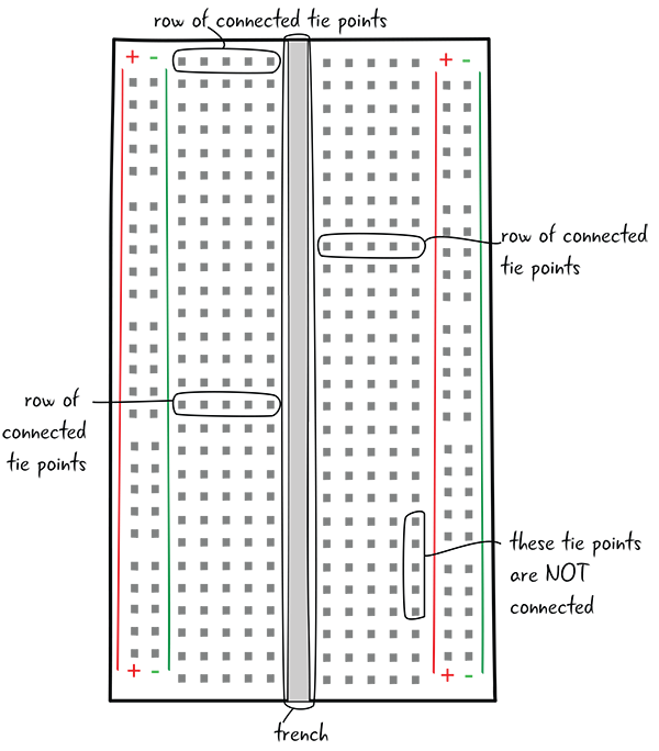
Figure 3-18: Row of tie points in the breadboard
Components can be connected to each other by putting them in the same row of tie points, as shown in Figure 3-19.

Figure 3-19: Connected components in breadboard
Building a Circuit
We’re going to build our first circuit! You’ll need these parts and tools:
- Breadboard
- 9V battery
- Battery cap
- 1 LED
- 330-ohm resistor (bands colored orange, orange, brown, gold)
- Jumper wires
- Needle-nose pliers
Get all of your parts together to start building the circuit in Figure 3-20.
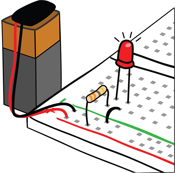
Figure 3-20: The circuit
Step-by-Step Circuit Instructions
We are going to walk you through the steps of making the basic circuit we’ve shown you throughout the chapter. You may not understand exactly how all the parts in the circuit work together yet. Don’t worry about this—we’ll explain more about electricity in a circuit and about each component as we move forward. For now, just follow the steps.
The first parts you’ll need are the breadboard and the 330-ohm resistor. You’ll learn more about resistors later, but right now you just need one resistor that has four bands with the colors orange, orange, brown, and gold.
Pick one corner of the breadboard—we are starting with the upper-left corner. (It doesn’t make a difference if you pick the right- or left-hand buses, but it’s preferable to be consistent.) First put one end of the 330-ohm resistor (with bands colored orange, orange, brown, and gold) into the power bus (marked with the + sign) of your breadboard and the other end into a row of your board. You’ll have to bend the leads a little so you can get them into the board.
Resistors don’t have a forward or backward direction in a circuit, so it doesn’t matter what the orientation is. Each lead or leg is the same. Figure 3-21 shows how the resistor is attached.
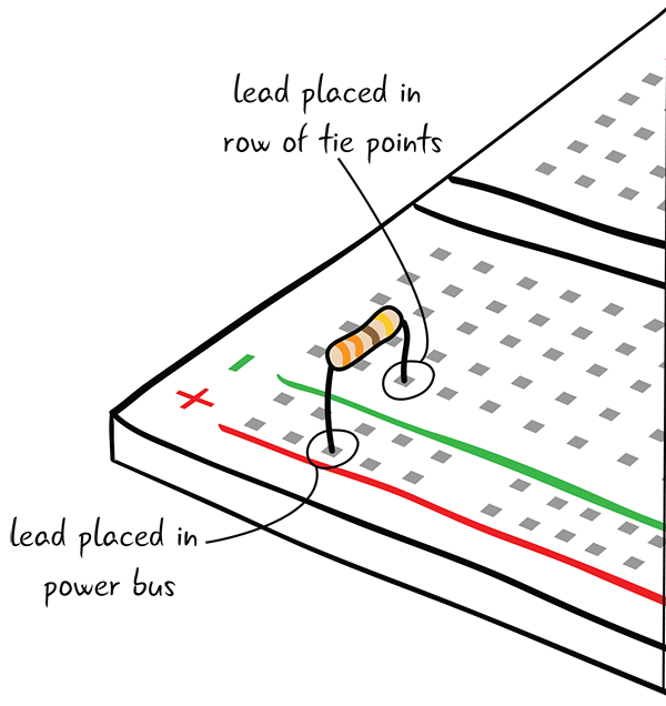
Figure 3-21: First add the resistor.
Next add an LED (Figure 3-22). The anode (long lead) goes in the same row of tie points as the resistor. The cathode (short lead) goes into the next row.
Figure 3-23 shows how one end of the resistor is in the same row of tie points as the anode of the LED.

Figure 3-22: Add the LED.
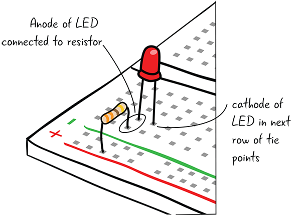
Figure 3-23: LED placed correctly
Next, you should put a jumper connecting the ground bus (marked with the – sign) to the cathode of the LED, as shown in Figure 3-24. Using a black jumper will indicate that it is going to ground. The jumper is just there to make a connection between the cathode and the ground bus.

Figure 3-24: Add a jumper to ground.
Add the battery cap into the breadboard power and ground bus (Figure 3-25). It has metal ends that will fit into the power and the ground bus.
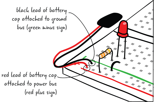
Figure 3-25: Add the battery cap to the breadboard.
A Look at the Battery
Let’s take a closer look at the 9V battery and the battery cap. The top of the battery has two terminals that attach to the snap connectors on a battery cap, as shown in Figure 3-26. The smaller one, next to the plus (+) sign, is the power terminal. The larger terminal, next to the minus (–) sign, is the ground terminal.

Figure 3-26: 9-volt battery up close
Turn over the battery cap, and look at the two snap connectors. The small connector will attach to the ground terminal and the large connector will attach to the power terminal, as seen in Figure 3-27.

Figure 3-27: The battery cap
The snap connectors will only attach properly if the battery is correctly oriented, as shown in Figure 3-28. Your battery cap or holder may look different, but it will follow the same conventions.

Figure 3-28: Attaching cap to battery
Let There Be Light!
Now attach the battery to the cap. Your LED should light up (Figure 3-29). You’ve made your first circuit!

Figure 3-29: Your LED lights up!
This is just the first of many LEDs in the book, but feel good that you have turned on this first one. Next, let’s look at how the battery is providing power to our circuit.
Power for Our Circuit: Electricity
The term power has a specific meaning when talking about electricity, which we’ll explain later. For the moment, power here refers to the fact that electricity comes from our battery, passes through the resistor to the LED, and lights it up. Let’s take a closer look at how this is indicated both on our battery and with the color of the wires in our circuit. We looked at the plus and minus symbols on the battery briefly when attaching the battery cap; now we’ll look at the symbols in more detail.
A Word about Power Symbols
As you can see in Figure 3-30, there is a + (positive) side and a – (negative) side on a battery, the conventional symbols used to mark which side of the battery produces power (positive) and which side is the ground (negative) side. (And you’ve seen the plus and minus signs on the buses on the breadboard.) You also saw that the positive side of the battery attached to the red lead on the battery cap and the negative side attached to the black lead on the battery cap.

Figure 3-30: Positive and negative sides of a battery
Power
The + sign, or the positive, marks the power side of your battery. The convention is that power flows from this side of the battery, and all paths in your circuit must trace back to the power side. Standards also state that all wires that are connected to the positive side are red. This way, anyone who needs to look at or repair your circuit can immediately tell from where the power enters your circuit.
Ground
The – is the negative side of the battery, also known as the ground side. Just as all paths in the circuit must begin with the power side, they must all end at the ground side if you trace them along the entire length. Ground can be thought of as the “zero” side, the place where all power has been used up. All wires that lead back to the ground part of the circuit should be black; that will make it easier to work on your circuits and to know at a glance what parts are connected to ground.
We have looked a bit at power and ground, and you built your circuit. But what if your LED didn’t light up? What steps can you take to find your problem and fix your circuit?
Debugging the Circuit
Something went wrong or doesn’t work right? What if the LED didn’t light up? What might be wrong? Debugging!
Checking your circuit to see what is wrong is called debugging. Debugging is not just about solving the immediate problem, but also about creating a checklist of possible issues and solving them one by one. Sometimes the “obvious” solution is the hardest to find, and by following a checklist, you’re sure not to miss anything.
Are Power and Ground Connected to the Breadboard?
Make sure you connected the leads from the battery cap correctly to the power and ground buses on the breadboard, as shown in Figure 3-31. Remember: Connect the red lead to the bus with the red line next to it with a plus (+) sign at the top and the black lead to the ground bus with a green, blue, or black line (depending on your breadboard) and a minus (–) sign at the top of the breadboard.

Figure 3-31: Leads from the battery cap attached properly to the power and ground buses
Is the LED Oriented Correctly?
Check to make sure you have placed the LED correctly on the breadboard. Remember it has a positive lead (anode) and a negative lead (cathode) and current flows through only if the LED is oriented correctly. The positive lead is longer than the negative lead, as shown in Figure 3-32.

Figure 3-32: Positive (anode) and negative (cathode) leads of LED
Did I Use the Correct Resistor?
Next check to see if you used the correct resistor. We’ll discuss how to select a resistor in later chapters, but if you have used one with too much resistance, the circuit will not have enough power to light up. If you use one that doesn’t have enough resistance, you can destroy your LED. For this circuit, the resistor should have orange, orange, brown, and gold color bands (Figure 3-33).

Figure 3-33: A 330-ohm resistor
These first few debugging steps rely on careful observation and understanding of the circuit basics we have covered so far. Some debugging steps will also rely on tools to enhance your knowledge about what happens in the circuit.
Debugging Circuit Loops: Continuity
Perhaps the most common error in building a circuit using a breadboard is putting the components in the wrong tie points on the breadboard so they are not connected. As you’ve seen, circuits are loops, and if the components are not attached to each other properly, the loop is broken. Continuity is the property that simply means that things are connected, as shown in Figure 3-34.
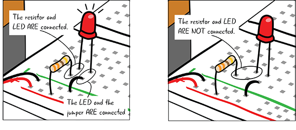
Figure 3-34: Components that are properly connected, and components that are not properly connected
You can check to see whether your components are attached correctly by looking closely at your board. Check carefully that the leads for the LED, resistor, and jumper are in the correct rows of tie points on the breadboard so they are connected properly.
There is another way to test for continuity in a circuit on a breadboard besides inspecting it visually: you can test for continuity with a multimeter (Figure 3-35).

Figure 3-35: A multimeter
The Multimeter
Another way to find out information about your circuits is by using a multimeter. A multimeter is a critical tool for verifying that our electronic and Arduino projects are running correctly and that all of our parts are functional. Your multimeter will be a great tool to use throughout the projects in this book to ensure everything is working as expected. We’ll sometimes call it a multimeter, and sometimes we’ll refer to it as a meter. Now we’ll show you how to use it to test for continuity.
You won’t use a multimeter with the Arduino here, but you will in future chapters. Why are we looking at it now? It will help you debug your first circuit, and it will be invaluable later on when your projects become more complex and you learn more ways to use it. Figure 3-36 shows a few different multimeters.
We are using the meter from SparkFun (SparkFun part number TOL-12966), which we mentioned in the parts list in Chapter 1. The drawings of the multimeter in this book are all based on this model. Your meter may look different, but the principles of setting up the meter and using it will be the same.

Figure 3-36: Multimeters come in different sizes and colors.
Multimeter Overview
Figure 3-37 shows the parts of a multimeter: a display that shows the value of the electrical property you are measuring, and a dial that turns to determine the electrical property you are testing. One end of the probes touches the components you are testing at one end, whereas the other end is attached to the meter in the ports.
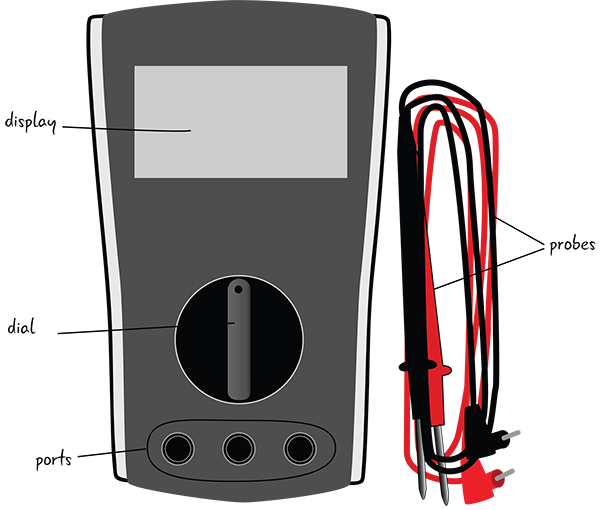
Figure 3-37: Parts of a multimeter
Some meters have off /on buttons, whereas this one turns on with the dial.
Most multimeters are powered by a 9V battery. We don’t include instructions for inserting the battery into your meter. If you get this meter, the instructions will come with it. If you purchased or inherited a different meter, the instructions for replacing the battery will be different.
Parts of the Multimeter: The Dial
Figure 3-38 is a detail of the dial of a typical multimeter marked with some of the electrical quantities it can measure. We’ll explain all these symbols and properties as we progress through the book. Right now just know that there are different properties you can measure: AC voltage, DC voltage, resistance, DC amperage, and continuity.

Figure 3-38: The dial of a multimeter with electrical properties it can measure
We’ll return to these electrical properties and how to measure them with the meter in Chapter 5, “Electricity and Metering.”
Parts of the Multimeter: The Probes
Figure 3-39 shows the probes, the part of the multimeter that touches your circuit, component, or whatever it is you’re testing or measuring. The metal tips of the probes are placed so that they touch the circuit or component. The other end of each probe snaps into the ports on the multimeter. The probes will not be attached to the ports when you unpack the multimeter.

Figure 3-39: Probes of the multimeter
Parts of the Multimeter: The Ports
Now that we’ve looked at the probes of the multimeter, let’s take a closer look at the ports on the meter, shown in Figure 3-40.
It is important that the probes be placed in the correct ports when using a meter. For all measurements, the black probe is placed into the center COM port. The red probe has two different ports in which it can be placed (the outsides as marked). Generally, keeping the red probe in the far-right port is a good practice.

Figure 3-40: The ports on a multimeter
Using the Multimeter
Continuity (Figure 3-41) is an electrical property that shows whether a connection exists between parts. You can use the meter to test this property. It’s a good way to get familiar with the parts of your meter. And you’re going to use it for debugging your circuit!

Figure 3-41: Symbol for continuity
Setting Up Your Meter to Test for Continuity
First, we’ll show you how to use the multimeter to test the electrical connection between the probes on the meter, checking the “continuity” between the probes (Figure 3-42). We’ll then move on to testing continuity in your circuit.

Figure 3-42: Multimeter with the probes touching
This test is a good way to make sure that your multimeter is functioning and to get familiar with how to use it. If the probes are touching, they form a complete electrical loop. The same test can be used later to check if your parts are connected correctly from an electrical perspective.
Meter Settings for Testing Continuity
To test continuity, the black probe goes in the port marked COM and the red probe goes in the port marked mAVΩ, as seen in Figure 3-43.
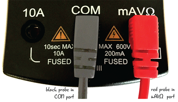
Figure 3-43: Meter port settings to test for continuity
Next, move the dial so the knob is pointing toward the continuity symbol (Figure 3-44).
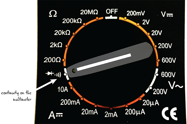
Figure 3-44: Turn the knob to the symbol for continuity.
Testing Continuity
When the probes touch components that are connected, the meter will play a tone if the meter is set to test for continuity. When the probes are attached to the ports correctly, if they touch each other they make an electrical loop. You are making a circuit with your probes in order to test continuity.
Touch the two probes together now to test this out, as shown in Figure 3-45. While the probes are touching, the screen will display “.000,” though it may fluctuate slightly. You’ll also hear a tone that will vary in sound depending on your meter. For continuity, the display numbers are not as important as they will be with the other properties we’ll talk more about in Chapter 5.
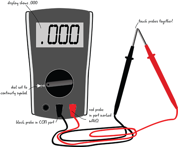
Figure 3-45: The multimeter with the probes touching is a test for continuity.
When the probes touch, as shown in Figure 3-46, you should hear a tone!

Figure 3-46: The probes touch, and a tone plays.
Continuity will help troubleshoot issues in more complicated circuits by identifying when components are not connected to each other or if they are connected in an incorrect spot. We’ll show you more explicitly how continuity can help you solve issues in Chapter 5.
Back to Debugging Our Circuit
Let’s return to our basic circuit. Now that you have unboxed your multimeter and understand what continuity is, let’s apply the multimeter probes to our circuit and take a look at our results.
Testing Continuity in a Circuit
Your meter is already set up correctly to test continuity if you just completed the last exercise. The settings for the dial and probes are shown in Figure 3-47. Check to make certain that the dial is set to the continuity symbol and the probes are in the right ports.
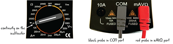
Figure 3-47: Meter settings to test continuity
First, remove your battery from the circuit. Then, turn on your meter and place the probes on one of the leads of the resistor and one of the leads of the LED, as shown in Figure 3-48. It doesn’t matter which color probe touches which lead.
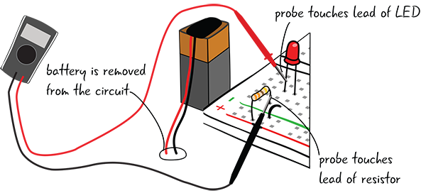
Figure 3-48: Testing the circuit for continuity
If your components are connected, you’ll hear the buzzing sound again, and the settings on the display will read .000 with a possible slight fluctuation.
What if you didn’t get that buzzing sound? Check the connections in your breadboard between each component to see if they are in the proper tie points.
In Figure 3-49, the LED is not connected to any of the other components. The resistor is attached to the power rail and the jumper is attached to ground, but neither is attached to the LED. To fix the circuit, put the leads in the correct tie points.
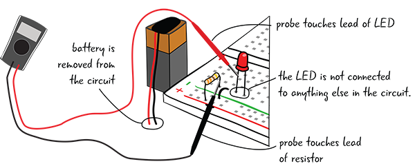
Figure 3-49: The multimeter testing a circuit where the components are not connected
Summary
In this chapter, you learned how to build a circuit and how to debug it. You were introduced to the multimeter, and you learned how to use it to check if all your components were connected. In the next chapter, you’ll set up your Arduino to program it, and then connect it to a breadboard to begin using your Arduino to control components.