
4
Programming the Arduino
In this chapter, you’ll start to see how the Arduino controls electronics with the programs that you write. First you’ll set up the software to program the Arduino on a computer; then you’ll connect your Arduino to a breadboard. We’ll show you how to build an SOS signal light using an LED. You’ll learn basic rules about writing code and get familiar with writing code in the Arduino environment. For this chapter, you need to know how to hook up your Arduino to a computer and how to build a basic circuit on a breadboard.
Arduino, Circuits, and Code: Bringing Everything Together
This is your first opportunity to combine building circuits with basic programming. When you add programming and the Arduino to your circuit, you have more control over the circuit; your LED can flash on and off in different patterns. You’ll learn how to program the Arduino and connect it to a breadboard to build a complex circuit in which the timing of the components in the circuit is controlled by the series of instructions loaded onto the Arduino. To illustrate this, we’ll show you how to create an SOS signal light with an LED that flashes on and off according to timing controlled by the Arduino.
From this point on, most of the projects will include the three parts shown in Figure 4-1: the code, the Arduino, and a circuit on a breadboard. We’ll discuss the combination of all three elements and how they interact with each other in this chapter.

Figure 4-1: Code, Arduino, and the breadboard
We looked at the Arduino and some of its features in Chapter 2, “Your Arduino.” In Chapter 3, “Meet the Circuit,” you learned a bit about small-scale electronics and circuits. We’ll walk you through downloading and using the Arduino IDE in this chapter, which will allow you to upload code, changing the behavior of the Arduino.
Just as we’ll show you the necessary circuits throughout the book, we’ll also include all the code examples you will need to run your projects.
To code, you’ll need software from Arduino installed on your computer. You’ll download and install the Arduino IDE. What’s an IDE? Let’s take a look.
What’s an IDE?
An integrated development environment (IDE) is a software application that allows you to write code and test that code out in the programming language the IDE supports.
If you have experience programming, you may have used another IDE to write, test, debug, and turn your code into something the computer understands. If you haven’t, the Arduino IDE is a good place to start—it is relatively simple and easy to understand.
The Arduino team has designed an IDE for use with their devices that has all the features you need. It has a built-in code editor, which is a program used to write the text files that you create when programming. You can test your code in the IDE and solve any emerging problems with the help of a message area that shows errors in your code and a console that provides more detail about the nature of these errors. It has buttons so you can check your code, save it, create a new code window, upload it to your Arduino, and more. This matches nicely with the basic flowchart for Arduino projects as shown in Figure 4-2.
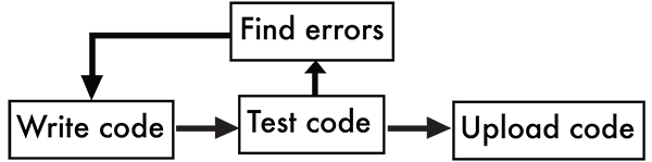
Figure 4-2: Arduino flowchart
The IDE is freely available on the Arduino website at arduino.cc/en/Main/Software. It is possible to program an Arduino using another text editor or IDE, but we’ll stick with using the Arduino IDE in this book.
What’s in the Arduino IDE?
So what’s in the IDE?
- A code editor window where you write your code
- A message area that gives information about your code
- An error console that gives detailed information and helps in debugging
- Menus that allow you to set properties for your Uno and load code examples and other functions
- Buttons to check code, upload it to Arduino, save code, create a new code window, and more
What Is Code?
In basic terms, code is used to give instructions to the computer. We use code to speak in the language the computer understands (in this case, the Arduino language) in order to accomplish a set of tasks or to set up a series of programmed responses. Computers have a hard time understanding what you mean, imply, or suggest. They are not capable of the finer points of language, so we use code to simplify the instructions to a set of commands at a fundamental level.
You’ve seen what’s in an IDE, as well as a basic description of code. Let’s take a quick look at the Arduino IDE.
Arduino IDE: First Glance
Here’s your first look at the Arduino IDE. Don’t worry about memorizing any of the parts or what they do—this is just a first glance. We’ll cover all of the parts in detail later in this chapter and in the rest of the book.
As you can see in Figure 4-3, menus appear at the top of the window. There are also buttons for frequently used functions such as save, an area where you can write code, and some message areas.

Figure 4-3: Arduino IDE
Now that you have an idea about what’s in an IDE (and, specifically, in the Arduino IDE), you can download it and install it on your computer.
Downloading the Arduino IDE: Getting Started
The IDE you’ll use to program your Arduino is free and available on the Arduino site. The installation procedure is slightly different for the Mac platform than for the Windows platform, so we’ll walk you through the download and installation process for both of them.
If You’re Using a Mac
The download page will look something like Figure 4-4. Websites change frequently, as does software, so it may look different when you visit it. Click the link to download the Mac version of the software. Make sure you download the latest recommended version of the Arduino IDE for Mac.

Figure 4-4: Arduino IDE download for Mac
When you click the link, a zipped version of the Arduino IDE will start to download. It will be in the default download location on your computer, most likely the Downloads folder. When it has finished downloading, double-click the zipped file to unzip it. The unzipped file will be named Arduino.app and will look similar to Figure 4-5.

Figure 4-5: Icons for Arduino app
Move the Arduino.app file into the Applications folder on your computer, as shown in Figure 4-6.
You have now downloaded and installed the Arduino IDE on your Mac.

Figure 4-6: Drag the icon to your Applications folder.
If You’re Using a Windows PC
Downloading and setting up the software for a Windows PC is very similar to the steps taken for a Mac computer, but there are a few additional minor steps you need to take in order to ensure the computer and the Arduino can communicate.
First you’ll have to download the software. The URL is the same as that for the Mac download. Make sure you download the latest recommended version of the Arduino IDE for Windows, as shown in Figure 4-7.
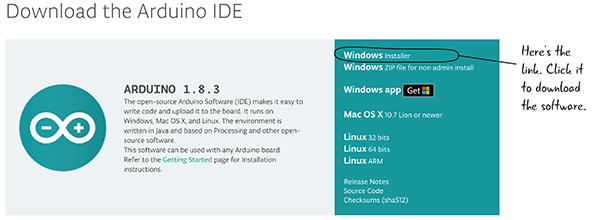
Figure 4-7: Arduino IDE download for Windows
We recommend you use the Windows Installer link. If you are sharing the computer—for example, you’re using a computer at school or work where you are not the only user—you may need to download the version marked “non-admin install.”
When it is finished downloading, there will be an EXE file named with the Arduino version in your default download location, generally the Downloads folder. Double-click on this file to start the installation process.
The first dialog box asks you to agree to the Arduino License Agreement (Figure 4-8). Clicking “I Agree” will take you to the next step of the installation.

Figure 4-8: Arduino license agreement
With the Arduino Setup Installation Options, make sure that the Install USB Driver and the Associate .ino Files boxes are checked (Figure 4-9). Create Start Menu Shortcut and Create Desktop Shortcut are optional but will help you navigate to the Arduino IDE in the future.
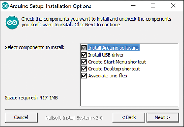
Figure 4-9: Installation options
Depending on your settings and your version of Windows, you may get a Windows security pop-up box asking about the USB Driver installation. Click Install whenever a security dialog box pops up to allow the Arduino IDE to be installed completely (Figure 4-10).
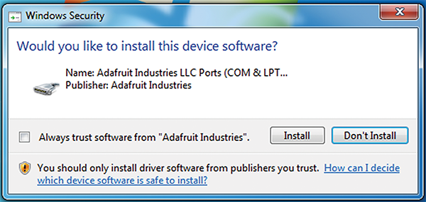
Figure 4-10: Security dialog box
That’s it! Now your Arduino IDE is ready to run on your Windows PC.
Connect Your Arduino to Your Computer
You’ve installed the Arduino IDE, so now it’s time to connect your Arduino to your computer so you can program it.
Plug your USB cord into the Arduino, and plug the other end of the USB into your computer, as in Figure 4-11.
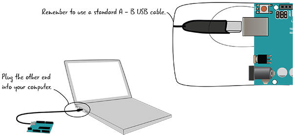
Figure 4-11: Attach your Arduino to your computer.
The LED marked ON should light up, and if your Arduino is brand-new out of the box, the light near Pin 13 should be blinking, just like when you tested plugging your Arduino in for Chapter 2 (Figure 4-12).

Figure 4-12: Indicator LEDs
The Arduino IDE: What’s in the Interface?
Let’s take a look at the Arduino IDE in Figure 4-13 now that you’ve launched it.
The Arduino IDE allows you to check whether your Arduino is connected to the computer, check your code for errors, upload any code you write to control your Arduino, and has a few other helpful options for understanding how the Arduino is behaving. We’ll look at all of the features in much more detail before you start to write code for your Arduino.
A program we write in the code editor for the Arduino is called a sketch. When you launch the software for the first time, you’ll see the bare bones of a sketch. We’ll explain how the code that’s there is used as you start to program your Arduino.

Figure 4-13: Basics of Arduino IDE
You’ll have to configure some settings before you start programming. Let’s look at them now.
Configuring the IDE
Two important settings need to be configured in the Arduino IDE so your computer can communicate with your Arduino Uno. You need to specify which version of the Arduino hardware, or board, you are using, and which connection or port you’ll use for communication between the Arduino and your computer. These settings will be the same as long as you’re using the same Arduino Uno. (The settings will be different if you’re using another Arduino. We’re using the same Arduino for all of the projects in this book.)
Specify the Arduino Hardware Version
You saw in Chapter 1 that there are many different versions of the Arduino. To program yours, you must indicate in the software which version of the Arduino board you’re using.
To do this, go to the Tools menu and select Board, as shown in Figure 4-14. From the flyout menu, select Arduino Uno/Genuino. Once this is set, you’ll have to set a port through which your Arduino will communicate with your computer.

Figure 4-14: Selecting the Arduino board
Specify Which Port You’re Using
There is a port on the Arduino that communicates with a port on your computer when the two are connected by a USB cable. Think of the port as the channel through which the two devices speak to each other. Right now, you need to set up the Arduino IDE so the correct port on your computer communicates with your Arduino.
Selecting the right port looks slightly different on a Mac and a Windows computer. We’re going to look at screenshots for both of them. Remember, you’re setting up your computer to talk with your Arduino Uno, since that is the version of Arduino that we’re using for the projects in this book. Let’s look at Mac first; if you have a Windows PC you can skip ahead to the next section.
Mac Port Selection
To set the correct port for your computer to communicate with the Arduino, go to the Tools menu and select Port, as shown in Figure 4-15.

Figure 4-15: Selecting the correct port
On a Mac, select the port whose description includes dev and cu and that is labeled Arduino/Genuino Uno. Dev is a prefix added by the Mac, cu is short for call-up, and Arduino Uno is the version of Arduino hardware you’re using. In our earlier example, the number at the end of that menu item is 1451; on your screen, this will be different from this example, and it might be different each time you connect your Arduino. In some versions of the software or operating system, you may see tty rather than cu in the lists of ports. That should work as well; what is important is that you see Arduino/Genuino Uno in the port description.
Nothing bad will happen if you select the wrong port, but the Arduino and your computer won’t know how to talk to each other. If it seems that the Arduino and your computer aren’t communicating, take another look at your list of ports and make sure you’ve selected the right one.
Windows Port Selection
Let’s look at the port selection on a Windows machine (Figure 4-16). On a PC, the port names will all start with COM. You want to go to the Tools menu, select Port, and then select whichever COM number matches up with the Arduino Uno/Genuino label under Serial Ports. It will be something like COM3 (Arduino Uno/Genuino).
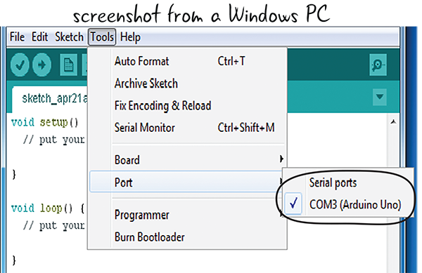
Figure 4-16: Selecting the correct port
Now that you’ve set the port and the correct Arduino board, let’s take a closer look at the Arduino IDE used to create your code.
Understanding the Code Window
We’ve heard about the parts of the Arduino IDE; now let’s take a look at them more closely in Figure 4-17.
As in most software, there are menus that allow you to perform various actions, such as creating new files, saving them, and many more, at the top of the software interface. There are button icons that also allow you to quickly access some of the most often performed actions. Clicking the Verify button checks to make sure there are no errors in your code. Clicking Upload transfers your code from your computer to your Arduino so it can run on your Arduino board. There is a window where you type your program, and message areas that give you information about that program. We’ll explain more about messages as we work in the IDE; for now, know that they tell you if your code has errors, and also information like the amount of space it uses in the Arduino’s memory.
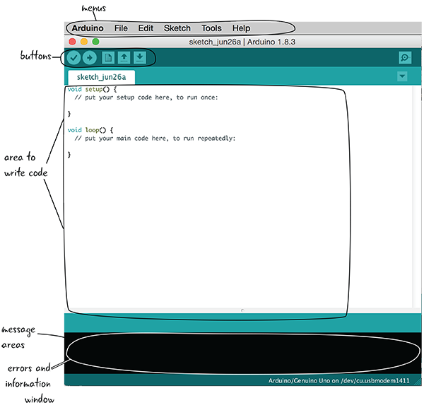
Figure 4-17: Arduino IDE annotated
Let’s look a little closer at the buttons at the top of code editor in Figure 4-18.
These buttons allow you to quickly access the actions that you will perform most often with the code window. These actions include checking if your code has any errors (verifying), sending your code to the Arduino board (uploading), creating a new file, opening a file, and saving it.

Figure 4-18: Buttons in the Arduino IDE
We’ll use all of these buttons in just a moment, but first let’s be clear about what writing a sketch actually means.
The Sketch: The Basic Unit of Arduino Programming
You can think of an Arduino program, or sketch, as one full group of instructions to perform specific tasks. A sketch includes all of the code, or instructions, for that task or tasks. It’s possible to have multiple, separate sketches open at once—just as a spreadsheet program can have more than one sheet open at a time. Let’s take a closer look at what forms a sketch.
Every program you upload to your Arduino is considered a sketch. A sketch can be quite simple or extremely complex. It could turn a single LED on and off, or it could control 10 or more motors based on sensor input. Although each sketch corresponds with one task, that task could be made up of multiple parts. For example, your program may take measurements of the world (like light levels) and use them to trigger speakers and LEDs. All of that would go in one sketch.
The name of the sketch appears in a tab in the upper-left corner of the code editor. Figure 4-19 shows examples of Arduino sketches.

Figure 4-19: A blank sketch window and one with code written in it
Opening an Example Sketch
Before you start to write your own code, let’s explore an example that is included in the Arduino IDE. The IDE has a lot of examples (sample code) that demonstrate many of the things that the Arduino can do built into it. You can load an example into the code window and upload it to your Arduino when it is attached to your computer.
First, open up the example sketch named Blink by selecting File > Examples > 01.Basics > Blink, as shown in Figure 4-20.

Figure 4-20: Opening the Blink sketch
Saving Your Sketch
By default, your Arduino sketches will be saved inside the Arduino folder within your computer’s Documents folder. It is a good idea to continue to save in this space since it makes it easier to return to the files. Arduino also keeps track of past files saved inside this folder in the Sketchbook dropdown in the File menu.
Even though you’re using code from an example, it is best to save it now with a different name so that you can always return to the original unadjusted example code later. That way, when you make changes and save your sketch you’ll know you haven’t saved over the Blink example sketch accidentally. Save your sketch as LEA4_Blink so that you’ll be able to find your changes later.
Save Early, Save Often!
Get in the habit of saving your files. Just like you wouldn’t want to lose work from a paper or another project, saving early and often can help save frustration if for some reason your computer closes the Arduino IDE (losing power, momentary hiccup, etc.). Although the odds of this happening are low, the one time it does you’ll be glad you don’t have to repeat all the work you did because you saved your project and don’t have to worry about it.
Uploading a Sketch to the Arduino
Now that you’ve saved the example sketch with a new name, it’s time to upload it to the Arduino. Before you upload it, let’s check it for errors. Even though you’re using the code that’s built into the IDE, get in the habit of always verifying your code before you upload it.
There are two buttons we talked about earlier that you need to keep in mind when you’re ready to upload your code: Verify and Upload. We’ve highlighted both of these buttons in Figure 4-21.
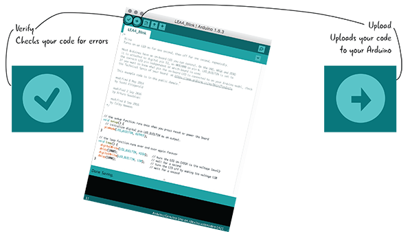
Figure 4-21: Verify and Upload buttons in the Arduino IDE
Step 1: Verify Your Sketch
Verifying ensures that your code is set up correctly. Click the Verify button to make sure there are no errors (Figure 4-22). Unless you made changes to the LEA4_Blink sketch before you saved it, everything will work fine.

Figure 4-22: The Verify button
The message window at the bottom of the IDE shown in Figure 4-23 will display “Done compiling” and show no errors.
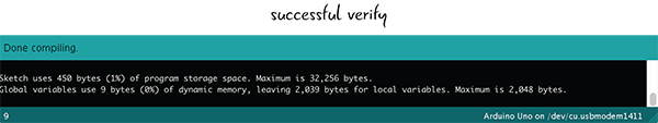
Figure 4-23: The message window
When you verify your code, you will get a message that notifies you that something is wrong if there are any errors in your sketch. The Arduino IDE only knows about programming errors, not mistakes you might have made in setting up your circuit with the Arduino. (We’ll cover those types of errors as we progress through the book.) When we type text into the Arduino IDE window, the code looks like something that humans can read, but the Arduino doesn’t understand how to interpret it. Your computer temporarily converts the code into a language that the Arduino understands when you click Verify to check for these errors.
Step 2: Upload Your Sketch

Figure 4-24: The Upload button
When you click Upload (Figure 4-24), your computer converts the code into a language that the Arduino understands and then immediately begins sending this program over the USB cord to your Arduino.
Uploading Continued: Status Bar and Message Window
Once you click the Upload button, the Arduino IDE window will give you a status bar indicating how much progress the upload has made and a message window with information such as the size of the sketch. That progress bar and message window looks something like Figure 4-25.
Once the file has been sent to your Arduino, the message window will say “Done uploading.”
That’s it! Now your code from the IDE window is running on the Arduino.
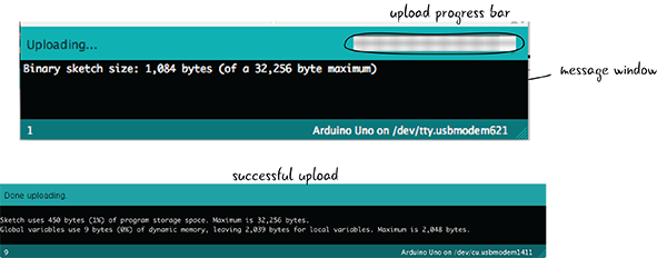
Figure 4-25: Upload progress bar
Run the LEA4_Blink Sketch
Now that you’ve uploaded your sketch to the Arduino, as long as the Arduino has power from the computer through the USB cable, it will keep running. The code that you’ve uploaded to the Arduino contains the instructions that tell the Arduino to blink the light over and over. The LED near Pin 13 will turn on and stay on for one second, then turn off for one second, over and over again. This is illustrated in Figure 4-26. We’ll look at the code in detail shortly and see exactly how it works.

Figure 4-26: The LED blinks.
If your LEA4_Blink sketch is not running, you can turn again to the methodical process used to discover what issue is preventing your code from working. You’ve seen this before with our electronics, and it is known as debugging.
Debugging: What to Do if the LED Isn’t Blinking
If the upload was successful and your LED is blinking, there isn’t anything to fix. But what if the LED didn’t light up? Just as you used debugging to search out issues in your circuit, you’ll debug your code throughout the book, methodically looking for problems that prevent your code from functioning properly. You’ll also look for problems with how the Arduino hardware is set up. If you had any issues with your LEA4_Blink sketch make sure that:
- Your USB cord is tightly plugged into both your computer and your Arduino (Figure 4-27).
- You have selected the right board type and serial port from the menus (Figure 4-28).

Figure 4-27: Make sure your computer is firmly attached to your Arduino via the USB A-B cable.

Figure 4-28: Make sure you have selected the correct board.
If your Arduino seems not to be responding, you can always push the Reset button before uploading, as shown in Figure 4-29. The Reset button will turn off your Arduino for a moment before turning it back on.
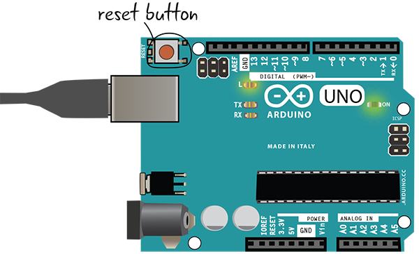
Figure 4-29: The Reset button on the Arduino
You can also try switching your USB port or restarting your computer if none of the above solutions work for you. We’ll cover all sorts of code debugging tricks throughout the book, but these few basic tips concerning the Arduino can save you a lot of headaches later.
The LEA4_Blink sketch will run as long as the Arduino has power, but how does it actually work?
LEA4_Blink Sketch: An Overview
Figure 4-30 shows a screenshot of the LEA4_Blink sketch. This is a quick overview of the parts of the sketch; after we look at it we’ll go over every part of it in detail.
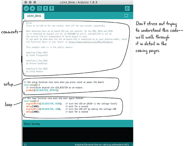
Figure 4-30: LEA4_Blink sketch first look
Comments are notes to the programmer in the text that are not part of your program. In an Arduino sketch, setup() is where you put the parts of your program that happen only once, and loop() is where you put what you want to happen over and over again.
In this sketch, all of the code in setup() and loop() is written in the Arduino programming language. If you look at the code in the Arduino IDE, you will see that parts of the code are different colors; some are orange, some blue, some black. These colors represent some of the different roles of the code. It’s not important to memorize or know these colors; they are just there to help you visually separate the purpose of the various parts.
We’ll look at all the parts of a sketch in detail shortly, but first let’s look at the comments section at the top of the code.
Comments: Letting Others Know What You’re Thinking
Comments in code are used to write notes to anyone who might read your code. This might be you when you return to a sketch you created earlier, or others with whom you are sharing your code. Comments have no effect whatsoever on how the computer interprets the text and are only there to remind you or clue someone else in on what you intended to do, or how the program functions as a whole. We’ll use comments throughout our code examples to help explain sections. It is a good habit to get into writing comments to yourself so that you can return to a sketch later and remember what is going on.
The first part of the LEA4_Blink sketch includes a comment about how the file works. This comment is long, with lots of information, but comments are sometimes short, just a word or two. As you can see from this example, comments sometimes have information about the author of the code and the date. In this case they also tell us that the code is in the public domain.
In the Arduino language, as in many other popular languages, there are a couple of ways to indicate comments. Multi-statement comments start with /* and end with */, which allows for entire blocks of code to be commented out. Single-statement comments start with // and end when you hit Enter to create a new statement. Sometimes the single statement comments are at the end of a statement of Arduino code. Anything written after the double slash (//) will be ignored until the next statement.
As you can see in Figure 4-31, the top section of the LEA4_Blink sketch shows the comments at the beginning of the sketch.
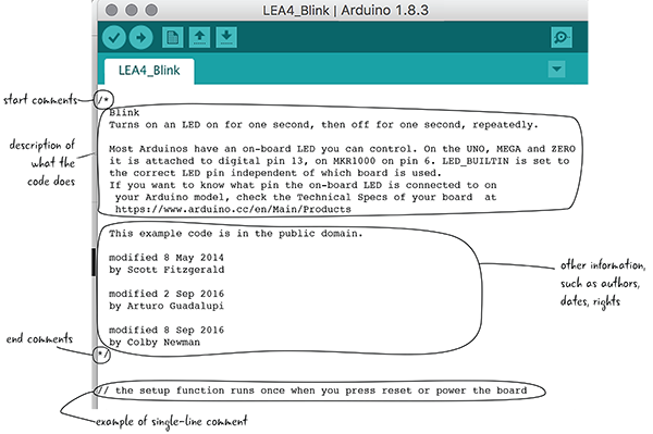
Figure 4-31: Comments at the beginning of the LEA4_Blink sketch
setup() and loop(): The Guts of Your Code
Comments, though important, are not instructions to the Arduino. In an Arduino sketch, there are two basic sections: the setup() function and the loop() function. The diagram in Figure 4-32 shows how setup() and loop() work: setup() happens once, followed by loop(), which repeats over and over.

Figure 4-32: setup() and loop() diagram
setup() is the name of a function that is included in every Arduino sketch. What’s a function? Just think of it as a way of organizing code or instructions to the computer.
Generally speaking, anything that you want to happen only once in your sketch belongs in the setup() function. setup() is run exactly once every time your Arduino is reset.
setup() and loop() Connected
We are going to take a look at the rest of the Arduino code for the LEA4_Blink sketch, but first let’s look at a couple of example projects. We’ll use these example projects to help you gain an understanding of the difference between the setup() and loop() sections of the code.
You’ve seen examples of how setup() and loop() work; now let’s see what the setup() function looks like from the LEA4_Blink sketch you just uploaded and have running on your Arduino.
setup(): Setting Initial Conditions
We’ve discussed comments, and you’ve seen that setup() runs once at the beginning, whenever you turn on or reset the Arduino. Let’s now take an in-depth look at the setup() function in the LEA4_Blink example sketch.

setup() has some parentheses attached to it; we’ll explain why they are needed and what they do later. After the parentheses is an opening curly brace, {, which is very important. Curly braces denote a block of code and mark off the instructions that will happen when the code is run. In this case, whenever setup() is run, all of the instructions will execute one by one. When you are done with the code block, be sure to include a closing brace, }, to tell the Arduino that you are done talking about that section of code instructions.
Let’s take a look at what code instructions happen when setup() is run. For the LEA4_Blink sketch code, there is only one setup() code instruction and one single-line comment.

The first line looks familiar. It starts with two forward slashes, which means that it is a comment. In this case, the comment is telling us the purpose of the second line is to “initialize digital pin LED_BUILTIN as an output.” We don’t yet understand what this means, but we do now know that pinMode(LED_BUILTIN, OUTPUT); sets the built-in LED to be an output. Let’s take a look at the code instruction line without the comment.


Semicolons in the code serve the same purpose as periods in English; they denote that you have reached the end of the line. This keeps the Arduino from misinterpreting your instructions, because it knows you meant to end the line as soon as it sees a semicolon. If you omit the semicolon, you will generate an error in the Arduino IDE and your code won’t upload to your Arduino.

Next, let’s look at the end of the line. pinMode() is followed by a set of parentheses, which contain the text LED_BUILTIN, a comma, and the word OUTPUT all in capital letters. pinMode() is a function that sets our pins to behave in a particular way.

When you call pinMode(), you instruct the Arduino to set the pin with the number you type to act as either an input or an output. Instead of seeing a pin number there, you see LED_BUILTIN—which is there instead of the pin number, because your Arduino Uno knows that LED_BUILTIN means Pin 13. So, 13 is the number of the pin you’ll set to OUTPUT. You haven’t wired anything to the Arduino yet, but the Arduino already has a tiny LED wired permanently as part of the board attached to Pin 13, which is where the word LED_BUILTIN originates. You are setting the mode for Pin 13, telling the Arduino that you plan to use Pin 13 as an output.

OUTPUT means that you want to control whether the pin is off or on. OUTPUT allows you to set the pin dynamically and change its state as your sketch continues.
setup(): It Happens Once
To recap, in our LEA4_Blink sketch setup() tells the Arduino to treat Digital Pin 13 like an output. The Arduino is good at remembering instructions that you tell it about pins, so you need to tell it only once. As long as this sketch is still running, Arduino knows that Pin 13 is an output. If the Arduino gets unplugged or turned off somehow, the first thing that happens when the Arduino restarts (within the setup() function) is that Pin 13 is set as an output. In other words, you don’t need to remind the Arduino what the individual pins do over and over. You’ll put all of your pinMode() functions inside setup() so that they run only once. Figure 4-33 shows the LED blinking.
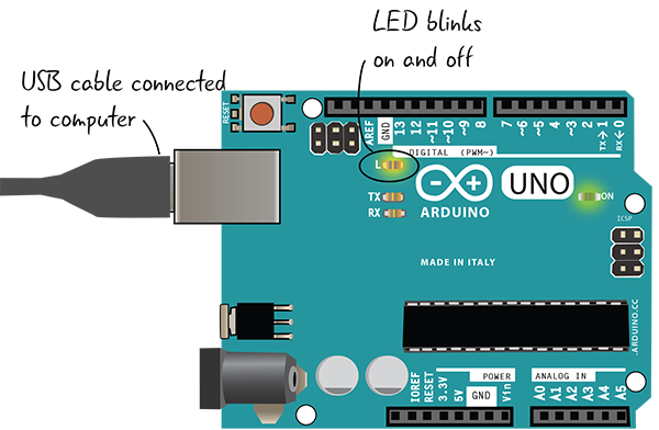
Figure 4-33: The LED blinking
Looking at loop(): What Happens Over and Over
Now that we have seen the setup() function from the LEA4_Blink sketch, let’s take a look at the loop() function.

The loop() function contains the code that you want to have repeated over and over again. As long as the Arduino is running, this code will keep repeating, after the code in setup() has run once.
When you saw LEA4_Blink run on the Arduino, the LED light blinked off and on every second. The code in the loop creates this behavior. Let’s take a close look at what’s in loop() in our sketch line by line.

The first statement of code instructions inside the loop() looks similar to the pinMode(LED_BUILTIN, OUTPUT); statement you saw in setup(). Again you’ll be dealing with LED_BUILTIN, which is a label for Pin 13, since you declared in setup() that your sketch uses this pin. The digitalWrite() function in this context is used to set whether the pin is on or off. When you write, or set the value of the pin to HIGH, you are turning the pin completely on.
When the Arduino gets to this line in the loop(), it will turn on the LED attached to Pin 13. Let’s next take a look at the second line.
Looking at loop(): digitalWrite() and delay()
After you turn the pin on, you want to put a short delay() in the program. This delay() will pause your program, preventing the Arduino from reading the statement that follows for a short time. How long does delay() pause the program? That is up to you. delay() requires that you include between the parentheses the number of milliseconds (one thousand milliseconds equal one second) to wait. In this case, you have stated that the Arduino will wait one thousand milliseconds, or one second, before moving on to the next statement of the program.

Now let’s look at the third line of the loop() function.

This third line of code instruction inside the loop() is nearly identical to the first line, digitalWrite(LED_BUILTIN, HIGH);, except that HIGH has been replaced with LOW. You are still focused on Pin 13, which is the only pin that you use in this sketch. As you learned with the first line, digitalWrite() determines whether the pin is on or off. Using the Arduino to write LOW sets the pin all the way down—in other words, off.
Finally, let’s look at the fourth and final line of the loop(). You’ll put another pause in the program, this time for 1000 milliseconds, or one second. This makes it so that the LED stays off for a full second since the Arduino is paused for this time. The Arduino pauses for one second and then will go back to the first line of the loop() code again, repeating the cycle just described.

loop(): Looking at the Complete loop() Function
Here’s all of the loop() code again, including the comments:
Again, as demonstrated in Figure 4-34, loop() is run continuously, and setup() is run once. Your loop() code will blink the light on and off until the Arduino is unplugged.

Figure 4-34: setup() and loop()
Although the sketches you’ll write throughout the book will become more complicated and include more lines of code, the basics laid out in the LEA4_Blink sketch will continue to be your foundation for good code. Pins only need to be declared as inputs or outputs in setup(), and any code you want to happen more than once should be included in loop(). Remembering these two principles will help immensely as you get into more complex projects.
You’ve seen the basics of an Arduino sketch, and looked at how setup() and loop() functions work. After answering a few questions, we’ll move on to reviewing schematics and look at the schematic for the Arduino. Then, we’ll explain how to hook up your Arduino to a breadboard so you can run LEA4_Blink and light up an LED on the breadboard.
A Schematic of the Arduino
Now that you’ve run your code and lit the LED on the Arduino board, you’re going to attach your Arduino to a breadboard, build a circuit, and run your LEA4_Blink sketch again. You want to learn how to control external components with your Arduino, not just light up an LED on the Arduino itself, so you must attach a breadboard to hold the components.
To run LEA4_Blink on the Arduino attached to a breadboard, you won’t need to make changes to your code. When you set LED_BUILTIN to HIGH in LEA4_Blink, it lights up the LED on the Arduino near Pin 13, and it will also set whatever is attached to Pin 13 (an LED) on a breadboard to HIGH (a.k.a. on).
Before you start to build your circuit, let’s take a look at the schematic for it. Doing so helps you visualize the electronic relationships in the circuit.
Your schematics from now on will include a symbol for the Arduino. Figure 4-35 shows a schematic for the Arduino, with all the digital, analog, and power and ground pins labeled with their numbers or function, placed next to a drawing of the Arduino Uno for comparison. Don’t worry about memorizing the pin numbers and functionality now—we’ll explain more about the pins and their uses later.
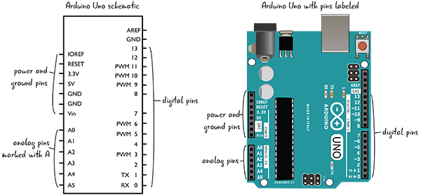
Figure 4-35: Arduino schematic and board
The schematic for the Arduino looks much more complicated than the other schematics you’ve seen previously. Its complexity reflects the number of connections possible with the Arduino hardware. Rather than try to cram this detailed Arduino schematic into the schematic of every circuit you build, you’ll use a simplified version: a rectangle that represents the Arduino, with labels only for the components you’re using in that circuit. Let’s see a full schematic of the circuit you’re going to build with the Arduino.
The Schematic for Your Circuit
For the sake of clarity, when you include the Arduino in your schematics, you’re only going to label the pins that are attached to the circuit you’re building. For example, Figure 4-36 shows the schematic for the circuit you’re about to build. Only Pin 13, 5 volts, and ground are shown, as well as the LED and resistor.

Figure 4-36: Schematic for LEA4_Blink circuit
Now that you’ve looked at the schematic, let’s see how you’re going to build the circuit. You’ll start from the circuit you made in Chapter 3 (Figure 4-37).

Figure 4-37: Circuit from Chapter 3
Building the Basic Circuit
Now that you’ve taken a look at the schematic, let’s build the circuit. You’re going to run your LEA4_Blink sketch and light up an LED on a breadboard. You’re attaching a breadboard with a resistor and LED to the Arduino—the program that runs on the Arduino will not change. The Arduino will be the power source for your circuit when it is attached to a computer with a USB cable.
You will need these parts:
- LED (red)
- 220-ohm resistor (red, red, brown, gold). This is different from the one you used in the previous chapter.
- Jumper wires
- Breadboard
- Arduino Uno
- USB A-B cable
- Computer with Arduino IDE
Figure 4-38 compares a drawing of this project to a schematic of the completed circuit. As you can see, the circuit uses a resistor and LED like the circuit you built in Chapter 3.

Figure 4-38: Labeled Arduino breadboard and schematic annotated
Connecting the Arduino to a Breadboard: First Steps
You want to build circuits with your Arduino, not just light up an LED on the Arduino board, so you’re attaching it to a breadboard. How do you do that?
We first mentioned using the power and ground pins on the Arduino in Chapter 2. These two pins allow you to use electricity from the Arduino to power the components in your circuit, replacing the 9-volt battery you previously used.
To use the pins, start by attaching a jumper from the pin marked 5V to one of the power buses on your breadboard. Then attach a jumper from one of the pins marked GND (which stands for ground) to one of the ground buses on the breadboard. This is shown in Figure 4-39.
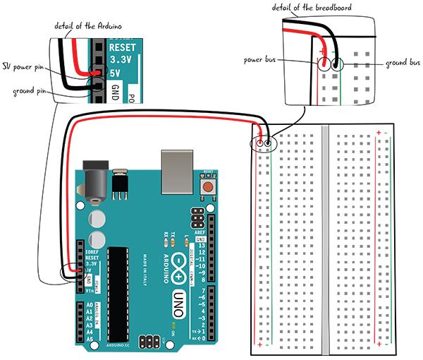
Figure 4-39: Attaching power and ground to the breadboard
It is standard procedure to attach both power (5V) and ground (GND) to the breadboard when attaching a breadboard to an Arduino. Even if you don’t use the power right away, it can be handy to have later as you add more components to the circuit. In this circuit, instead of using the 5V from the power pin, you’ll be using Pin 13 to provide power for the LED.
Building the Circuit Step by Step: Connecting the Pin and Resistor
Now that the Arduino and breadboard are connected, connect Pin 13 on the Arduino board to a line of tie points in the breadboard with a jumper, as you see in Figure 4-40.

Figure 4-40: Adding a jumper from the pin to the breadboard
Next, put one end of a 220-ohm resistor (which has bands marked red, red, brown, gold) in the same row of tie points as the jumper from Pin 13. Put the other end into another row of tie points (Figure 4-41).

Figure 4-41: Adding the resistor to the circuit
Building the Circuit Step by Step: Connecting the LED
Put the anode (long lead, positive end) of the LED in the same row of tie points as the other end of the resistor. Put the cathode (short lead, negative end) in another row (Figure 4-42).

Figure 4-42: Adding the LED to the circuit
Next, add a jumper that connects the cathode (short lead, negative end) of the LED to the ground bus (Figure 4-43).
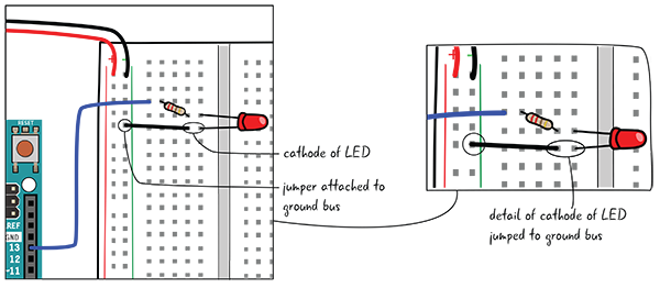
Figure 4-43: Adding a jumper from the LED to ground
Building the Circuit Step by Step: Attach to Your Computer
Finally, connect the USB cable that is attached to the computer to give your circuit power (Figure 4-44).

Figure 4-44: Attaching the Arduino to your computer
The LED should start blinking on the breadboard (Figure 4-45). Your circuit is like the basic circuit you created in the previous chapter, but now your LED flashes on and off, controlled by your Arduino, which is running the LEA4_Blink sketch. You have more control over your LED by using the Arduino; you have added the element of timing.
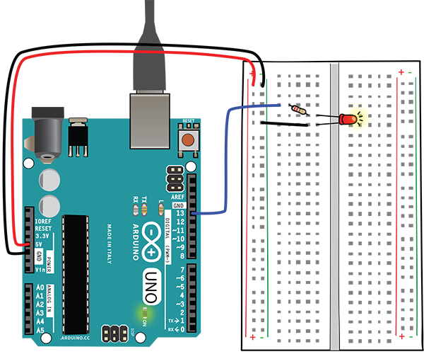
Figure 4-45: The blinking LED
SOS Signal Light: Creating More Complex Timing
While the previous circuit ended up being very similar to the project in Chapter 3, you have accomplished something by hooking it up to the Arduino and discovering the possibilities of code. Earlier in this chapter, you saw that you can make one light blink on and off with a few very simple lines, and the opportunity for complexity just grows from this basic starting point.
Now you’ll work on the code, adjusting it to create an SOS signal light, a light that uses Morse code to convey an SOS message by a blinking light pattern. This is a pattern of three short light flashes, followed by three long flashes, and finally three more short flashes with a long pause at the end before the pattern repeats (Figure 4-46).
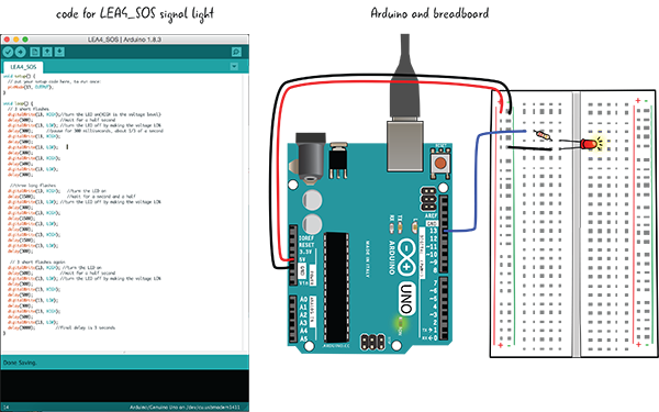
Figure 4-46: LEA4_SOS sketch and circuit
You can see by looking at Figure 4-46 that the hardware (the Arduino and breadboard with components) does not change at all. All the changes to make the LED blink in an SOS pattern will go in the sketch you write in the Arduino IDE. You don’t need to disconnect your Arduino from your computer if you’re adjusting the code—only when you’re adjusting components on the circuit.
Save Sketch and Rename
Select Save As and rename your sketch LEA4_SOS. Some of this new sketch will have the same code you just used, and you’ll be adding substantial new code. The code inside setup() will have one minor change and the code in loop() will become much longer. Let’s review the LEA4_Blink code, then revise the code in loop().
Reviewing and Revising Code: What Do You Change?
Let’s first take a look at the setup() code. After a comment that tells you what the following line does, there is a line that sets LED_BUILTIN, connected to Pin 13 as an output. Instead of leaving it as LED_BUILTIN, you’re going to change this setup() code to include the line pinMode(13, OUTPUT).

Unlike the code in setup(), the code in loop() will be revised and added to extensively. Let’s review the code from the LEA4_Blink sketch before you make changes.
The first line in the loop() sets LED_BUILTIN to HIGH, turning on the LED. delay() then pauses the Arduino—in this instance, for 1000 milliseconds, or one second. Next you set LED_BUILTIN to LOW, turning off the LED. delay() pauses again for 1000 milliseconds. Since the code in loop() repeats over and over again, the LED is blinking on and off.

Let’s look at how you are going to revise loop().
Adjusting loop() in the SOS Sketch
Your code for the SOS signal will be three short flashes of the LED followed by three long flashes, then another three short flashes, with a final pause before the code repeats again. You’ll write the code for the three short flashes first. We’ll look at all of it first, and then break it down line by line. We’ll also reference Pin 13 by its number, replacing all mentions of LED_BUILTIN from the LEA4_Blink code.
Three Short Flashes On and Off
After a comment that states what the code does, Pin 13 is set to HIGH, followed by a delay, then set to LOW, followed by a delay. This is repeated three times.

Let’s take a closer look. The first line of code inside loop() will stay the same as in your LEA4_Blink sketch. As you have seen, this line sets Pin 13 to HIGH.

You’re going to make an adjustment to the next line of code. Remember, the delay() function creates a pause, measured in milliseconds. In your original sketch you paused for 1000 milliseconds, or one second. You want a shorter pause now, 500 milliseconds, or half a second. Let’s change the comments to reflect what your code is doing.

Your next line will set the pin LOW, or turn off the LED. You can leave this line as it is, since there is no need to change it from the LEA4_Blink sketch.

However, you’ll make a change in the number of milliseconds in delay(). In your LEA4_Blink sketch, the delay was 1000 milliseconds, or one second. Now you’ll pause 300 milliseconds, about a third of a second. You’ll adjust the comments as well.

Here is the complete cycle:

You want to repeat turning on and off the LED three times. Let’s first add a comment indicating what this part of the code does, then copy two more cycles of turning on and off. Here is the code again:

Now let’s look at the code for the longer flashes.
Adding the Three Long Flashes On and Off
The three long flashes section is very similar to the short flashes section. After the pin is set to HIGH, the delay() function pauses for 1500 milliseconds, or one and a half seconds, keeping the LED turned on. Let’s look at all of the long-flash code first. A comment states what the code immediately following does.

Again you have a repeating cycle of setting the pin to HIGH, pausing, setting the pin to LOW, pausing, three times. First you set the pin to HIGH.

Then you pause with the delay() function, this time for 1500 milliseconds, or a second and a half. The comments have also been changed to reflect the adjusted amount of time.

Just as in the code for the short flashes, you must set the pin to LOW, then pause with delay().

You’ll then use the same number of milliseconds as delay() between the short flashes, 300 milliseconds.

Again, you’re creating a cycle that is going to repeat. After the last short flash cycles, you’ll make the pause last longer to make each SOS signal discrete. Let’s look at that, and then look at all the code in loop() together.
This final line of code in loop() pauses the Arduino for 3000 milliseconds, or 3 seconds. This follows a line that has set Pin 13 to LOW. You want a longer pause between each SOS signal to make sure viewers can distinguish between cycles.

All of the SOS loop() Code
Now let’s look at all of the code in loop(). It is long, so we’re breaking it up into sections.


After you’ve written your code for the SOS signal light and saved it, click the Verify button to check for errors (Figure 4-47).

Figure 4-47: Successful verify
If it is okay, make sure your computer is attached to your Arduino, and that you have the correct board and port selected. Then click the Upload button to upload your code to the Arduino (Figure 4-48).

Figure 4-48: Successful upload
What does the LED look like now on the board?
SOS Signal Light Flashes On and Off!
Your LED should now be flashing an SOS signal: three short bursts, followed by three long flashes, three short bursts again, a 3-second pause, then the whole pattern starting over and over again. There are other, more efficient ways to write the code, but for now we want you to make adjustments and understand what the code is doing by seeing the results in your circuit (Figure 4-49).

Figure 4-49: LED flashing SOS
Summary
You’ve set up the Arduino IDE, learned how to verify and upload code, seen how to attach a breadboard to an Arduino, and explored writing a sketch in the Arduino programming language. You can download the code for LEA4_SOS from https://github.com/arduinotogo/LEA/blob/master/LEA4_SOS.ino.
In the next chapter, you’ll learn more about writing code in the Arduino programming language and how to attach different types of components to a circuit.