
8
Servo Motors
In this chapter, you’ll add motion to your Arduino projects. You will be using servo motors, as shown in Figure 8-1.

Figure 8-1: Hobby servo motors
Servo motors are a type of motor that can be easily programmed to rotate to a precise position. A servo motor contains a set of gears and a control mechanism that rotates a shaft a specified number of degrees. Because servos are relatively easy to control, they are a good introduction to using motors in your projects. Although there are many types of servos, the ones that we recommend you use can rotate between 0 and 180 degrees.

Figure 8-2: Diagram of degrees of rotation
First, you’ll be turning your servo continuously with an example sketch from the Arduino IDE. Then, you’ll control a servo with a potentiometer. Finally, you’ll add a second servo to the circuit and adapt a sketch so that the movement of both servos is controlled by turning the potentiometer.
We’ll also cover some programming concepts that you haven’t encountered before, including for loops and custom functions.
The type of servo motors you’ll be working with are called positional rotation servos. They are limited to 180 degrees, or one half of a full rotation of movement; degrees of rotation are shown in Figure 8-2 (previous page). They are accurate to any degree within that range, meaning if you need the shaft of your motor to point to an exact spot, they are a great fit.
Servo motors are used in a wide variety of applications, including hobby model airplanes, robotics, and art projects of all shapes and sizes.
Waving the Flags
Figure 8-3 shows a drawing of the first project you’re going to build. We’ll review a bit about analog data, look more closely at servos, and then get started building.
Analog Data Review
You learned in the previous chapter that analog data can refer to any information that has more than the two possible values that digital information can hold (described alternately as 1 or 0, true or false, HIGH or LOW). In your Arduino sketches, you saw that the number of possible values was often mapped to a particular range—for inputs, a value between 0 and 1023, and for outputs, a value between 0 and 255. Having a wider range of values allows you to do more than just turn your components on or off.
Servo motors use precise positioning. You’ll use analog data in order to set the direction the shaft of your motor is facing in the projects you build in this chapter.
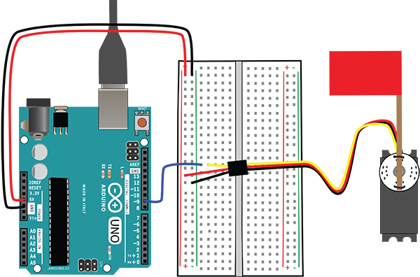
Figure 8-3: The servo will turn and wave the flag.
Servos Up Close
As we have said, many types of servo motors are available. We recommend that you use a motor with a range of 180 degrees that runs on 4.8V to 6V. This type of standard servo is commonly available from many online vendors or from hobby shops or stores that sell electronic components.
Parts of a Servo
The mechanisms that turn the servo (motor, gears, and circuit) are enclosed in a case. The spline is the part of the movable shaft that extends through the case. The horn, or arm, attaches to the spline. A screw holds the horn in place on the spline. The packet of mounting materials that comes with your servo will generally have a variety of horns that you can attach so that you can switch them depending on the nature of your project, as well as some screws and other fasteners. The servos are designed to make it easy to unscrew a horn and replace it with another one. Servos also generally have mounting flanges on the front and back, making the servo easy to attach to your projects.
A cable is connected to the front of the case near the bottom. This has three color-coded wires; the black wire will be attached to ground, the red wire will be attached to power, and the third wire, sometimes yellow, sometimes blue, sometimes white, is the control wire. You will be connecting the control wire to a pin on the Arduino. The servo has a plug, or connector, at the end of the cable to attach it to a circuit. Figure 8-4 shows a servo with and without a horn attached.

Figure 8-4: Servos annotated, one with the horn and one with the horn detached
The different styles of horns that come with your servo allow you to attach the correct horn for the project you are building (Figure 8-5).
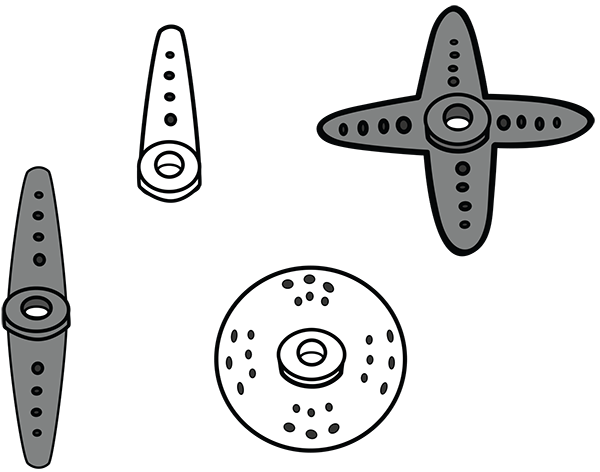
Figure 8-5: Some servo horns
Building the Servo Circuit Step by Step
You’ll need these parts:
- Standard servo motor
- Breadboard
- Jumper wires
- Wooden coffee stirrer or strip of cardboard
- Tape
- Colored paper
- Arduino Uno
- USB A-B cable
- Computer with the Arduino IDE installed
Figure 8-6 shows the schematic and the drawing of the first circuit you are going to build. As usual, the power and ground buses on the breadboard are attached to 5V and GND on the Arduino. You can see that the servo has three wires: one attached to power, one to ground, and one to a pin on the Arduino.

Figure 8-6: Schematic and drawing of our first servo circuit
There are a few things you should know about the servo that will make it easy to set up.
Preparing the Servo
You’ve seen that the servo comes with a packet of different horns. You might want to swap out the horn that is attached to your servo when you purchase it. Use a small screwdriver to remove the screw attaching the horn and replace it with another, as shown in Figure 8-7. We are using the circular horn in our examples.
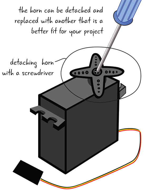
Figure 8-7: Removing the horn
We have made a flag with a coffee stirrer and a piece of colored paper. A strip of cardboard with a piece of colored foam would also work. Make a flag with whatever materials you have lying around and attach it to your horn with wire, as shown in Figure 8-8.

Figure 8-8: Attaching the flag to the servo horn
Before you attach your servo to the breadboard, you will have to add jumper wires to the plug/connector on the servo. As you know, there is a control wire, a wire that goes to power, and one that goes to ground. Follow the color conventions (red wire connected to power, black to ground) as usual. If you have a jumper that’s the same color as your control wire, use that, or use a color that is distinctive from the red and black wires. In our example (Figure 8-9), the control wire is yellow, but sometimes that wire will be another color, such as white.

Figure 8-9: Servo connector up close
Attaching the Servo
Attach jumpers from GND on the Arduino to the ground bus on the breadboard and from 5V on the Arduino to the power bus.
Now attach your servo to the breadboard. Attach the red power jumper to the power bus, and the black ground jumper to the ground bus. Then place the control jumper wire in its own row of tie points (Figure 8-10).
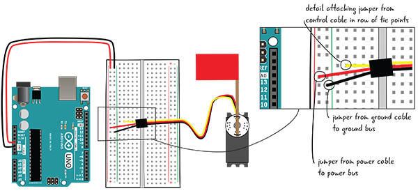
Figure 8-10: Attaching the servo to the breadboard
Next, attach a jumper from Pin 9 to the same row of tie points as the jumper from the control cable, as seen in Figure 8-11. You are attaching the servo to Pin 9 because that is the pin it’s attached to in the sketch you will be downloading. It could be attached to any of the digital pins, 2 through 13.

Figure 8-11: Attach the control wire of the servo through a jumper to Pin 9 on the Arduino.
You’re now ready to download the sketch from the Arduino IDE.
Attach Your Computer and Download the Sweep Sketch
Now that you have completed wiring your circuit, you need to download a sketch to your Arduino in order to run your servo. The Arduino includes a few sketches about using the servo motor, and for this first example, you’ll use the Sweep sketch included in the Servo folder of example sketches (File > Examples > Servo > Sweep).
When you have opened the sketch, save it as LEA8_Sweep. If you haven’t already done it, attach your computer to your Arduino and upload the sketch.
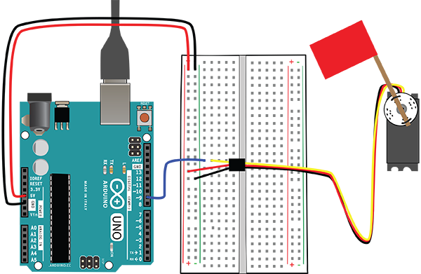
Figure 8-12: The flag waves.
Wave the Flag!
You should begin to see the servo motor swing the flag attached to the horn 180 degrees in one direction, and then reverse directions and swing back to its starting position (Figure 8-12). It will continue to loop these movements one after another for as long as the Arduino has power. Let’s take a closer look at the code and explain what each line is doing.
LEA8_Sweep Overview
In our breakdown of some of the sketches in this chapter, we have removed the comments section for readability. Figure 8-13 shows a quick look at the sketch.

Figure 8-13: LEA8_Sweep overview
Initialization
The first thing you see in the initialization section is a line of code that is going to add functionality to your Arduino. The include statement tells your Arduino to load a library, which will extend the capabilities of your Arduino. Rather than having to write all the code yourself, including libraries gives you access to extra functions that other people have written that expand the possibilities of the Arduino.
How do you add a library? We use an include statement, which starts with a # followed by the word include. An open angle bracket follows, with the name of the library, in this case Servo, and the extension .h next. A closing angle bracket completes the statement, and there is no semicolon in this instance.

The Arduino IDE has many libraries already loaded, and it also allows you to load new libraries if you want to have access to them. For now, we are just concerned with the Servo library and what it does.
If you look at the next line of our initialization section, you see a new type named Servo. After loading the Servo library, you can create a servo object, which has functions that allow it to control servo motors. This line creates a servo object and stores it in a variable named myservo.

We have not discussed objects before, and an in-depth discussion of objects is beyond the scope of this book. Think of an object as a template with a set of attached functions and properties—that is, you can create several different servo objects in your sketch based on the template. Although each one follows the same basic structure, you can modify their properties, such as position.
The last line in our initialization sketch creates a variable named pos, which is set to 0. This variable will be used to set the position of the servo. If you change this value and again send it to the servo, the motor will update with its new position. You will see the code that changes these values within the loop() code.

Inside setup()
Our setup() section includes just one line in this sketch. attach() is a new function made available to your Arduino from the Servo library that allows you to connect the servo object that you named myservo to a pin on your Arduino. That way, whenever you refer to myservo you are referencing the pin to which you have attached myservo, and you will be able to control the servo that is attached to that pin. In this project, the servo motor is attached to Pin 9.

Inside loop()
This loop() code is a little different than what you have seen in the past, and will introduce you to our next programming concept: the for loop. Let’s take a look at the code; then we will break it down.

What’s a for Loop?
There are times when you might want to repeat something a certain number of times or until a particular condition is met. The for loop allows you to repeat something a number of times based on some conditions. In your sketch, you are setting the position of the shaft of the servo motor with a for loop.
Let’s first take a closer look at an example of a for loop before you see exactly what it does in your sketch. In the Arduino language, after the keyword for, the for loop has three parts: the initialization, the condition or test, and the iterator.

Here’s how the parentheses and curly braces are used in a for loop. The parentheses mark off the initialization, condition, and iterator section. The curly braces mark off the block of code, or the statements to be executed if the condition is true.

Now let’s look at an example of a for loop in the syntax of the Arduino language. This for loop prints integers from 0 to 9 in the serial monitor.

How Does a for Loop Work?
In what order do the parts of the for loop get executed? Let’s take a look at Figure 8-14.

Figure 8-14: for loop flowchart
The first thing that happens in our for loop is the initialization (Figure 8-15). You create a temporary variable to count how many times you execute your for loop. The for loop will happen a certain number of times.

Figure 8-15: The initialization is the first step.
How many times will the for loop happen? This depends on the next part of your for loop: the test, shown in Figure 8-16. If the condition in the test is true, then the statements inside the curly braces will get executed. Once the test is no longer true, the for loop will end. We will talk more about the different types of conditions you’ll create for the test in just a moment.

Figure 8-16: The condition is tested.
If the test evaluates to be true (Figure 8-17), the statements/instructions get executed. Then the value is iterated. This often means that you increase the count of your variable by one, but you can also alter the variable in a number of other ways to continue the for loop. Once you have iterated your variable, the for loop returns to the test. If the test continues to be true, the statements inside the curly brackets get executed again, and the value is iterated.

Figure 8-17: If the condition is true, execute statements, then iterate.
It is only when the test is false, shown in Figure 8-18, that the for loop ends.

Figure 8-18: The for loop ends when the test evaluates to false.
Let’s look at the cycle again with the code from our example (Figure 8-19).

Figure 8-19: The for loop flowchart with code
Before we move on, let’s look more closely at the condition, or test, section of the for loop, which requires discussing the idea of an operator.
Operators
An operator is a mathematical or logical evaluation of values that are useful in evaluating the test in the for loop. In basic arithmetic, addition, subtraction, multiplication, and division are all examples of operators. There are a few different types of operators.
Comparison Operators
Let’s take a closer look at the test. You see the variable i, then the symbol < followed by 10. What does this mean? In English, it means is the variable i less than the integer 10? You know that the variable i was set to 0 in the initialization of the for loop. The symbol < stands for “is less than”; it checks to see how the value of i compares to the value of 10. In this context, it is called a comparison operator. Comparison operators are used in logical statements, like the test in a for loop, or in a conditional statement, to determine whether a statement is true or false.

Table 8-1 shows the commonly used comparison operators in the Arduino language.
Table 8-1: Logical comparison operators
| Comparison operator | What it means | Example | What the example means |
> | Greater than | x > 0 | x is greater than 0 |
< | Less than | x < 10 | x is less than 10 |
>= | Greater than or equal to | x >= 0 | x is greater than or equal to 0 |
<= | Less than or equal to | x <= 10 | x is less than or equal to 10 |
== | Is equal to | x == 10 | x is equal to 10 |
!= | Is not equal to | x != 10 | x is not equal to 10 |
Compound Operators
While we’re on the topic of operators, you’ll notice that a different type of operator is used in the iterator section of our for loop. The variable i is followed by +=, followed by 1. In English, this means you are adding 1 to the variable value. The symbols += indicate that you want to add whatever is on the right side to the variable on the left side. In our example, it means add 1 to the variable i.

This type of operator is called a compound operator. Compound operators perform a mathematical operation of some kind. Table 8-2 lists commonly used compound operators in the Arduino language. In each of the examples in Table 8-2, x initially is set to 10.
Table 8-2: Results of using a compound operator when x initially equals 10
| Compound operator | What it means | Example | What the example means |
++ | Add 1 | x++ | x now equals 11 |
-- | Subtract 1 | x-- | x now equals 9 |
+= | Add value on right to value on left | x += 2 | x now equals 12 |
-= | Subtract value on right from value on left | x -= 2 | x now equals 8 |
*= | Multiply value on left by value on right | x *= 5 | x now equals 50 |
/= | Divide value on left by value on right | x /= 2 | x now equals 5 |
The for Loop in the Sketch
So how can you employ for loops to help you move your servo? Let’s take a look at the first for loop in our code. Breaking it down, in the initialization you set the pos variable to 0. The condition checks to see if the pos variable is less 180, and if so, a 1 is added (iterated) to pos. You didn’t have to use int here to indicate the type of pos, because pos was declared in the initialization section.

What instructions are executed each time through the for loop? As long as the value of i is less than 180, the Arduino will write the value of pos to the motor, which will move the servo motor to some position between 0 and 180 degrees. After the Arduino has written this position, there is a delay of 15 milliseconds.
Since the for loop continues for every value between 0 and 180, the servo motor will move from 0 degrees until 180 degrees in the first for loop. This will take a few seconds—there is a very short pause between each movement—but the motion overall will look relatively smooth. If you remove or adjust the length of the delay, the smoothness of the movement will change.
Why is the for loop counting between 0 and 180? Because that represents the range of movement that the shaft in your standard servo motor can move. Think of this as 0 to 180 degrees.
The second for loop in this sketch functions in much the same way. Instead of starting at 0, it starts with the pos variable equal to 180. What’s 180? The second loop needs to start with the last position of the first loop, which is also the end position of the servo.

Besides having a different starting point, this second for loop also decreases by one through each pass of the for loop. That way, the servo motor starts at 180 degrees and slowly rotates back to 0 degrees.
Once the second for loop has finished, the full Arduino loop() function has also finished. The Arduino will then return to the beginning of the loop() and repeat the steps, as you have seen with the other loop() functions.
Add Interactivity: Turn the Flag
You now have a basic understanding of how the servo motor functions with your Arduino code, so let’s try making your servo circuit interactive. Rather than the Arduino moving the servo at a steady pace continually, this next sketch uses information from a potentiometer to position the shaft of the servo motor. As you turn the knob, the shaft of the servo motor will move.
You will use the Knob sketch that is also included in the servo motor examples in the IDE. Before you upload the sketch, though, let’s adjust your circuit by adding the potentiometer.
Adding a Potentiometer Step by Step
Adding a potentiometer to the circuit allows you to control how the flag waves and to set it to a precise position. If you completed the first circuit with the servo, you can leave the servo control wire attached to Pin 9 on the Arduino, the power line attached to the power bus, and the ground wire attached to the ground bus. You will be adding only the potentiometer to the circuit.
You’ll need these parts:
- 1 10 K potentiometer
- Jumper wires
Figure 8-20 shows the finished circuit with the schematic.
Place the potentiometer in the breadboard, as shown in Figure 8-21.
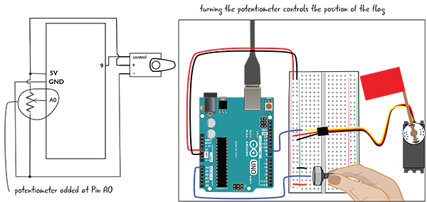
Figure 8-20: Circuit with the potentiometer added
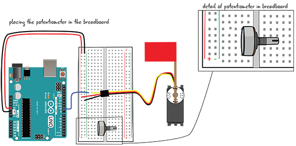
Figure 8-21: Adding the potentiometer to the breadboard
Connect one end of the potentiometer to the ground bus with a jumper. Connect the other end of the potentiometer to the power bus with a jumper. Connect the middle pin of the potentiometer to Pin A0, one of the analog input pins (Figure 8-22).
Now that you’ve wired your circuit, it’s time to open the next sketch in the Arduino IDE. This sketch is located under File > Examples > Servo > Knob. Once you have opened it, save it as LEA8_Knob. Hook up your computer to your Arduino. Click Verify to check the code, and then click Upload to load it to your Arduino.
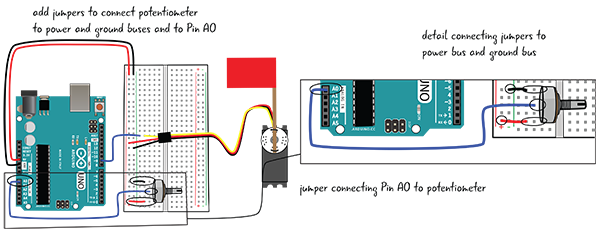
Figure 8-22: Adding jumpers to the potentiometer
Now when you turn the potentiometer, your flag should turn, too.
How Does the Sketch Change When We Are Using a Potentiometer?
Let’s take a quick look at the sketch. It is similar to the LEA8_Sweep sketch—with a couple of important differences that we will look at closely.

LEA8_Knob Explained
Just like with LEA8_Sweep, this sketch controls the position of the horn attached to the shaft of the servo motor, depending on what value the Arduino sends to it. However, this time you have control over how much it turns, since as you turn the potentiometer, you change the value that the Arduino receives and sends to the servo.
Initialization
In this servo sketch, as with the previous one, the first thing you see in the initialization section is the include statement that loads the Servo library. As you’ve seen, libraries extend the abilities of the Arduino to perform specific functions or interact with some types of technology in a streamlined way so that you can write simplified code.

Looking at the next line of the initialization section, you see that, as in LEA8_Sweep, you’re creating a new servo object named myservo. This object will be able to access the functions of the Servo library to communicate with the servo motor.

The initialization section also contains a variable for the analog pin to which your potentiometer is attached. We covered this in Chapter 7; by connecting the potentiometer to Analog Pin 0 you are able to take readings between 0 and 1023 instead of the HIGH or LOW reading you get from a digital pin. Finally, the last line in the initialization sketch creates a variable called val, which you will later use to store the value coming in from the potentiometer and send it out to the servo.

The Code in setup()
The setup() section includes only a single line for this sketch. Again, you use attach() to connect the Arduino to the servo object that you named myservo to a pin on your Arduino. That way, whenever you refer to myservo, you are referencing to a particular pin much in the way that you have seen with digitalWrite() and a pin name. In this case, your servo should be wired so that it is attached to Pin 9.

The Code in loop()
The loop() code section looks similar to what you did in Chapter 7. The first step is to use the analogRead() function to read the value from the potentiometer on Pin A0 and store it in the variable val. This will set val to a value between 0 and 1023, which as you know is the range of possible values from an analog pin.

Next, you use the map() function to adjust the value from your potentiometer reading to match up with the degrees of motion for your servo motor. Since your servo motor is able to move 180 degrees, you will scale the value from 0 to 180. That way, when you send the value to the servo motor, it will already be in a value given in degrees. This new scaled value is then again saved in your val variable.

The next step is to write out your scaled val variable to the servo attached to Pin 9 using the write() function of the servo object. It is worth noting again here that it will not move the servo an additional val number of degrees, but that it will move to the val number of degrees from 0. For example, if val is equal to 90, it will always move the servo shaft to the midpoint.

The last line in the loop() code delays the Arduino program for 15 milliseconds. This very short delay time will let the servo move to the correct position since the movement is not instantaneous. It will also give the Arduino slightly more time between potentiometer readings to ensure a more accurate reading overall.

Two Flags Waving: Add a Second Servo Motor
Let’s add another servo motor to the circuit. You’ll use the information from the potentiometer to set the position of both servos. You’re making a flag-waving signal system.
In the sketch for this project, you’ll learn how to write a custom function, and you’ll also learn more about using logic in conditional statements.
If you built the circuit for the LEA8_Knob sketch, this circuit will be almost the same—the only addition is the second servo motor.
You’ll need the following:
- Servo motor
- Jumpers
- Coffee stirrer or cardboard strip
- Colored paper
- Tape
Figure 8-23 shows the schematic for the circuit, as well as a drawing of the completed project.
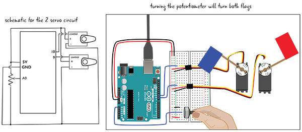
Figure 8-23: Two-servo circuit and schematic
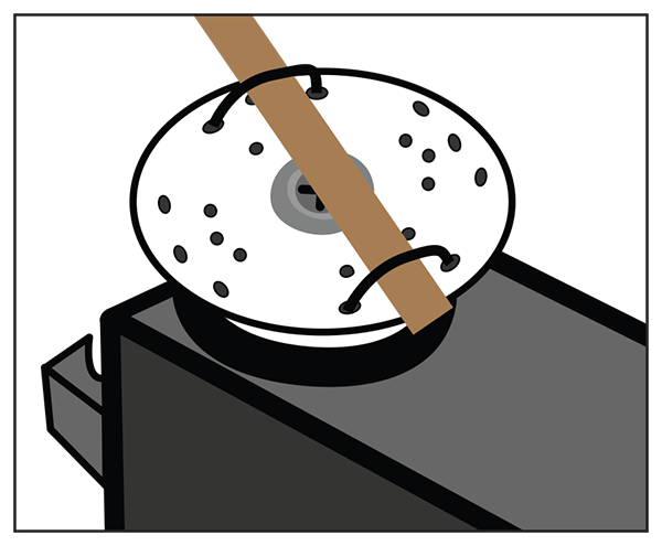
Figure 8-24: Attach the flag to the servo horn.
First attach the wooden stirrer with the paper flag to the servo horn, as you did with the first servo motor (Figure 8-24).
Attach the jumpers to the servo connector (Figure 8-25), matching the colors for power and ground, and attach the control wire.
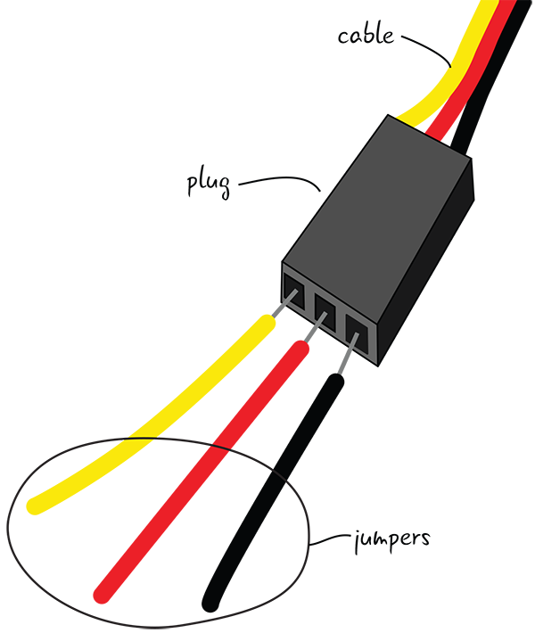
Figure 8-25: Attach jumpers to the servo connector.
Now attach the jumpers to the breadboard, as shown in Figure 8-26. As you did before, connect the jumper connected to the power cable to the power bus and the jumper connected to the ground cable to the ground bus. The control wire connects to a row of tie points. Finally, connect Pin 10 to the same row of tie points as the jumper from the control cable.
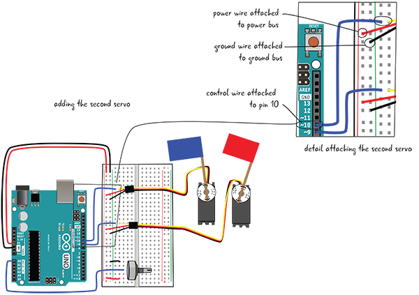
Figure 8-26: Attaching the second servo
Before you attach the Arduino to your computer, you must make some adjustments to the code. Let’s look at the sketch.
LEA8_2_servos, First Look
Save LEA8_Knob as LEA8_2_servos. You will be adjusting this code. In the LEA8_2_servos sketch, the initialization section is similar to your other sketches, as is setup(), but you’ll notice something new in loop(), which we will explain. Figure 8-27 is a first look at the code.
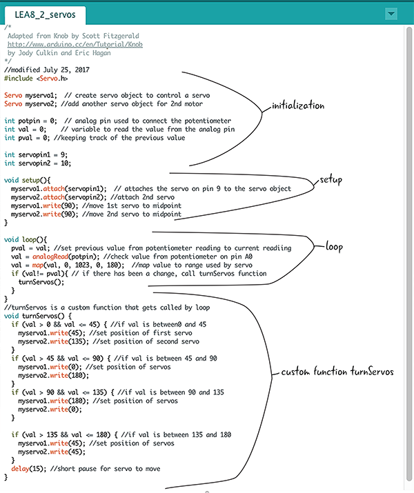
Figure 8-27: The LEA8_2_servos sketch annotated
Some of the comments have been moved in the code breakdowns for legibility.
Initialization
As we’ve said, the initialization section is quite similar to that section in LEA8_Knob. There are a couple of additions: you’re including a variable for the second servo object, and you’re storing the pin numbers that the servos are attached to in variables. You’re also adding a variable (pval) to store the previous value.

The setup() Function in LEA8_2_servos
The setup() function has a couple of changes from the LEA8_Knob sketch. You’re attaching the servo objects to the pins, using the variables servopin1 and servopin2. Then you’re using the write() function of the Servo library to move the first servo to midpoint, followed by moving the second servo to midpoint using the write() function again.

Overview of the loop() Code
In the loop() code, the first line saves the previous value read from the potentiometer into the variable pval. You then read the current value on the potentiometer and map it. Finally, you use a conditional statement to check to see if val is not equal to pval—in other words, check to see if there has been a change in the pin reading. If there has been a change, you call the turnServos() function.
You’ll notice a few things you haven’t seen before in this code. Let’s break it down.

We use a conditional statement to compare the previous value read from the potentiometer to the new value read. This conditional uses a comparison operator: the symbols !=. This operator is used to compare two values, and if one value is not equal to the other, it evaluates to true. (Table 8-1 covered these comparison operators and what each means.)

If there has been a change, the turnServos() function is called. turnServos() is a custom function, the topic of our next section.
Creating a Custom Function
We’ve introduced another new code concept in the updated servo code: custom functions. Why would you want to make your own functions? First let’s quickly review what a function is.
You have used many Arduino functions: delay(), digitalWrite(), and analogRead() are all functions used to perform some specific task with the Uno. You have written most of your code inside the setup() and loop() functions for your sketches.
What is the advantage to writing your own functions? You can group together actions outside of your loop() code and call this new function only when you want those actions to happen. It makes your code more legible and easier to understand.
What does the line of code turnServos(); do? It’s the call to the custom function you wrote. As you’ve seen, it will be called if there has been a change to the variable val—in other words, if someone has turned the potentiometer. turnServos() will only happen when the value of the potentiometer has been changed and not every time the Arduino goes through the loop() function.
What does your turnServos() function look like? First, it starts with void. This is followed by turnServos, which is the name of the function, followed by parentheses and an opening curly brace. The instructions to be executed when turnServos() gets called follow, and the last line contains only a closing curly brace.

Creating a custom function is called declaring a function, and it follows a few rules in the Arduino programming language.

Next you see a set of parentheses. Some functions have parameters or information that will be passed into the function as arguments when the function is called. These are placed inside the parentheses. Since turnServos() doesn’t have any parameters, the parentheses are empty. The parentheses are followed by an opening curly brace, the punctuation you have used before to mark out a block of code.
This discussion about function declaration must seem familiar, because you have seen some of these conventions used before. Where? In setup() and loop()! The difference is that now you are creating and naming the function yourself.
You can write your own functions at any time, and your functions can incorporate any Arduino-compatible code.
Calling a Custom Function
When you want to invoke a function, you call that function. The call to your custom function is inside loop(). The call is simply the name of the function followed by parentheses and a semicolon.

You’ve been making calls to the built-in Arduino functions since you uploaded your first sketch. The functions you’ve used have usually had parameters, so you passed in arguments inside the parentheses. When you called the delay() function, for example, you passed in the amount of time in milliseconds that you wanted the delay to last.

Custom functions can be quite powerful by letting you extend the functionality of your sketches. Our discussion here is limited—it is meant to give you an introduction to the concept and the general rules for creating them. You will undoubtedly explore more on your own.
Inside turnServos()
You know that turnServos() is going to turn your motors, but how? It is positioning both flags in a pattern based on how far the potentiometer is turned; sometimes they are opposite each other, and sometimes they are parallel. The code consists of a series of conditional statements. Let’s look closely at the first one.
In this conditional, it is testing for two conditions. Is val greater than 0 and is val also less than or equal to 45? The value of val must be a number between 0 and 45 for the instructions inside the if statement to be executed.

The symbols && are an example of a Boolean operator. In this case, both the first and second conditions must be true in order for the servo positions to be set.
Boolean Operators
Boolean operators allow you to make complicated evaluations when trying to decide what actions should be taken. Table 8-3 lists the Boolean operators and what they mean and includes an example for each.
Table 8-3: Boolean operators
| Boolean operator | What it means | Example | What the example means |
&& | logical and | if (a>0 && b<10) | Evaluates to true if both conditions are true |
|| | logical or | if (a>0 || b<10) | Evaluates to true if either condition is true |
! | not | if (!a) | Evaluates to true if a is false |
The turnServo() Function and Boolean Operators
Let’s take a look at the first if statement in turnServos() again. What happens if val is a number between 0 and 45? The first servo motor turns to a position of 45 degrees and the second servo motor turns to a position of 135 degrees. You know this because both of the servo object write() functions will be called and move myservo1 and myservo2 to the desired position.

The three other conditional statements in turnServos() work in a similar manner—testing the value of val (how far the potentiometer has been turned), and whether it is between a particular range of numbers, the Arduino will then turn each of the servo motors to their new position specified by the turnServos() function.
Now that you’ve written the sketch, make sure you’ve saved it (as LEA8_2_servos) if you haven’t already done so. Click the Verify button to check for errors, and if it is error free, click the Upload button. Your flags will change positions as you turn the potentiometer (Figure 8-28).

Figure 8-28: Waving two flags
Summary
Our primary focus in this chapter has been to show you how to use servo motors. Servo motors are versatile for many Arduino projects, since a servo can easily be run automatically, as in the Sweep sketch, or can be controlled by a sensor or switch, as in the Knob sketch.
We discussed a number of important programming concepts in this chapter. You learned about libraries, and you used the Servo library to give your Arduino access to a number of servo functions that make it easier to control the servo motors.
We also showed you how to use for loops to set your servos to different positions. And you learned about using comparison, compound, and Boolean operators in your code. You’ll find the LEA8_2_servos sketch here: github.com/arduinotogo/LEA/blob/master/LEA8_2_servos.ino.