
6
Switches, LEDs, and More
In this chapter, you’re going to learn how to make your projects interactive, first by adding a button to turn an LED on and off. Then, you’ll attach a speaker to your Arduino and control both sound and light with your sketch. Finally, you’ll add two more buttons, in the process of building a keyboard instrument on which you can play simple tunes. Throughout these projects, you’ll learn more about programming the Arduino. To complete the projects in this chapter, you need to have the Arduino IDE installed, know how to connect a breadboard to your Arduino, and be familiar with writing a sketch and uploading it to your Arduino.
Interactivity!
In Chapter 4, “Programming the Arduino,” you saw how to connect the Arduino to a breadboard to build a circuit that lit up an LED in an SOS pattern. The LED turned on and off, over and over and over again, always in the same pattern. Wouldn’t it be great if you could build a circuit that would respond to the user’s action?
You’ll do just that in this chapter by building a mini-keyboard instrument with three buttons, a speaker, and an LED. The speaker will play a different tone, depending on which button you push, so you can play a tune. And the LED will turn on whenever you push any of the buttons. We’ll start with a circuit with an LED and a button and build on that. Figure 6-1 is a preview of what the finished circuit will look like.
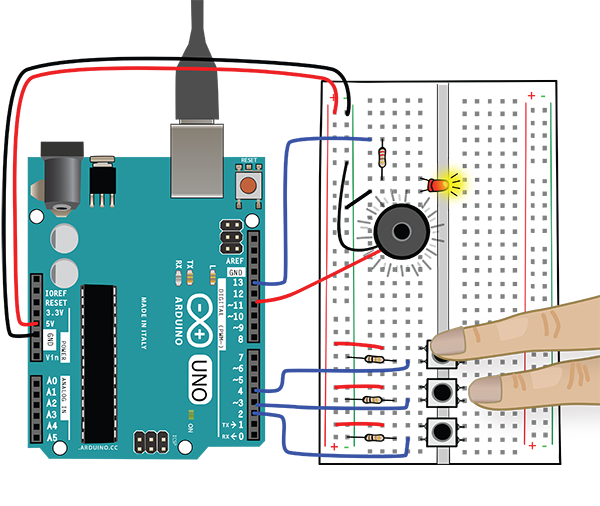
Figure 6-1: Three-tone button keyboard
Just as in Chapter 4, our project will consist of an Arduino and breadboard circuit with code written in the Arduino IDE. We’ll go over building the circuit and all of the code in the sketch step by step. In this chapter, you will also learn a bit more about reading schematics.


This project uses digital inputs and outputs. You used a digital output, an LED, in the last chapter. Before we start to build, let’s look more closely at what we mean by digital input and output.
Digital Inputs and Outputs Overview
Think about your computer: how do you get information into it? You may use a mouse, and you probably use a keyboard. Keyboards and mice are both examples of inputs (Figure 6-2). You can attach many different types of inputs to your Arduino. In this chapter you will attach buttons to the Arduino as inputs.

Figure 6-2: Common inputs
What do we mean by output? Again, think about your computer. You might have speakers attached to it, or a monitor or printer. Those are all examples of output devices (Figure 6-3). An Arduino can have many different types of outputs attached to it. In fact, you have already used an output device with the Arduino: the LED you connected to it in the last chapter.
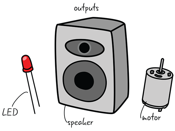
Figure 6-3: Common outputs
For now, think of digital inputs and outputs as components that have only two possible states: on or off. Inputs send messages to the computer. Outputs receive messages from the computer. We will explain this in more detail later in the chapter.
Before you start building your circuit, let’s look at the schematics for a button or switches. Doing so will help you understand how digital input works.
Switches
There are a million different ways to trigger electronic devices or turn something on. Switches and similar on/off devices activate televisions, music equipment, lights—even your kitchen appliances! How does a switch work?
All switches work on the same basic principle: it either “closes the circuit” and turns something on, or “opens the circuit” and turns something off. When the switch is closed, electricity can flow through; it cannot flow through when the switch is open. Figure 6-4 illustrates how this works.

Figure 6-4: Switch diagrams
Like all digital inputs, as you saw earlier, switches have only two possible states: on and off. In the Arduino IDE, on and off (respectively) are equivalent to HIGH and LOW. (Remember how, in the SOS circuit in Chapter 4, the light turned on when you set it to HIGH and off when you set it to LOW.) Each key on a keyboard is actually a switch, set in the off position until pressed down, when it goes to on.
Buttons are one type of switch. For our circuit, we will use a momentary pushbutton switch, which closes and completes the circuit when you press it. As soon as you let go, the switch opens again and the circuit is no longer complete.
Digital Input: Add a Button
Let’s get our parts together to start building a circuit with a button.
You’ll need the following:
- 1 LED
- 1 220-ohm resistor (red, red, brown, gold)
- 1 10 kΩ resistor (brown, black, orange, gold)
- 1 momentary pushbutton switch
- Jumper wires
- Breadboard
- Arduino Uno
- USB A-B cable
- Computer with Arduino IDE
Figure 6-5 shows a preview of what the circuit will look like when it’s built, as well as the schematic. Since the schematic is a bit different from those we have seen before (it includes some new symbols), we will take a closer look at it.
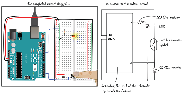
Figure 6-5: LED button circuit
Understanding More Complex Schematics
The schematic for this circuit follows a couple of conventions that you haven’t seen before.
At the bottom of this schematic is a small circle indicating that the cathode of the LED (remember: the cathode is the LED’s short lead or negative side) on Pin 13 is connected to the same ground as the resistor that is attached to one end of the switch. A filled circle is often used in schematics to indicate connection points.
As schematics become more complex, you sometimes have to run lines that are not connected over each other. To indicate that these lines are not connected, we’ll draw a little loop like the one on the right side of Figure 6-6.

Figure 6-6: Schematic diagram
Building the Button Circuit
Before you add the button to the circuit, you have to rebuild the circuit you used with the LEA4_Blink sketch in Chapter 4, shown again in Figure 6-7. Here’s a quick overview of how to do that. Follow along and check each step as you go:
- Attach the power and ground from the Arduino to the power and ground buses on the breadboard.
- Connect a jumper from Pin 13 on the Arduino to a row of tie points on the breadboard.
- Connect a 220-ohm resistor to the same row of tie points as Pin 13.
- Connect the anode (long leg) of the LED to the other end of resistor, and jump the cathode (short leg) of the LED to the ground bus.
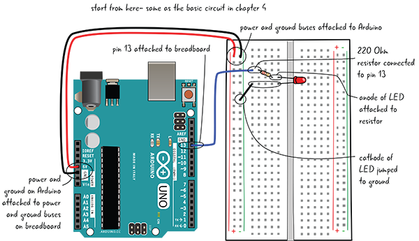
Figure 6-7: Reviewing the basic circuit from Chapter 4
Now that you have the basic circuit assembled, you’ll add a button. You’ve looked at the schematic for a button, but before you put the button in the breadboard, let’s look at how the button is constructed.
Adding the Button
The button you’re going to add is a pushbutton switch (a.k.a. a momentary switch). While you are pressing the button, the LED will turn on, and as soon as you lift your finger, the LED will turn off (Figure 6-8). This type of button gets its name from just being toggled for the moment.

Figure 6-8: Button diagrams
When the button is pressed, the circuit is closed, and electricity can flow through it, like the diagram you saw earlier in this chapter.
This button actually contains two separate switches (that’s why it has four pins sticking out of it). Both close when you press the button down. Your circuit will use only one side of the button.
Remember the trench that runs down the middle of the breadboard? (You learned about it in Chapter 3, “Meet the Circuit.”) Your button is going to be placed across the trench, with two pins inserted into the row of tie points on each side. The button will only fit across the trench in one orientation. Placing your button across the trench ensures that it is oriented correctly, with each pin connected to a separate and discrete row of tie points (Figure 6-9). As long as the button fits across the trench, the button direction will not matter.
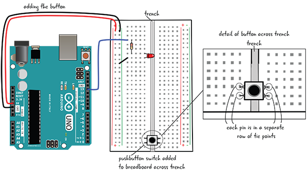
Figure 6-9: Adding the button to your breadboard
Connecting the Button to Power, a Resistor, and Ground
Let’s continue wiring the button. Add a red jumper that connects the power bus (the one with the “+” sign) on the breadboard to the top-left side of the button (Figure 6-10).
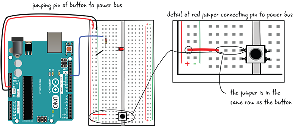
Figure 6-10: Adding the first jumper wire
Next, attach a 10 kΩ resistor (colored brown, black, orange, gold). Attach one of the resistor’s leads to the button, and the other lead to the ground bus (the one with the “–” sign), as shown in Figure 6-11.

Figure 6-11: Adding the resistor for the button
Attach the Button to an Arduino Pin and Upload a Sketch
Finally, you’ll attach a jumper to Pin 2 on the Arduino. This jumper will be attached to the 10 kΩ resistor that is attached to the ground bus. As you can see in Figure 6-12, the resistor, the jumper to the pin, and one of the pins of the button should all be in the same row of tie points. The jumper wire also needs to be in between the resistor and the button.

Figure 6-12: Adding the jumper to the digital pin
The button is all hooked up. Now that the Arduino is attached to the breadboard and the button is wired up, hook up the Arduino to your computer so you can upload a sketch that will control the behavior of the button and the LED.
Open, Save, Verify, and Upload
Attach your computer to the Arduino with the USB cable so you can upload the Button sketch. This is one of the example sketches that comes with the Arduino IDE.
- Launch the Arduino IDE, and then open the Button sketch by choosing File > Examples > 0.2 Digital > Button.
- Save the button sketch as LEA6_Button.
- Click the Verify button first to make sure your code is okay.
- Click the Upload button to upload your code to the Arduino. This is all shown in Figure 6-13.

Figure 6-13: Procedure for getting code onto the Arduino
Turn the LED On and Off
Now when you press the button, the LED will light up, as you can see in Figure 6-14.
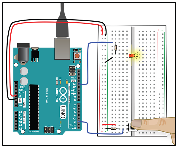
Figure 6-14: Press the button and the LED lights up.
You’ve built the circuit and looked at the schematic. Now let’s examine the code for LEA6_Button in detail.
Looking at the Sketch: Variables
Here’s the code for the LEA6_Button sketch. We’ll step through the details over the next few pages. We’ve removed the code’s starting comments for the sake of brevity.


Initializing Our Code and Variables
LEA6_Button is different from our LEA4_Blink sketch in that there is code that happens before the setup() function. This initial code is aptly called initialization code—code at the very top of a sketch where you declare values that you want to have access to throughout your sketch. Let’s take a look at this sketch’s three lines of initialization code:

All three lines of codes look similar; they all have some words on the left and numbers on the right with an equals sign in the middle. But what do they do? To help you understand this section of code, we’ll introduce a new programming concept: variables.
What Is a Variable?
In the simplest terms, a variable is a place to store a specific value and give it a useful name. Think of a variable as a container that holds a value. If you’ve taken algebra, you’re familiar with variables. Remember equations where you were told things like “if x = 1”?
Variables can hold different types of values. For now we will look at variables that hold integers.
In the following code line, we are both declaring and assigning a variable. Declaring a variable means to give it a name, and assigning the variable gives it a value. You can declare variables without giving them a value, but you can’t give a value to something you have not yet declared.

Declaring Variables
A line of code that defines a variable is called a variable declaration. Often Arduino code will also include a variable assignment. Variable declarations and assignments are not structured the same in all programming languages—we are looking only at how variables are declared in the Arduino programming language.
In the Arduino language, all variable declarations and assignments have at least four different parts: the type of data the variable contains, the variable’s name, an equals sign, and the actual value you wish to set for the variable. (Variables can have more than four parts; you’ll learn about a fifth part momentarily.)

In this example, you are putting the value 0 into a variable with the name buttonState that has a type of int, which stands for integer. Let’s look at all the parts of that declaration in detail. We’ll start with the name, and then look at the value.
Variable Name
The name part of the declaration determines how you refer to your variable through the rest of your sketch. There are a few rules for selecting names: a variable name can’t start with a number, can’t have any spaces in it, and can’t be a word that the Arduino language already uses for another purpose (for example, we can’t name a variable “delay,” since that term is already reserved by the Arduino language). There should be only one variable with a particular name for each sketch. It is considered best practice to name your variables something that indicates their purpose.

Variable Value
The value part of the declaration is what is stored in the variable. In this example you have an integer value of 0, which corresponds to the state, or voltage value, of our pin. Values are set using one = (equals sign), which says that anywhere you see this variable’s name (buttonState), it means “Use the value 0” or “You are assigning the value 0 to this variable.”

Variable Type
type sets what type of information you can save within your variable. In the declaration we’re examining, int stands for integer, which means you can save only values that are whole numbers. Not all languages have typed variables, but in the Arduino language, you must declare the type of each variable in your sketch. Other types include float, string, character, and Boolean; you can learn more about variables types at arduino.cc/en/Reference/VariableDeclaration.

Now that you know about the four parts required in variable declaration, let’s examine one optional part that’s used in a couple of variable declarations in our sketch: the qualifier.
Variable Qualifiers
Some variables also have a qualifier, which determines whether you can change the value of the variable after you create it. The qualifier const sets your variable to have a permanent value when you run the sketch. In this context, const stands for constant. Here’s an example from our sketch:

It may seem a little strange to think of a constant variable, but remember that setting a variable just means to keep track of a value with a name. When you plug the wires into the pins of your Arduino, the pin numbers are not going to change. Since the value of the variable isn’t going to change, you add const to your declaration, which makes it clear that this is a constant variable.
As you can see from the following initialization code, our sketch contains two constant variables and one variable that can change:

setup() for LEA6_Button
Now that we’ve looked at the LEA6_Button sketch’s initialization code, let’s move on to its setup() function:

The setup() function for the LEA6_Button sketch has only two lines of code. Similar to the code in Chapter 4, you’re setting a pin to be an output using the pinMode() function. This time, however, you’re using the variable ledPin to stand in for the number 13. You’re also using pinMode() to set a different pin with value buttonPin as an input. These are two of the three variables that you created in the sketch’s initialization code. Naming your variables gives you a way to refer to numbers you need in your sketch in a meaningful way and makes your code easier to read.
Let’s take a closer look at what we mean by digital input.
Digital Input Refresher
Let’s say that you’re arriving at a friend’s house when your friend calls and asks you to look through the window at a light. Your friend then asks, “Is the light on?” Your job is to tell the friend, “Yes, the light is on” or “No, the light is off.” That’s exactly what a digital input does: it reports whether the light is on or off (Figure 6-15).

Figure 6-15: Digital input states
In digital inputs, there are only two possible states: HIGH and LOW, which you can think of as on (HIGH) or off (LOW). Digital inputs measure whether something is on (in a HIGH state) or off (in a LOW state). HIGH/on is also equal to 1 and LOW/off is equal to 0. We can use the digital pins on the Arduino to check on buttons and switches to see whether or not they have been triggered or pressed.
Why Three Different Ways to Say the Same Thing?
If HIGH, 1, and on are all equivalent (as are LOW, 0, and off), why are there multiple ways to say the same thing? This can be confusing.
Each value talks about a different aspect of our Arduino project:
- On and off refer to what we see happening in the world. For example, is the LED lit or not? We don’t use the terms on and off in our code for the Arduino—only in our general discussions.
- 1 and 0 are integer variable values that represent on and off, respectively. We use 1 or 0 when we are initializing variables in our code. You saw an example of this in our sketch’s initialization code, which includes the line
int buttonState = 0;. This line tells the Arduino that the button is initially off. HIGHandLOWrefer to the electrical state of the pin: is the pin providing 5 volts or is it acting as 0v (ground)? In the Arduino programming language,HIGHandLOWare used to set or to read the state of a pin (viadigitalWrite()anddigitalRead()functions).- 1’s and 0’s are part of the binary language that computers speak.
HIGHandLOWmeans 1 and 0 to computers, including our Arduino.HIGHandLOWmake the code slightly easier for humans to read, and they are used when we are using thedigitalWrite()anddigitalRead()functions. You’ll use 0 and 1 when you are creating new variables.
Looking at the Sketch: Conditional Statements
Now that you understand what digital inputs do, let’s take a look at the LEA6_Button sketch’s loop() code.

Exploring the loop()
In the first line of the LEA6_Button sketch’s loop() section, the Arduino uses a function called digitalRead() to check whether a pin is on or off. In this case, you are checking the pin represented by your buttonPin variable, so you are evaluating the state of Pin 2. The results of your digitalRead() function will be either a value of 1 (HIGH) or 0 (LOW). You then set your variable named buttonState to this value.

The next part of the loop() code gives you another new programming concept: the use of conditional statements.
What Is a Conditional Statement?
Conditional statements are a powerful way to change what happens within your code depending on conditions you specify, such as whether a button is on or off. You have experienced the use of conditional statements in everyday language, as shown in Figure 6-16.

Figure 6-16: Conditional statements in English
Conditionals in programming work the same way. They have three basic parts: the if, the expression you are evaluating, and what you want to happen if our statement is true. Let’s take a look at conditional statements in our loop() code.
The first part of the conditional statement within the loop() code for LEA6_Button is shown here. In some sketches, this could be your whole conditional statement; ours happens to have a second part—you’ll learn about it soon.

This part of the conditional statement includes the if, the expression you are evaluating, and what happens if your expression is true. Everything that will happen, if the statement is true, is contained within a set of brackets. You, as the programmer, get to tell the program what to do if certain situations happen.
Conditional Statements in loop()
Conditional statements start with an if. The if tells the computer to evaluate the next expression.

The next part of the conditional statement is the condition to be evaluated. This is a section of code that the Arduino has to assess for truth. “True” in a programming context means that the condition is logically valid. For example, the English statement “One is equal to one” doesn’t tell us anything interesting, but it is true. The nonsensical statement “Two plus two equals five” is false. You will see various types of conditional statements throughout the book that evaluate what is happening with your Arduino and the rest of the circuit.
In the case of this sketch, the code is trying to evaluate whether the button is currently pressed. (Remember, pressed means “on,” which is the same as HIGH in the Arduino programming language.) To test whether a value is equal to another value, you use two = signs, or ==.

The last part is the “true” code block, the commands that are run if the condition is true. There is no limit to the number of actions you can include inside the true code block, as long as they are all contained within the brackets. In this case, the code block will turn on the LED attached to the ledPin, also known as Pin 13.

Conditional Statements: else
What happens if the button is not pressed? For this conditional statement, there is an else clause, which handles any events that happen when the statement is not true. else is helpful for dealing with cases where the if statement is false, but it is not required for every conditional statement. Some conditionals have an else, and some do not. If this conditional didn’t have an else, then if the condition you’re evaluating were false, nothing would happen.
For your button code, the else statement can also be broken down into a simple English statement: “If the button is not pressed, then turn off the light.”

Table 6-1 shows a quick summary of the conditional statement we just examined.
Table 6-1: Conditional statement in LEA6_Button
| What is happening in the circuit? | Condition to be evaluated | Truth value | Result |
| Button is pressed | if (buttonState == HIGH) | true | Turns LED on |
| Button is not pressed | if (buttonState == HIGH) | false | Turns LED off |
Now that you’ve connected your button and made it turn the LED on and off, you are ready to make your circuit more interesting. Let’s add a speaker, and then add some code so that the speaker plays a tone when you press the button. First we’ll show you how to add the speaker to the breadboard.
Add a Speaker and Adjust the Code
In this circuit, the button, LED, resistors, and jumpers will stay in the same place. You are simply adding a speaker; everything else remains the same (Figure 6-17).
Part to add:
- 1 8-ohm speaker
As always, before you attach the speaker, make sure your computer is not connected to the Arduino. Attach one end of the speaker to Pin 11 on the Arduino and the other end to the ground bus (Figure 6-18). It doesn’t matter which end you connect where; like a resistor, the speaker does not have an orientation. The colors of your speaker wire may vary, but the speaker does not have a direction.
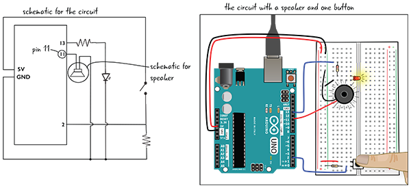
Figure 6-17: A speaker added to the circuit
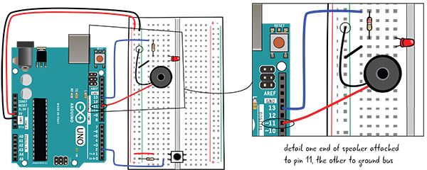
Figure 6-18: Adding the speaker
That’s all there is to adding a speaker. Now you are ready to adjust your code.
Adding Code for the Speaker
Now that you’ve wired up the speaker, you will adjust the code. First, save the sketch as a new sketch named LEA6_1_tonebutton.
You’re going to add a line of code to the sketch’s initialization section and add a variable for the speaker pin.

Let’s look at the new line of code more closely. You can see that it is like your other variable declarations: there is a qualifier, a type, a name, and a value. Remember, you use the const qualifier, which stands for constant, when you have a variable that has a value that will not change.

Adjusting setup()
What do you think you will have to adjust in the sketch’s setup() section? Remember that setup() is where you state whether the circuit’s various components are inputs or outputs.
What is the speaker? An output. So you’ll add a line of code that will declare that the pin the speaker is attached to is an output. Because you made a variable to hold that value, you will use it when you declare the pin an output.

Here’s a closer look at this new line of setup() code:

On to loop()!
Adjusting loop()
As you have seen, loop() has the code that reads whether or not the button is pressed and then uses a conditional to direct the Arduino to do something based on that information. Now you will use the Arduino functions tone() and noTone() inside the conditional. tone() will generate a note or tone; noTone() will stop it from being played. Let’s look at all of the loop() code first, and then explore tone() and noTone() more closely.

As we said, tone() will generate a note or tone that can play through the speaker you just attached. When you use the tone() function, you need to tell Arduino on which pin to generate a tone and what note to play. It makes sense that you want to generate a note on the pin that has the speaker attached.

Let’s take a more in-depth look at the tone() and noTone() functions.
tone() and noTone() Up Close
What does 330 mean? You know it means the note the speaker will play, but how do you arrive at that number? The Arduino generates sound waves that are measured in hertz; 330 is the hertz value of the note you want your circuit to play.

In musical circles, this note is known as an E. From now on, when we mention the tone() function, we will say that it is generating a note. Figure 6-19 shows some of the possible note values.

Figure 6-19: Note chart
Now let’s look at noTone(). This function stops the sound from being played on the pin specified. In this case, that’s speakerPin, which stores the value of the pin that has the speaker attached to it. If you leave out noTone(), then your note will play continuously once you press the button the first time.

Add the tone() and noTone() functions to your code, save your sketch, and then upload. Now when you press the button, you’ll hear a note playing from the speaker, as well as see the LED turn on.
We said earlier that we would explain what’s inside the parentheses in functions. For example, in the tone() function, what do speakerPin and 330 mean? Those values are called arguments. Let’s take a look at them now.
Arguments
You’ve used a number of Arduino functions in this book so far, from pinMode() to digitalWrite(). You may have also noticed that most of the functions require something to be placed within the parentheses, often some combination of numbers and words. The values placed inside the function are called arguments.

Arguments tell your Arduino function important information, such as which pins are used as inputs. Different functions often have a different number of arguments. digitalWrite() has two arguments—the pin number and the value—whereas the Arduino delay() function has only a single argument—how many milliseconds to pause the program. Some functions won’t need any arguments, whereas others will require several. Let’s look at the tone() and noTone() functions and how arguments work with them.
In the tone() function, two arguments are passed in: the pin that the speaker is attached to (in this case, the variable speakerPin) and the value of the note. Note that the argument values are separated by a comma.

The noTone() function has one argument: the pin that the speaker is attached to (again, the variable speakerPin).

Some functions have no arguments, whereas others have many. In some functions, not all of the arguments are required. You’ll learn more about functions and arguments in later chapters.
Next, you’ll add a second button to your tone button keyboard so you can play more than one note.
Add Two More Buttons and Adjust the Code
You are going to add another button to your circuit so you can play a two-note tune on your mini-keyboard instrument (Figure 6-20). You will need another button, another 10 kΩ resistor, and more jumpers. Remember to unplug your Arduino from your computer before you add to the circuit.
Parts to add:
- 1 momentary pushbutton switch
- 1 10 kΩ resistor (brown, black, orange, gold)
- Jumper wires
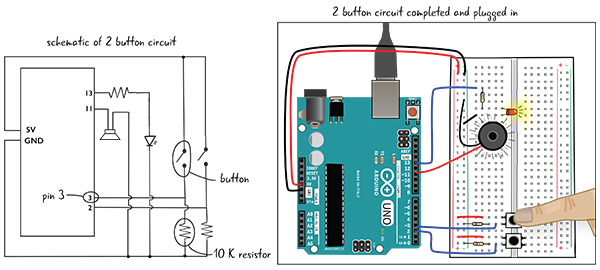
Figure 6-20: Two-button circuit
The configuration of this button will be very similar to the first button you placed in the circuit, except that the new button will be attached to a different pin on the Arduino (Figure 6-21).
Place the new button across the trench. Use a jumper wire to connect the button’s top-left pin to the power bus. Attach one lead of the 10 kΩ resistor to ground and the other lead to the lower-left pin of the button. Finally, attach Pin 3 to the lower-left pin of the button and one end of the 10 kΩ resistor with a jumper wire.
Now that you’ve added the second button, it’s time to adjust the code in the sketch.
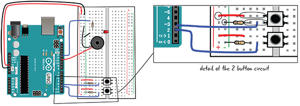
Figure 6-21: Attaching the second button
Editing LEA6_2_tonebuttons
First, save your sketch as LEA6_2_tonebuttons. You will edit your code, adding the lines that are marked in bold on the next couple of pages.
Initialization Code Adjustments
Here is the initialization code updated with two new variables. One is set to the number of the pin you attached to the second button (3); the other will hold the state of that button, and it is initially set to 0.

setup() Code Adjustments
The following graphic shows the setup() code again, edited to account for your second button. You use the pinMode() function again, this time to set buttonPin2 (which you set to 3 in the initialization code) as an input.

Next, let’s look at the loop() code and see what you need to add.
Adjusting the loop() Code: else if
You can see that you are reading the value of buttonPin2 (either 1 for on or 0 for off) with the digitalRead() function and storing it in the variable buttonState2.
You also have to add a new section inside your if statement—what is known as an else if. When your if statement is being evaluated, it will check for the first condition after the if to see whether that condition is true or false. As you saw earlier, if the first condition is true (in other words, if button 1 is currently pressed), then the speaker will play a note at 330 hertz. But if the first condition is false (in other words, if button 1 is not currently pressed), then the Arduino will move on to the else if code to determine whether the statement following the else if is true or false. If it is true (in other words, if button 2 is currently pressed), then the Arduino will follow the instructions inside the curly braces.

Let’s look at each line of the else if.
First, else if tells us that the Arduino is going to test for another condition. It is testing whether buttonState2 is HIGH—in other words, is the button at Pin 3 currently being pressed?

You’ve seen the code in the next line of the else if block before; it sets the pin attached to the LED to HIGH so that the LED turns on.

And here’s the last line in the else if block. It uses the tone() function to play a note on the speaker. This time, the note is 294 hertz—slightly lower than the note played by the first button.

The following graphic shows the whole block of the else if code again. Note that the parentheses surround the code that describes the condition being tested, and the curly brackets surround what you want to do if the condition is true.

To test your code, attach your computer to your Arduino, save your code, verify it, and upload in to the Arduino.
Now you can play two different notes on your two-button keyboard.
Adding the Third Button
Now you’re going to add a third and final button to the circuit (Figure 6-22). Be sure to unplug your Arduino from your computer before adding this button!
Parts to add:
- 1 momentary pushbutton switch
- 1 10 kΩ resistor (brown, black, orange, gold)
- Jumper wires

Figure 6-22: Three-button circuit
Place the button across the trench above the other two buttons. Use a jumper to connect the button’s top-left pin to the power bus. Attach one lead of the 10 kΩ resistor to ground and the other lead to the lower-left pin of the button. Finally, attach Pin 4 to the lower-left pin of the button and one end of the 10 kΩ resistor (Figure 6-23).
Now that you’ve added the third button to the circuit, it’s time to adjust the sketch.
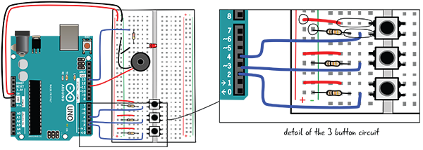
Figure 6-23: Adding the third button
Editing the LEA6_3_tonebuttons Sketch
Save your sketch as LEA6_3_tonebuttons, and we’ll look at the code you have to adjust. This will be very similar to the adjustments you made to the previous sketch when you added the second button. Follow along and edit your sketch to match the following code.
Initialization Code Edits
You are attaching the third button to Pin 4. You’re also adding a variable called buttonState3, which holds the value that indicates whether or not the pin is being pressed (1 or 0, HIGH or LOW, on or off).

setup() Code Edits
In our setup() code, we set the variable buttonPin3 (which holds the value 4 to indicate pin 4) to an INPUT. All three of our buttons have now been set as INPUTs.

Three-Button “Instrument” loop() Function
The updated loop() function is shown next. It reads the state of buttonPin3 and stores it in buttonState3. It also has an additional else if statement, which tests to see whether the third button is being pressed, and if so, plays a note (one slightly lower than the note for button 2) and lights the LED.

Your code can now respond when you press each of the three buttons.
Play Your Mini-Keyboard Instrument
You’ve written your code and adjusted your circuit. Your three-button mini-keyboard instrument should now work. To take it for a spin, attach your computer to your Arduino, save your code, verify it, upload it to the Arduino, and then press the buttons. Remember to press one button at a time, since the speaker can play only one note at a time.
Before we move on to look at how some of the components are working in this circuit, we’ll briefly review what you’ve learned about writing code while building this project.
Reviewing Electronic and Code Concepts
You learned a few new, and very important, programming concepts in this chapter. These concepts are critical to writing code in all programming languages, though the details might be a little different depending on the language. Let’s look once more at variables and conditionals.
Variables
A variable is a container in your code that can hold different values.

Conditional Statements
A conditional statement evaluates a condition and executes instructions if that condition is true. If the conditional statement contains an optional else if or else block, then it can test for multiple conditions, and it sometimes tells the code to do something if the conditions are not true.

Let’s take a quick look at how the electronic components you used in this chapter work in a circuit.
How Does the Button Work?
The default, unpressed state of the button is open, meaning electricity can’t flow through it. In order for electricity to flow through your button, it must be pressed down, making a connection between the pins (Figure 6-24). When you read the value on the pin that is attached to the button, you will see that it is HIGH.

Figure 6-24: Pushing the button
There is nothing attached to the pins on the other side of the trench, but the pins on that side of the trench are also connected when the button is pressed (Figure 6-25).

Figure 6-25: How a switch functions
How Does the Speaker Play Different Notes?
The tone() function built into the Arduino knows how to change the power provided by your digital pin to create different notes from your speaker. Without getting too technical, the note value you include in your tone() function tells the Arduino how to rapidly change the voltage to create different notes (Figure 6-26).
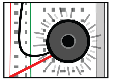
Figure 6-26: A change in voltage to the speaker will play different notes.
Summary
This chapter taught you more about programming. You learned what a variable is and how to use it, and how to use conditional statements to control the flow of your program. You also learned more about digital output and how to add a digital input to your circuit to make your project interactive. You can download the code here: github.com/arduinotogo/LEA/blob/master/LEA6_3_toneButtons.ino.
In the next chapter, we will show you how to attach analog sensors or other inputs to a circuit and use the information you gather from them to do more with your output components than turn them on and off.