
Another very common type of object used in automation and IoT is the actuator. While the sensor is used to sense physical magnitudes or events, an actuator is used to control events or act with the physical world. We will create a simple actuator that can be run on a standalone Raspberry Pi. This actuator will have eight digital outputs and one alarm output. The actuator will not have any control logic in it by itself. Instead, interfaces will be published, thereby making it possible for controllers to use the actuator for their own purposes.
Our actuator prototype will control eight digital outputs and one alarm output:
- Each one of the digital output is connected to a 160 Ω resistor and a red LED to ground. If the output is high, the LED is turned on. We have connected the LEDs to the GPIO pins in this order: 18, 4, 17, 27, 22, 25, 24, and 23. If Raspberry Pi R1 is used, GPIO pin 27 should be renumbered to 21.
- For the alarm output, we connect a speaker to GPIO pin 7 (CE1) and then to ground. We also add a connection from GPIO 8 (CE0), a 160 Ω resistor to a green LED, and then to ground. The green LED will show when the application is being executed.
The actuator project can be better understood with the following circuit diagram:
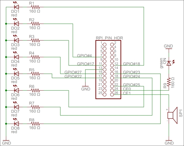
A circuit diagram for the actuator project
All the hardware interfaces except the alarm output are simple digital outputs. They can be controlled by the DigitalOutput class. The alarm output will control the speaker through a square wave signal that will be output on GPIO pin 7 using the SoftwarePwm class, which outputs a pulse-width-modulated square signal on one or more digital outputs. The SoftwarePwm class will only be created when the output is active. When not active, the pin will be left as a digital input.
The declarations look as follows:
private static DigitalOutput executionLed =
new DigitalOutput (8, true);
private static SoftwarePwm alarmOutput = null;
private static Thread alarmThread = null;
private static DigitalOutput[] digitalOutputs = new DigitalOutput[]
 {
    new DigitalOutput (18, false),
    new DigitalOutput (4, false),
    new DigitalOutput (17, false),
    new DigitalOutput (27, false),// pin 21 on RaspberryPi R1
    new DigitalOutput (22, false),
    new DigitalOutput (25, false),
    new DigitalOutput (24, false),
    new DigitalOutput (23, false)
  };
Digital output is controlled using the objects in the digitalOutputs array directly. The alarm is controlled by calling the AlarmOn() and AlarmOff()methods.