As you have seen, all endpoints in MQTT connect to the broker in the same way as MQTT clients. The same is true for the controller, which subscribes to the information published by the sensor and publishes commands to the actuator, as shown in the following code:
Client = new MqttClient ("iot.eclipse.org", MqttClient.DefaultPort,"LearningIoTController", string.Empty, false);
Client.Open ();
Client.CONNECT (20, true);To handle events from the sensor, we need to register an event handler, as we did for the actuator; this time, we will register it as a lambda function for the sake of simplicity. This means we will provide the code to handle events before we could actually perform the subscription.
Client.OnDataPublished += (Sender, e) =>
{
  string Topic = e.Topic;
  if(!Topic.StartsWith ("Clayster/LearningIoT/Sensor/"))
  return;

  string s = System.Text.Encoding.UTF8.GetString(e.Data);
  PhysicalMagnitude Magnitude;
  bool b;
  Topic = Topic.Substring(28);
  switch(Topic)
  {
    // Topic data to be processed here.
  }
};When a new light value is reported, we make sure to parse it and flag the event, as we have done previously for other protocols. We use the PhysicalMagnitude class defined in Clayster.Library.Math to help us parse a numerical value suffixed by a physical unit:
case "Light":
  if(PhysicalMagnitude.TryParse (s, out Magnitude) && Magnitude.Unit == "%" && Magnitude.Value >= 0 && Magnitude.Value <= 100)
  {
    lightPercent = Magnitude.Value;
    if(!HasLightValue)
    {
      HasLightValue = true;
      if(HasMotionValue)
        hasValues = true;
    }
    CheckControlRules();
  }
  break;
In a similar manner, we parse incoming changes reported by the motion detector and report it to the underlying control logic:
case "Motion":
  if(!string.IsNullOrEmpty(s) && XmlUtilities.TryParseBoolean(s, out b))
  {
    motion = b;
    if(!HasMotionValue)
    {
      HasMotionValue = true;
      if(HasLightValue)
        hasValues = true;
    }
    CheckControlRules();
  }
break;We can now subscribe to the events published by the sensor similar to the way the actuator subscribed to control commands:
Client.SUBSCRIBE(new KeyValuePair<string, MqttQoS> ("Clayster/LearningIoT/Sensor/#", MqttQoS.QoS1_Acknowledged));
Log.Information("Listening on MQTT topic " + "Clayster/LearningIoT/Sensor @ ", EventLevel.Minor,Client.Host + ":" + Client.PortNumber.ToString());Now that we have received sensor data and calculated the desired control actions, all the controller needs to do is publish the corresponding control commands on the topics listened to by the actuator. To highlight the fact that we use binary data in MQTT and control encoding and decoding ourselves, we will first define a UTF-8 encoder that will encode strings to a binary format without using a byte order mark or preamble:
UTF8Encoding Encoder = new UTF8Encoding (false);
The final step is to publish commands as they occur by encoding the corresponding command strings and publishing them on the corresponding command topics. We begin by the command to update the LEDs of the actuator:
switch(WaitHandle.WaitAny(Handles, 1000))
{
  case 0:// Update LEDS
    int i;
    lock(synchObject)
    {
      i = lastLedMask;
    }
    Client.PUBLISH("Clayster/LearningIoT/Actuator/do",Encoder.GetBytes(i.ToString ()), MqttQoS.QoS1_Acknowledged, true);
Even though it is not needed for our immediate control needs, we will also publish individual control commands. Since content is retained by the message broker, content on the topics will be consistent if the actuator reboots and receives the latest control commands from the broker. Since the subtopics do1 to do8 correspond to the bits of the compound subtopic do, we simply loop through the bits in do and publish each one to its corresponding subtopic. This is performed with the following code:
for (int j = 1; j <= 8; j++)
{
  Client.PUBLISH("Clayster/LearningIoT/Actuator/do" + j.ToString (), Encoder.GetBytes ((i & 1).ToString ()), MqttQoS.QoS1_Acknowledged, true);
  i >>= 1;
}
break;We control the alarm output in the same way as we control the LED output. We wait for the event and publish the corresponding control command on the corresponding control topic:
case 1:// Update Alarm
  bool b;
  lock(synchObject)
  {
    b = lastAlarm.Value;
  }
  Client.PUBLISH("Clayster/LearningIoT/Actuator/ao", Encoder.GetBytes (b ? "1" : "0"), MqttQoS.QoS1_Acknowledged, true);
After we publish the control command, we also need to start the SendAlarmMail thread if the alarm is activated:
if(b)
{
  Thread T = new Thread (SendAlarmMail);
  T.Priority = ThreadPriority.BelowNormal;
  T.Name = "SendAlarmMail";
  T.Start ();
}
break;
Finally, we must not forget to update any camera subscriptions we maintain on the UPnP network:
  default:// Timeout
    CheckSubscriptions (30);
    break;
}
Our controller is now ready to operate, together with the sensor and the actuator using MQTT as the control protocol. This means that all the three can reside in separate networks protected by individual firewalls. The only restriction to network topology we have is that any cameras used by the controller need to be in the same local area network as the controller itself.
If we have access to a tool that can be used to visualize MQTT topics, we can monitor how our devices operate. You can find many tools and applications for this purpose at https://github.com/mqtt/mqtt.github.io/wiki/tools.
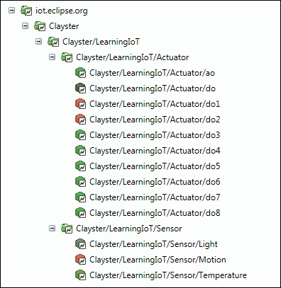
In the following example, visualized by Clayster Management Tool, each topic in the topic tree is visualized as a node. Even if it cannot be seen in the print version of the book, the topics that publish Boolean properties are colored red and green depending on whether 1 or 0 is published. The numerical topics related to the light are colored from black to white, depending on how much light is reported. The temperature on the other hand is colored blue if cold (15 degree Celsius). If warmer, it is blended to green (about 20 degree Celsius) and finally blended to red if hot (25 degree Celsius). Colors here assume it is an in-door temperature we are measuring. A colored version of the image is available for download at the Packt Publishing website.
The topic tree is shown in the following screenshot: