
We are now ready to build our control application. You can build various different kinds of applications on Clayster. Some of these have been listed as follows:
- 10-foot interface applications: These applications are suitable for TVs, smart phones and tablets. They are created by deriving from the
Clayster.AppServer.Infrastructure.Applicationclass. The name emerged from the requirement that the application should be usable from a distance of 10 feet (about 3 meters), like a television set. This, for instance, requires large fonts and buttons, and no windows. The same interface design is suitable for all kinds of touch displays and smart phones. - Web applications: These applications are suitable for display in a browser. These are created by deriving from the
Clayster.AppServer.Infrastructure.WebApplicationclass. The thingk.me service is a web application running on the Clayster platform. - Non-visible services: These services can be implemented, by the
Clayster.Library.Installation.Interfaces.IPluggableModuleinterface. - Custom views: These views for integration with the CMT can be implemented by deriving from
Clayster.Library.Layout.CustomView.
The first two kinds of applications differ in one important regard: Web applications are assumed to be scrollable from the start, while 10-foot interface applications have to adhere to a fixed-size screen.
When creating user interfaces in Clayster, the platform helps the developer by providing them with a powerful rendering engine. Instead of you having to provide a complete end user GUI with client-side code, the rendering engine creates one for you dynamically. Furthermore, the generated GUI will be created for the client currently being used by the user. The rendering engine only takes metadata about the GUI from the application and generates the GUI for the client. In this way, it provides a protective, generative layer between application logic and the end user client in much the same way as the object database handles database communication for the application, by using metadata available in the class definitions of objects that are being persisted.
The rendering pipeline can be simplistically described as follows:
- The client connects to the server.
- An appropriate renderer is selected for the client, based on protocol used to connect to the server and the capabilities of the client. The renderer is selected from a list of available renderers, which themselves are, to a large extent, also pluggable modules.
- The system provides a Macro-layout for the client. This Macro-layout is devoid of client-specific details and resolutions. Instead, it consists of a basic subdivision of available space. Macro-layouts can also be provided as pluggable modules. In the leaf nodes of this Macro-layout, references are made either explicitly or implicitly to services in the system. These services then provide a Micro-layout that is used to further subdivide the available space. Micro-layout also provides content for the corresponding area.
Tip
More information about Macro-layout and Micro-layout can be found here https://wiki.clayster.com/mediawiki/index.php?title=Macro_Layout_and_Micro_Layout.
- The system then provides a theme, which contains details of how the layout should be rendered. Themes can also be provided as pluggable modules.
- The final interactive GUI is generated and sent to the client. This includes interaction logic and support for push notification.
Since we haven't created a 10-foot interface application in the previous chapters, we will create one in this chapter to illustrate how they work. We will start by defining the class:
public class Controller : Application
{
  public Controller ()
  {
}Much of the application initialization that we did in the previous chapters has already been taken care of by the system for us. However, we will still need a reference to the object database and a reduced mail settings class. Initialization is best done by overriding the OnLoaded method:
internal static ObjectDatabase db;
internal static MailSettings mailSettings;

public override void OnLoaded ()
{
  db = DB.GetDatabaseProxy ("TheController");
  mailSettings = MailSettings.LoadSettings ();

  if (mailSettings == null)
  {
    mailSettings = new MailSettings ();
    mailSettings.From = "Enter address of sender here.";
    mailSettings.Recipient = "Enter recipient of alarm mails here.";
    mailSettings.SaveNew ();
  }
}The control rules we define for the application will be the same as those used in previous chapters. The only difference here is that we don't need to keep track of the type or number of devices that are currently connected to the controller. We can simply ask the Topology data source to return all the items of a given type, as follows:
if (!lastAlarm.HasValue || lastAlarm.Value != Alarm)
{
  lastAlarm = Alarm;
  UpdateClients ();

  foreach (Actuator Actuator in Topology.Source.GetObjects(
    typeof(Actuator), User.AllPrivileges))
      Actuator.UpdateAlarm (Alarm);

  if (Alarm)
  {
    Thread T = new Thread (SendAlarmMail);
    T.Priority = ThreadPriority.BelowNormal;
    T.Name = "SendAlarmMail";
    T.Start ();
  }
The second parameter in the GetObjects call is a user object. It is possible to limit access to objects in a data source based on access privileges held by the role of the user. A predefined user having all access rights (User.AllPrivileges) assures us that we will get all the objects of the corresponding type. Also, note that we made a call to an UpdateClients method. We will define this method later. It will ensure that anything that causes changes in the GUI is pushed up to the connected end users.
Tip
Users, roles, and privileges are three separate data sources that are available in Clayster. You can manage these in the CMT if you have sufficient privileges. Nodes in the Topology data source can require visible custom privileges. Edit the corresponding nodes to set such custom privileges. This might allow you to create an environment with compartmentalized access to Topology data source and other data sources.
Macro-layouts provided by the system can reference applications in the system in different ways:
- Menu reference: A menu reference consists of a reference to the application together with an instance name string. Micro-layout for a menu reference is fetched by calling the
OnShowMenumethod on the corresponding application. There are three types of menu references:- Standard menu reference: This appears in normal menus.
- Custom menu reference: This is a custom area of custom size. It can be considered a widget. In Clayster, such a widget is called a brieflet.
- Dynamic selection reference: This is a selection area that can display detailed information about a selected item from a selected application on the screen.
- Dialog reference: A dialog reference consists of a reference to an application, together with an instance name string and a dialog name string. Micro-layout for a dialog reference will be fetched by calling the
OnShowDialogmethod on the corresponding application.
In our example, we will only use custom menu references, or the so-called brieflets. We don't need to create menus for navigation or dialogs containing user interaction. Everything that we need to display will fit into one simple screen. First, we will tell the system that the application will not be visible in regular menus:
public override bool IsShownInMenu(IsShownInMenuEventArgs e)
{
  return false;
}
This is the method in which the application can publish standard menu references. We will then define the brieflets that we want to publish. This will be done by overriding the GetBrieflets method, as follows:
public override ApplicationBrieflet[] GetBrieflets (
  GetBriefletEventArgs e)
{
  return new ApplicationBrieflet[] {
    new ApplicationBrieflet ("Temperature",
      "Learning IoT - Temperature", 2, 2),
    new ApplicationBrieflet ("Light",
      "Learning IoT - Light", 2, 2),
    new ApplicationBrieflet ("Motion",
      "Learning IoT - Motion", 1, 1),
    new ApplicationBrieflet ("Alarm",
      "Learning IoT - Alarm", 1, 1)
  };
}
The first parameter in each brieflet definition is the instance name identifying the brieflet. The second parameter is a human readable string that is used when a list of available brieflets is presented to a human user. The last two parameters correspond to the size of the brieflet. The unit that is used is the number of "squares" in an imaginary grid. A menu item in a touch menu can be seen as a 1 x 1 square.
All our brieflets are customized menu items. So, to display something in one of our brieflets, we just need to return the corresponding Micro-layout by overriding the OnShowMenu method. In this example, we want to start by returning Micro-layout for the temperature brieflet:
public override MicroLayout OnShowMenu (ShowEventArgs e)
{
  switch (e.InstanceName)
  {
    case "Temperature":
Micro-layout can be defined either by using XML or dynamically through code, where each XML element corresponds to a class with the same name. We will use the second approach since it is easier to create a dynamic Micro-layout this way. We will use the application Clayster.HomeApp.MomentaryValues, available in the distribution, to quickly draw a bitmap image containing a gauge displaying our sensor value. This is shown in the following code snippet:
MicroLayoutElement Value;
System.Drawing.Bitmap Bmp;

if (temperatureC.HasValue)
{
  Bmp = Clayster.HomeApp.MomentaryValues.Graphics.GetGauge (15, 25, temperatureC.Value, "°C", GaugeType.GreenToRed);
  Value = new ImageVariable (Bmp);
}
else
  Value = new Label ("N/A");
Tip
Bitmap content can be displayed using either ImageVariable or ImageConstant (or any of its descendants). We have used ImageVariable in this example and we will use ImageConstant to display camera images.
Constant images also provide a string ID, which identifies the image. Using this ID, the image can be cached on the client, and it will be fetched from the server only if the client does not already have the image in its cache. This requires less communication resources, but may induce flicker when the image changes and the new image is not available in the cache and while it is being loaded. ImageVariable supposes the image to be new for every update. It requires more communication resources, but provides updates without flicker since the image data is embedded into the frame directly. You can try the two different methods separately to get a feel for how they work.
When we get the gauge—or the label if no value is available—we will return the Micro-layout. Remember that Macro-layout and Micro-layout work by subdividing the available space, rather than placing controls on a form. In our case, we will divide the available space into two rows of relative heights 1:3, the top one containing a header and the lower one the gauge or label:
return new MicroLayout (new Rows (
  new Row (1, HorizontalAlignment.Center,
    VerticalAlignment.Center,
    Paragraph.Header1 ("Temperature")),
  new Row (3, HorizontalAlignment.Center,
    VerticalAlignment.Center, Value)));
The brieflet showing the light gauge is handled in exactly the same way.
The layouts for the binary motion and alarm signals are laid out in a manner similar to what we just saw, except the size of the brieflet is only 1 x 1:
case "Motion":
  Value = this.GetAlarmSymbol (motion);

  return new MicroLayout (new Rows (
    new Row (1, HorizontalAlignment.Center,
      VerticalAlignment.Center,
      Paragraph.Header1 ("Motion")),
    new Row (2, HorizontalAlignment.Center,
      VerticalAlignment.Center, Value)));
The same code is required for the alarm signal as well. A binary signal can be displayed by using two constant images. One represents 0 or the "off" state, and the other represents 1 or the "on" state. We will use this method in binary brieflets by utilizing two images that are available as embedded resources in the application Clayster.HomeApp.MomentaryValues, to illustrate the point:
private MicroLayoutElement GetAlarmSymbol(bool? Value)
{
  if (Value.HasValue)
  {
    if (Value.Value)
    {
      return new MicroLayout (new ImageMultiResolution (
        new ImageConstantResource (
          "Clayster.HomeApp.MomentaryValues." +
          "Graphics._60x60.Enabled." +
          "blaljus.png", 60, 60),
        new ImageConstantResource (
          "Clayster.HomeApp.MomentaryValues." +
          "Graphics._45x45.Enabled." +
          "blaljus.png", 45, 45)));
    }
    else
       return new MicroLayout (new ImageMultiResolution (
        new ImageConstantResource (
          "Clayster.HomeApp.MomentaryValues." +
          "Graphics._60x60.Disabled." +
          "blaljus.png", 60, 60),
        new ImageConstantResource (
          "Clayster.HomeApp.MomentaryValues." +
          "Graphics._45x45.Disabled." +
          "blaljus.png", 45, 45)));
    }
  }
  else
  return new Label ("N/A");
}It's easy to push updates to a client. First, you need to enable such push notifications. This can be done by enabling events in the application as follows. By default, such events are disabled:
public override bool SendsEvents
get { return true; }
Each client is assigned a location. For web applications, this location is temporary. For 10-foot interfaces, it corresponds to a Location object in the geo-localized Groups data source. In both cases, each location has an object ID or OID. To forward changes to a client, an application will raise an event providing the OID corresponding to the location where the change should be executed. The system will handle the rest. It will calculate what areas of the display are affected, render a new layout and send it to the client.
Tip
All areas of the screen corresponding to the application will be updated on the corresponding client. If you have multiple brieflets being updated asynchronously from each other, it is better to host these brieflets using different application classes in the same project. This avoids unnecessary client updates. In our code, we will divide our brieflets between three different applications, one for sensor values, one for camera images and one for test command buttons.
Push notifications in our application are simple. We want to update any client who views the application after a sensor value is updated, regardless of the location from which the client views the application. To do this, we first need to keep track of which clients are currently viewing our application. We define a Dictionary class as follows:
private static Dictionary<string,bool> activeLocations = new Dictionary<string, bool> ();
We will populate this Dictionary class with the object IDs OID of the location of the clients as they view the application:
public override void OnEventNotificationRequest (Location Location)
{
  lock(activeLocations)
  {
    activeLocations [Location.OID] = true;
  }
}
And depopulate it as soon as a client stops viewing the application:
public override void OnEventNotificationNoLongerRequested (Location Location)
{
  lock (activeLocations)
  {
    activeLocations.Remove (Location.OID);
  }
}
To get an array of locations that are currently viewing the application, we will simply copy the keys of this dictionary into an array that can be safely browsed:
public static string[] GetActiveLocations ()
{
  string[] Result;
  lock (activeLocations)
  {
  Result = new string[activeLocations.Count];
    activeLocations.Keys.CopyTo (Result, 0);
  }
  return Result;
}
Updating clients is now easy. Whenever a new sensor value is received, we will call the UpdateClients method, which in turn will register an event on the application for all clients currently viewing it. The platform will take care of the rest:
private static string appName = typeof(Controller).FullName;

private static void UpdateClients ()
{
  foreach (string OID in GetActiveLocations()) EventManager.RegisterEvent (appName, OID);
}The source code for our project contains more brieflets that are defined in two more application classes. The CamStorage class contains three brieflets that show the last three camera images that were taken. They use ImageConstant to display the image to the client. The application also pushes updates to clients in the same way in which the Controller class does. However, by putting the brieflets in a separate application, we can avoid updating the entire screen when a new camera image is taken or when sensor values change.
A third application class named TestApp publishes two small brieflets, each containing a Test button that can be used to test the application. It becomes quickly apparent if the sensor is connected and works, since changes to sensor values are followed by changes in the corresponding gauges. To test the actuator, one brieflet publishes a Test button. By clicking on it, you can test the LED and alarm outputs. A second brieflet publishes a Snapshot button. By clicking this button you can take a photo, if a camera is connected, and update any visible camera brieflets.
We can now try the application. We will execute the application as described earlier. The first step is to configure the application so that the devices become friends and can interchange information with each other. This step is similar to what we did in the previous chapter. You can either configure friendships manually or use thingk.me to control access permissions between the different projects and the new service.
Note that the application will create a new JID for itself and register it with the provisioning server. It will also log a QR code to the event log, which will be displayed in the terminal window. This QR code can be used to claim ownership of the controller.
Tip
Remember to use the CMT application to monitor the internal state of your application when creating friendships and trying readouts and control operations. From the CMT, you can open line listeners to monitor actual communication. This can be done by right-clicking the node in the Topology data source that represents the XMPP server.
After starting the Clayster platform with our service, we can choose various ways to view the application. We can either use a web browser or a special Clayster View application. For simplicity's sake, we'll use a web browser. If the IP address of our controller is 192.168.0.12, we can view the 10-foot interface at http://192.168.0.12/Default.ext?ResX=800&ResY=600&HTML5=1&MAC=000000000001&SimDisplay=0&SkipDelay=1.
Tip
For a detailed description on how to form URLs for 10-foot interface clients, see https://wiki.clayster.com/mediawiki/index.php?title=Startup_URLs.
There are various ways to identify the location object to which the client corresponds. This identification can be done by using the client's IP address, MAC address, login user name, certificate thumbprint, XMPP address, or a combination of these.
Note
The ClaysterSmall distribution comes with a Groups data source containing one location object identified by MAC address 000000000001. If you are using other identification schemes, or a client that reports a true MAC address, then the corresponding location object must be updated. For more information on this go to https://wiki.clayster.com/mediawiki/index.php?title=Groups_-_Location.
You can also configure the system to automatically add Location objects to your Groups data source. This would allow automatic installation of new client devices.
To be able to configure the screen the way we want, we will enter the Settings menu, click on the Layout menu item and select the No Menu 5x4 option. This will clear the display and allow you to experiment with placing brieflets over the entire screen using a 5x4 grid of squares. Simply click on the user-defined layout on an area that does not have a brieflet, and you can select which brieflet you want to display there.
After arranging the brieflets the way we want, the screen might look something like the following screenshot. Gauges, binary signals, and camera images will be automatically pushed to the client, and from this interface we can see both the current state of the controller as well as test all the parts of the system.
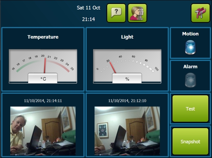
Example 10-foot interface for the controller application
Note
The first time that a client connects to the server, immediately after the server has been restarted, the server might seem slow in its response. Don't worry. Managed code is compiled the first time it is executed. So, the first time a client connects, a lot of code will be just in time (JIT) compiled. Once JIT compilation is done, the application will execute much quicker. Such a JIT-compiled code will stay compiled until the server application is closed or the server is restarted.