
There are numerous programming languages that we can use with EV3. Two of the most popular are LabVIEW and RobotC. This is due in large part because of the student robotics competitions such as For Inspiration and Recognition of Science and Technology (FIRST) robotics, where both LabVIEW and RobotC are approved languages. Both of these programming languages must be purchased but do allow a higher level of programming than the EV3 LEGO MINDSTORMS language, which is written by LEGO and National Instruments. The more serious EV3 enthusiasts will do their programming in leJOS (Java), MonoBrick (.NET languages—C#, VB, F#), or ev3dev (which allows you to use Python, C, C++, and numerous others). In this chapter, we will have a brief overview of LabVIEW and RobotC. We will cover the following topics:
- The LabVIEW language, which includes:
- Front Panel and Block Diagrams
- Programming blocks
- Robot tools
- SubVIS
- The RobotC language, which includes:
- Commands
- Remote control
- Graphical programming
LabVIEW is a higher-level programming language used widely in science and engineering. LabVIEW is made by National Instruments, who, with LEGO, created both EV3 and its immediate predecessor, NXT. The entire EV3 LEGO MINDSTORMS software is based on LabVIEW and is meant to be a kid-friendly version of the more advanced software. There are middle schools, which have LabVIEW integrated into their curriculum so that the learning curve is not that high. You can find copies of the student edition of LabVIEW for under $50, which is a bargain compared to the full professional edition that is over $1,000! For this chapter, I used the 2014 version of LabVIEW with the LEGO MINDSTORMS add-on modules. LabVIEW works fine on both Macs and PCs. The EV3 add-ons were released in the fall of 2014. At the time of writing this book, not all of the NXT features were fully updated for EV3.
When you first start a robot project in LabVIEW you use the Schematic Editor to assign the EV3 ports to your sensors and motors. In the following screenshot, you can see how I have assigned the motors to ports B and C, a Touch Sensor to port 1, an Ultrasonic Sensor to port 2, and a Color Sensor to port 3. On the left-hand side in the following screenshot, you can see controls to use the Schematic Editor to make individual motors move a certain amount. I have found this very useful in making sure that the mechanical aspects of my robot are solid without worrying about the programming.

You can also get feedback from the sensors. In the preceding screenshot, you can see how the values for the motor encoders are displayed. You can actually assign names to the motors, instead of calling them by the default names such as Large Motor 1. In the following screenshot, the Schematic Editor is focusing on the Ultrasonic Sensor. You can see a graph of the distance measurements coming back from the Ultrasonic Sensor.

The Schematic Editor is similar to the Port View in the EV3 MINDSTORMS software. In the upper right-hand corner, you may notice a pull-down menu that says Master. In Chapter 11, Communication Between Robots, we will discuss how to allow EV3 bricks to communicate in what is called a master-slave function. The Schematic Editor allows you to assign all of the sensors for each brick you have, which is not possible in the EV3 MINDSTORMS software.
Programs in LabVIEW are called Virtual Instruments (VIs). When I think back to my early days in electronics, I remember buying Heathkits. You would solder dozens of resistors, capacitors, and transistors onto circuit boards. You would then control your electronics project with potentiometers connected to knobs and dials on the outside of your black box. Today, the Heathkit has been replaced with Arduino and other Do It Yourself electronics kits. Mistakes can take a long time to fix. If you use the wrong resistor, it takes a while to desolder and reconnect a new component.
LabVIEW is used as a virtual electronics black box. In the Block Diagram, you wire together all of your electronic components. On the Front Panel, you have your dials, knobs, meters, and gauges.
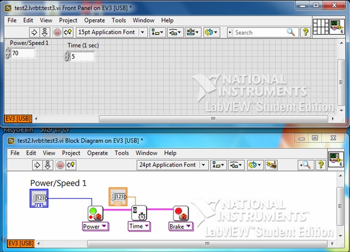
In the preceding screenshot, I have written a simple program in LabVIEW, which will move the robot forward for 5 seconds, and then stop. In the Block Diagram, which is on the bottom half of the screenshot, you can see three blocks. There is a Power block, a Wait for Time block, and a Brake block. These three blocks are wired together with a thick wire that dictates the flow of the program, quite similar to the EV3 LEGO MINDSTORMS software. Data wires connect two control blocks to the Power and Wait blocks. These control blocks accept values from the settings on the Front Panel, which are labeled Power/Speed 1 and Time.
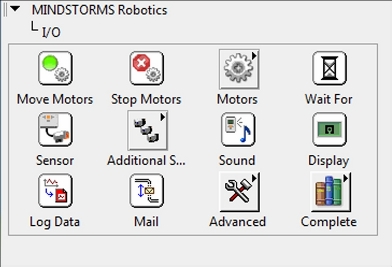
LabVIEW is a huge programming language with hundreds of programming blocks. The LEGO MINDSTORMS add-on module tries to simplify things by only presenting the most used blocks. In the following screenshot, you can see several I/O programming block categories. These blocks control the motors, sensors, and perform data logging, display, and Bluetooth functions. You can already see the similarities to the EV3 LEGO MINDSTORMS software.
The programming blocks used to manipulate data in your EV3 programs are quite extensive, as you can see in the following screenshot. Again, the total number of loops and data types in the menu has been trimmed to the most used programming blocks. An advanced user can certainly bring in other blocks.

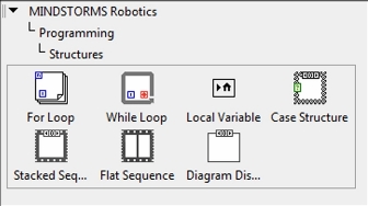
Delving deeper into the hierarchy of programming blocks, if we look at the Structures category in the following screenshot, we can see more than just the simple loop and switch blocks we have in the EV3 LEGO MINDSTORMS software.
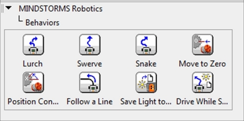
Learning to combine all of these programming blocks can be a bit daunting. To help you do this, LabVIEW has a menu of preprogramming VIs of some very common robot maneuvers, which they call Behaviors. Each block in the following screenshot is actually a full VI with several programming blocks inside of it. You can modify those blocks or use them directly in your own programs.
In the following screenshot is a small VI that will display motion sensor readings onto the EV3 brick display. We have a for loop, which will repeat for 10 iterations. The first programming block is a Read Ultrasonic block, which is measuring in centimeters and taking data from port 2. A flow wire and a data wire connect to the drawNumber block, which displays the distance measurement on the screen of EV3. The flow wire next leads into a Wait for Time block that waits for 1 second. The last block inside the loop is another drawNumber block. The input of this block is actually the index of the iteration of the loop. The constant 3 above the drawNumber block lowers this to the third line of text on the screen.

Although they look like simple programming blocks, in truth, all of the blocks in the preceding screenshot are actually VIs (or LabVIEW programs) of themselves.
We will now look in depth at one of the Behavior VIs we saw previously, the line following VI. You will notice that the line following VI uses several numeric functions. In the following screenshot, you may recognize that many of these numeric functions look like the traditional programming flow charts that you may have seen in an elementary computer programming class. Much of the logic behind LabVIEW is based on the flow chart concept.

The line following VI will use the Add, Subtract and Multiply functions from the preceding menu. When you look at the line following VI in the following screenshot, the first thing you will notice is the while loop. As opposed to the for loop that runs for a certain number of iterations, the while loop continued indefinitely as long as the Enter Button is not pushed on the brick. Instead of assigning a setpoint value to track along, the user needs to begin by placing the robot on the edge of the tracking line. As you can see mentioned in the comment field, before the loop begins, an initial measurement is made by the Read Color Sensor block. A data wire connects the value read from this initial measurement as the setpoint and finds the difference to color sensor readings, which are made inside of the while loop. This difference or error is multiplied by the gain, which in the following program is approximately 0.3 to produce a correction.
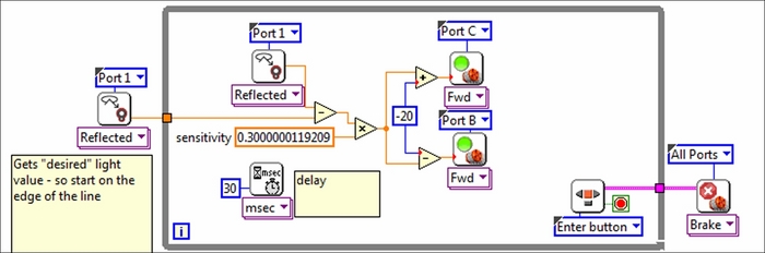
This correction is then either subtracted or added to the speed of the left and right wheels respectively. A delay of 30 milliseconds is added to the while loop so that doesn't run too fast. You will find that the LabVIEW code does run more efficiently than the EV3 language. After the while loop is broken, the robot comes to a halt.
Some nice features in the EV3 LEGO MINDSTORMS software are the Image Editor, the Sound Editor, and the Data Logger. Those editors in LabVIEW are even better. The Image Editor in LabVIEW allows you to upload a wider variety of image files. The Sound Editor likewise has more abilities. One built-in example is the following Piano Player tool, which you can see in the following screenshot:

As we saw in Chapter 9, Experiment Software and Data Logging, the Data Logger in the EV3 LEGO MINDSTORMS software had many great features. I was always frustrated that I could not graph one sensor value as a function of another sensor value on the same graph. Additionally, all you can really do with the data is make a graph. With LabVIEW, you can save the sensor data as a .dat file. This allows you to import the data at a later time to control your robot!
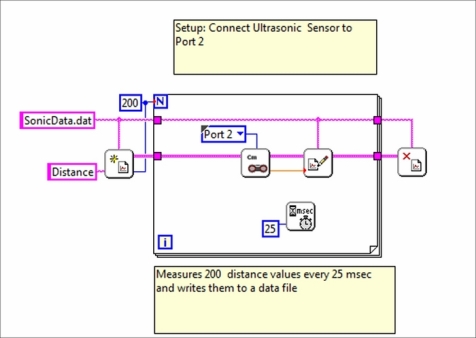
In the following screenshot, you can see a VI that takes a series of data from the Ultrasonic Sensor and writes it to a file. Another frustration is that in the EV3 LEGO MINDSTORMS software, you can only write one datum to a file. In the following screenshot, we see a for loop that runs for 200 iterations. The VI begins with a Start Data File block. This block creates a data file called SonicData.dat, and prepares it to accept distance values. The Read Ultrasonic block inside of the loop is connected by a flow wire and a data wire to the Add Data Point block. This block appends a single datum to the data file. The loop pauses 25 milliseconds between iterations. A third wire at the top sends a string with the name of the file. After the loop has terminated, the flow wires lead us to a Close Data File block.
Similar to the Data Logger in the EV3 LEGO MINDSTORMS software, we have a Data Viewer in LabVIEW that allows us to make a graph of our values, as you can see in the following screenshot:

If you wanted to, you could even place a copy of this graph on display on the Front Panel of your program.
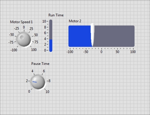
There is actually a wide variety of buttons, knobs, and sliders you can use to control the variables and constants in your VI. In the following screenshot, I have chosen a knob, two sliders, and a dial. For the current settings on the Front Panel, this VI will program the robot to move forward, pause, and then turn.
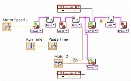
In the following screenshot, you can see the Block Diagram, which accompanies the previous Front Panel. The Block Diagram is actually a disorganized mess, which includes a broken or disconnected wire. One nice feature of LabVIEW is that with a few simple commands it will remove broken wires and clean up your Block Diagram.

The following screenshot is much easier to understand compared to the disorganized mess that you saw earlier. The VI begins with the Move Motor block, which is controlled by the knob on the Front Panel. The Wait for Time block is controlled by the slider on the Front Panel. After braking, the next Wait for Time block is controlled by a dial. Next, you can see that the flow of the program splits as each motor is controlled separately allowing a coordinated turn. The motor slider on the Front Panel sends its positive value to one motor, and a negative value to the other motor.
The concept of the My Block is based on the SubVI from LabVIEW. In the following screenshot, we can see a development of the program we used earlier in the Line following VI section. However, the program is quite large and difficult to view. Thus, we need to develop a hierarchy for the program by using a SubVI. We will make the entire right half of the following VI into a SubVI:

Now when we look at the program it is easy to follow. The robot moves forward at 75 percent power until it is within 40 centimeters of a barrier. It then stops for two seconds to prepare to track a line.

Just like My Block, if you click on the SubVI, it will open up and you can look deeper into the hierarchy, which is what I have done in the following screenshot:

You will find that LabVIEW is used widely throughout the fields of science and engineering. Learning LabVIEW is a valuable skill in stem fields. However, at professional robotics companies, most programming is done with line code.