
In this section, we will spend some time going through what a graph database model is. Specifically, we would like to clarify a common misunderstanding that originates from our habitual relational database system knowledge.
In a relational system, we have been taught to start out modeling with an Entity-Relationship diagram. Using these techniques, we can start from a problem/domain description (what we call a user story in today's agile development methodologies) and extract the meaningful entities and relationships. We will come back to this later, but essentially, we usually find that from such a domain description, we can:
- Extract the entities by looking at the nouns of the description
- Extract the properties by looking at the adjectives of the description
- Extract the relationship by looking at the operating verbs in the description
These are, of course, generic guidelines that will need to be tried and tested on every domain individually to make sure that it is an appropriate fit. However, for now, let's look at the following diagram:
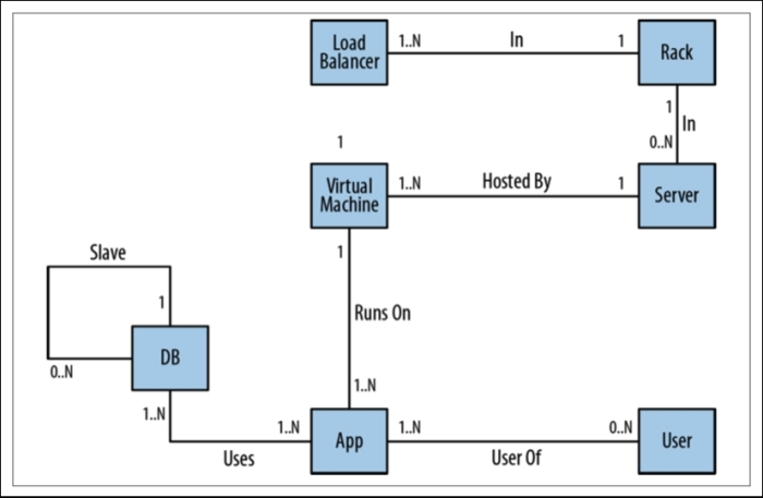
An Entity-Relationship diagram
As you can see from the preceding figure, ER diagrams have the advantage of at least attempting to capture the business domain in a real-world model. However, they suffer from quite a few disadvantages too. Despite being visually very similar to graph visualizations, ER diagrams immediately demonstrate the shortcomings of the relational model to capture a rich domain. Although they allow relationships to be named (something that graph databases fully embrace, but relational stores do not), ER diagrams allow only single, undirected, named but otherwise unqualified relationships between entities. In this respect, the relational model is a poor fit for real-world domains where relationships between entities are numerous, semantically rich, and diverse. The labeled property graph, as we have seen previously, allows for a much richer description of the domain, specifically with regard to the relationships between the entities—which will be multiple, directed, and qualified through properties.
The problem of relational ER modeling becomes even worse when we take the ER diagram to an actual system and are faced with serious limitations. Let's take a look at how one of the relational model's fundamental problems becomes apparent when we take the diagram to a test in a real-world implementation.
Let's take the model, which was described previously, to the database administrator for an actual implementation. What happens then is that in this implementation, the relational model inherently causes complexity. What you can see in the following diagram is that for every relationship where we can have n-n combinations, we actually need to introduce something that links the two tables together. This is what we call a join table, and this will be used by every query that requests a combination of the n-n entities.
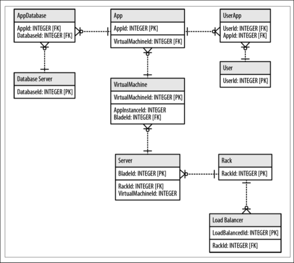
The database schema
In the previous example, we introduced the AppDatabase table to link applications to database servers and the UserApp table to link Users to Applications. These join tables are only necessary to deal with the shortcomings of the relational model, and they complicate our lives as database administrators and application developers. They introduce unwanted complexity.