
Chapter 7. Modeling Ordered Interactions: Sequence Diagrams
Use cases allow your model to describe what your system must be able to do; classes allow your model to describe the different types of parts that make up your system’s structure. There’s one large piece that’s missing from this jigsaw; with use cases and classes alone, you can’t yet model how your system is actually going to its job. This is where interaction diagrams , and specifically sequence diagrams, come into play.
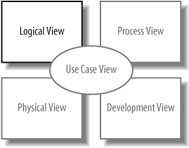
Sequence diagrams are an important member of the group known as interaction diagrams. Interaction diagrams model important runtime interactions between the parts that make up your system and form part of the logical view of your model, shown in Figure 7-1.
Sequence diagrams are not alone in this group; they work alongside communication diagrams (see Chapter 8) and timing diagrams (see Chapter 9) to help you accurately model how the parts that make up your system interact.
Tip
Sequence diagrams are the most popular of the three interaction diagram types. This could be because they show the right sorts of information or simply because they tend to make sense to people new to UML.
Sequence diagrams are all about capturing the order of interactions between parts of your system. Using a sequence diagram, you can describe which interactions will be triggered when a particular use case is executed and in what order those interactions will occur. Sequence diagrams show plenty of other information about an interaction, but their forté is the simple and effective way in which they communicate the order of events within an interaction.
Participants in a Sequence Diagram
A sequence diagram is made up of a collection of participants—the parts of your system that interact with each other during the sequence. Where a participant is placed on a sequence diagram is important. Regardless of where a participant is placed vertically, participants are always arranged horizontally with no two participants overlapping each other, as shown in Figure 7-2.
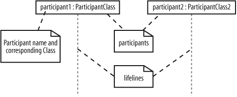
Each participant has a corresponding lifeline running down the page. A participant’s lifeline simply states that the part exists at that point in the sequence and is only really interesting when a part is created and/or deleted during a sequence (see "Participant Creation and Destruction Messages" later in this chapter).
Participant Names
Participants on a sequence diagram can be named in number of different ways, picking elements from the standard format:
name[selector] :class_name ref decomposition
The elements of the format that you pick to use for a particular participant will depend on the information known about a participant at a given time, as explained in Table 7-1.
|
Example participant name |
Description |
|
admin |
A part is named |
|
: ContentManagementSystem |
The class of the participant is |
|
admin : Administrator |
There is a part that has a name of |
|
eventHandlers [2] : EventHandler |
There is a part that is accessed within an array at element 2, and it is of the class |
|
: ContentManagementSystem ref cmsInteraction |
The participant is of the class |
The format used when creating names for your participants is totally up to you—or maybe your company’s style guide. In this book, we lowercase the first word in the participant name to make sure that there is as little confusion as possible with the name of a class. However, this is just our convention—similar to the conventions used when naming objects and classes in Java—and is not something specified by UML.
Time
A sequence diagram describes the order in which the interactions take place, so time is an important factor. How time relates to a sequence diagram is shown in Figure 7-3.

Time on a sequence diagram starts at the top of the page, just beneath the topmost participant heading, and then progresses down the page. The order that interactions are placed down the page on a sequence diagram indicates the order in which those interactions will take place in time.
Time on a sequence diagram is all about ordering, not duration. Although the time at which an interaction occurs is indicated on a sequence diagram by where it is placed vertically on the diagram, how much of the vertical space the interaction takes up has nothing to do with the duration of time that the interaction will take. Sequence diagrams are first about the ordering of the interactions between participants; more detailed timing information is better shown on timing diagrams (see Chapter 9).
Events, Signals, and Messages
The smallest part of an interaction is an event. An event is any point in an interaction where something occurs, as shown on Figure 7-4.
Events are the building blocks for signals and messages. Signals and messages are really different names for the same concept: a signal is the terminology often used by system designers, while software designers often prefer messages.
In terms of sequence diagrams, signals and messages act and look the same, so we’ll stick to using the term “messages” in this book.
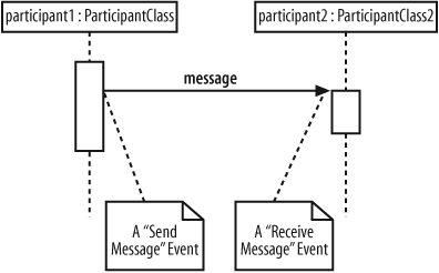
An interaction in a sequence diagram occurs when one participant decides to send a message to another participant, as shown in Figure 7-5.
Messages on a sequence diagram are specified using an arrow from the participant that wants to pass the message, the Message Caller, to the participant that is to receive the message, the Message Receiver. Messages can flow in whatever direction makes sense for the required interaction—from left to right, right to left, or even back to the Message Caller itself. Think of a message as an event that is passed from a Message Caller to get the Message Receiver to do something.
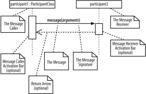
Message Signatures
A message arrow comes with a description, or signature. The format for a message signature is:
attribute = signal_or_message_name (arguments) : return_typeYou can specify any number of different arguments on a message, each separated using a comma. The format of an argument is:
<name>:<class>The elements of the format that you use for a particular message will depend on the information known about a particular message at any given time, as explained in Table 7-2.
|
Example message signature |
Description |
|
doSomething( ) |
The message’s name is |
|
doSomething(number1 : Number, number2 : Number) |
The message’s name is |
|
doSomething( ) : ReturnClass |
The message’s name is |
|
myVar = doSomething( ) : ReturnClass |
The message’s name is |
Activation Bars
When a message is passed to a participant it triggers, or invokes, the receiving participant into doing something; at this point, the receiving participant is said to be active. To show that a participant is active, i.e., doing something, you can use an activation bar, as shown in Figure 7-6.

An activation bar can be shown on the sending and receiving ends of a message. It indicates that the sending participant is busy while it sends the message and the receiving participant is busy after the message has been received
Nested Messages
When a message from one participant results in one or more messages being sent by the receiving participant, those resulting messages are said to be nested within the triggering message, as shown in Figure 7-7.
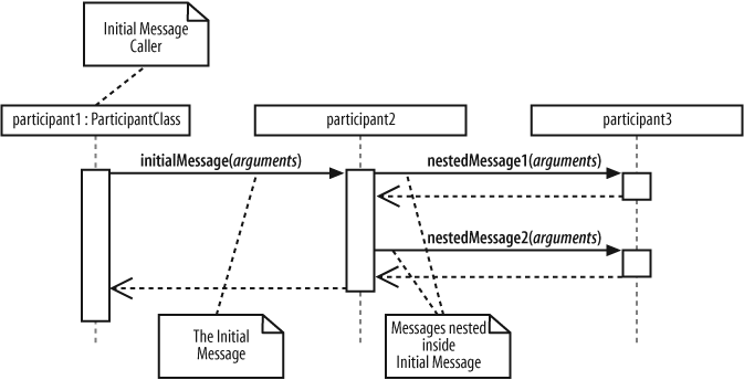
In Figure 7-7, participant1 sends initialMessage(..) to participant2. When participant2 receives initialMessage(..), participant2 becomes active and sends two nested messages to participant3. You can have any number of nested messages inside a triggering message and any number of levels of nested messages on a sequence diagram.
Message Arrows
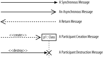
The type of arrowhead that is on a message is also important when understanding what type of message is being passed. For example, the Message Caller may want to wait for a message to return before carrying on with its work—a synchronous message. Or it may wish to just send the message to the Message Receiver without waiting for any return as a form of “fire and forget” message—an asynchronous message.
Sequence diagrams need to show these different types of message using various message arrows , as shown in Figure 7-8.
To explain how the different types of messages work, let’s look at some simple examples where the participants are actually software objects implemented in Java.
Synchronous Messages
As mentioned before, a synchronous message is invoked when the Message Caller waits for the Message Receiver to return from the message invocation, as shown in Figure 7-9.
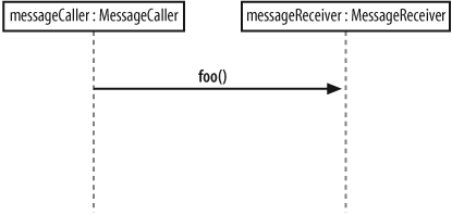
The interaction shown in Figure 7-9 is implemented in Java using nothing more than a simple method invocation, as shown in Example 7-1.
public class MessageReceiver
{
   public void foo(  )
   {
      // Do something inside foo.
   }
}

public class MessageCaller
{
   private MessageReceiver messageReceiver;

   // Other Methods and Attributes of the class are declared here

   // The messageRecevier attribute is initialized elsewhere in
   // the class.

   public doSomething(String[] args)
   {
      // The MessageCaller invokes the foo(  ) method

      this.messageReceiver.foo(  ); // then waits for the method to return

      // before carrying on here with the rest of its work
   }
}
Asynchronous Messages
It would be great if all the interactions in your system happened one after the other in a nice simple order. Each participant would pass a message to another participant and then calmly wait for the message to return before carrying on. Unfortunately, that’s not how most systems work. Interactions can happen at the same point in time, and sometimes you will want to initiate a collection of interactions all at the same time and not wait for them to return at all.
For example, say you are designing a piece of software with a user interface that supports the editing and printing of a set of documents. Your application offers a button for the user to print a document. Printing could take some time, so you want to show that after the print button is pressed and the document is printing, the user can go ahead and work with other things in the application. The regular synchronous message arrow is not sufficient to show these types of interactions. You need a new type of message arrow: the asynchronous message arrow.
An asynchronous message is invoked by a Message Caller on a Message Receiver, but the Message Caller does not wait for the message invocation to return before carrying on with the rest of the interaction’s steps. This means that the Message Caller will invoke a message on the Message Receiver and the Message Caller will be busy invoking further messages before the original message returns, as shown in Figure 7-10.
A common way of implementing asynchronous messaging in Java is to use threads, as shown in Example 7-2.

If you’re not too familiar with how threads work in Java, check out Java in a Nutshell , Fifth Edition (O’Reilly) or Java Threads (O’Reilly). See "Applying Asynchronous Messages" later in this chapter for a practical example of asynchronous messages.
public class MessageReceiver implements Runable {

   public void operation1(  ) {
      // Receive the message and trigger off the thread

      Thread fooWorker = new Thread(this);
      fooWorker.start(); // This call starts a new thread, calling the run(  )
                      // method below

      // As soon as the thread has been started, the call to foo(  ) returns.

   }

   public void run(  ) {
      // This is where the work for the foo(  ) message invocation will
      // be executed.
   }
}

public class MessageCaller
{
   private MessageReceiver messageReceiver;

   // Other Methods and Attributes of the class are declared here

   // The messageRecevier attribute is initialized elsewhere in
   // the class.

   public void doSomething(String[] args) {
      // The MessageCaller invokes the operation1(  ) operation

      this.messageReceiver.operation1(  );

      // then immediately carries on with the rest of its work
   }
}
The Return Message
The return message is an optional piece of notation that you can use at the end of an activation bar to show that the control flow of the activation returns to the participant that passed the original message. In code, a return arrow is similar to reaching the end of a method or explicitly calling a return statement.
You don’t have to use return messages —sometimes they can really make your sequence diagram too busy and confusing. You don’t have to clutter up your sequence diagrams with a return arrow for every activation bar since there is an implied return arrow on any activation bars that are invoked using a synchronous message.
Tip
Although a message will often be passed between two different participants, it is totally normal for a participant to pass a message to itself. Messages from an object to itself are a good way of splitting up a large activation into smaller and more manageable pieces and, in terms of software, can be thought of as being very similar to making a method call to the this reference in Java and C#.
Participant Creation and Destruction Messages
Participants do not necessarily live for the entire duration of a sequence diagram’s interaction. Participants can be created and destroyed according to the messages that are being passed, as shown in Figure 7-11.

To show that a participant is created, you can either simply pass a create(..) message to the participant’s lifeline or use the dropped participant box notation where it is absolutely clear that the participant does not exist before the create call is invoked. Participant deletion is shown by the ending of the participant’s lifeline with the deletion cross.
Software participant creation in Java and C# is implemented using the new keyword, as shown in Example 7-3.
public class MessageReceiver {
   // Attributes and Methods of the MessageReceiver class
}

public class MessageCaller {

   // Other Methods and Attributes of the class are declared here

   public void doSomething(  ) {
      // The MessageReceiver object is created
      MessageReceiver messageReceiver = new MessageReceiver(  );
   }
}
With some implementation languages, such as Java, you will not have an explicit destroy method
, so it doesn’t make sense to show one on your sequence diagrams. Example 7-3 is one such case where the messageReceiver object will be flagged for destruction when the doSomething( ) method completes its execution. However, no additional messages have to be passed to the messageReceiver to make it destroy itself since this is all handled implicitly by the Java garbage collector.
In these cases, where another factor such as the garbage collector is involved, you can either leave the object as alive but unused or imply that it is no longer needed by using the destruction cross without an associated destroy method, as shown in Figure 7-12.

Bringing a Use Case to Life with a Sequence Diagram
It’s time to take a closer look at a sequence. Specifically, let’s look at a sequence diagram that is going to model the interactions that need to occur to make the Create a new Regular Blog Account use case happen.
Figure 7-13 should look familiar; it is just a quick reminder of what the Create a new Regular Blog Account use case looks like (see Chapter 2).
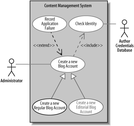
Briefly, the Create a new Regular Blog Account use case is a special case of the Create a new Blog Account use case. It also includes all of the steps provided by the Check Identity use case and may optionally execute the steps provided by the Record Application Failure use case, if the application for a new account is denied. Figure 7-13 is a pretty busy use case diagram, so feel free to jump back to Chapter 2 to remind yourself of what is going on.
A Top-Level Sequence Diagram
Before you can specify what types of interaction are going to occur when a use case executes, you need a more detailed description of what the use case does. If you’ve already completed a use case description, you already have a good reference for this detailed information.
Table 7-3 shows the steps that occur in the Create a new Regular Blog Account use case according to its detailed description.
|
Main Flow |
Step |
Action |
|
|
1 |
The Administrator asks the system to create a new blog account. |
|
|
2 |
The Administrator selects the regular blog account type. |
|
|
3 |
The Administrator enters the author’s details. |
|
|
4 |
The author’s details are checked using the Author Credentials Database. |
|
|
5 |
The new regular blog account is created. |
|
|
6 |
A summary of the new blog account’s details are emailed to the author. |
Table 7-3 actually shows all of the steps involved in the Create a new Regular Blog Account use case, including any steps that it has inherited from Create a new Blog Account or reused from Check Identity. This has been done just so you can easily see all of the Main Flow steps in one place.
In practice, you would probably just look up all three use case descriptions separately without actually going to the bother of actually merging them.
Table 7-3 only shows the Main Flow—that is the steps that would occur without worrying about any extensions—but this is a good enough starting point for creating a top-level sequence diagram, as shown in Figure 7-14.
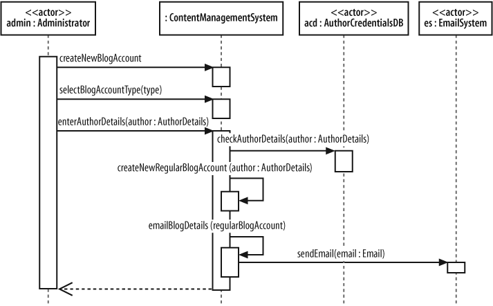
Tip
Figure 7-14 focuses on the participants and messages that are involved in the use case. The same use case was modeled in Chapter 3 as an activity diagram, which focused on the processes involved rather than the participants.
Breaking an Interaction into Separate Participants
At this point, Figure 7-14 shows only the interactions that must happen between the external actors and your system because that is the level at which the use case description’s steps were written. On the sequence diagram, your system is represented as a single participant, the ContentManagementSystem; however, unless you intend on implementing your content management system as a single monolithic piece of code (generally not a good idea!), it’s time to break apart ContentManagementSystem to expose the pieces that go inside, as shown in Figure 7-15.

Sequence diagrams can get much more complicated by simply adding a couple of extra participants and some more detailed interactions. In Figure 7-15, the original sequence diagram has been refined so that the single ContentManagementSystem participant has been removed and in its place, more detail has been added showing the actual participants that will be involved.
Work on sequence diagrams invariably goes on throughout the life of your system’s model, and even getting the right participants and interactions in a detailed sequence diagram at the beginning can be hard work. Keeping your sequence diagrams up to date is also a challenge (see "Managing Complex Interactions with Sequence Fragments" later in this chapter); therefore, expect to spend some time working with your sequence diagrams until you get things right.
Applying Participant Creation
Something critical is missing from the sequence diagram shown in Figure 7-15. The title of the use case in which the sequence diagram is operating is Create a new Regular Blog Account, but where is the actual creation of the blog account? Figure 7-16 adds the missing pieces to the model to show the actual creation of a regular blog account.
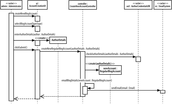
Participant lifelines are particularly useful when showing that a participant has been created. In Figure 7-16, the AuthorDetails and RegularBlogAccount participants are not in existence when the sequence diagram begins but they are created during its execution.
The AuthorDetails and newAccount:RegularBlogAccount participants are created by corresponding create messages. Each create message
connects directly into the title box for the participant being created, passing any information needed when creating the new participant. By dropping the participant’s title box to the point where the create message is actually invoked, the diagram can clearly show the point where the participant’s lifeline begins.
Applying Participant Deletion
Let’s say that the authorDetails:AuthorDetails participant is no longer required once the newAccount:RegularBlogAccount has been created. To show that the authorDetails:AuthorDetails participant is discarded at this point, you can use an explicit destroy message connected to the destruction cross, as shown in Figure 7-17.
Applying Asynchronous Messages
So far, all of the messages on our example sequence diagram have been synchronous; they are executed one after the other in order, and nothing happens concurrently. However, there is at least one message in the example sequence that is a great candidate for being an asynchronous message, as shown in Figure 7-18.

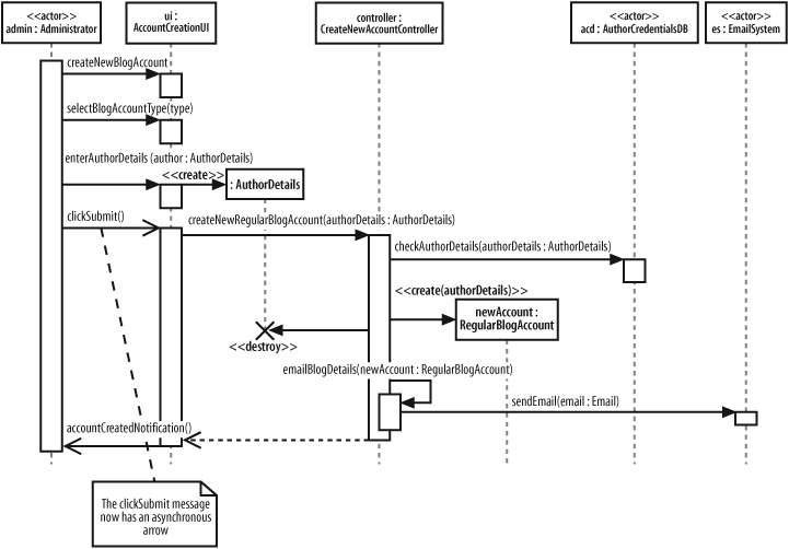
In Figure 7-18, when the Administrator clicks on the submit button the system freezes, until the new blog account has been created. It would be useful to show that the user interface allows the Administrator to carry on with other tasks while the content management system creates the new account. What we need is for the clickSubmit( ) message to be asynchronous.
Converting the clickSubmit( ) from a synchronous to an asynchronous message means that the sequence diagram now shows that when the new regular blog account information is submitted, the user interface will not lock and wait for the new account to be created. Instead, the user interface allows the Administrator actor to continue working with the system.
For the Administrator to receive feedback as to whether the new blog account has been created, the simple return arrow has to be replaced with a new accountCreationNotification( ) asynchronous message since asynchronous messages do not have return values.
Managing Complex Interactions with Sequence Fragments
Most of what you’ve seen in this chapter will have been pretty familiar to anyone who has used sequence diagrams in UML 1.x. But now it’s time for something completely different.
In the bad old days of pre-UML 2.0, sequence diagrams quickly became huge and messy, and contained far too much detail to be easily understood or maintained. There were no built-in, standard ways to show loops and alternative flows, so you had to “grow your own” solutions. This tended to contribute to the size and complexity of the sequence diagrams rather than helping to manage it.
Something new was needed to help the modeler work with the detail that a sequence diagram needed to capture, allowing her to create organized and structured sequence diagrams that showed complex interactions such as loops and alternate flows. The answer from the UML 2.0 designers was the sequence fragment.
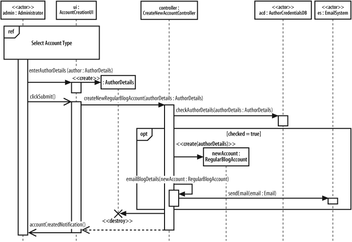
A sequence fragment is represented as a box that encloses a portion of the interactions within a sequence diagram, as shown in Figure 7-19.
A sequence fragment’s box overlaps the region of the sequence diagram where the fragment’s interactions take place. A fragment box can contain any number of interactions and, for large complex interactions, further nested fragments as well. The top left corner of the fragment box contains an operator. The fragment operator indicates which type of fragment this is.

In Figure 7-19, the operator is opt, which means that this is an optional fragment. All the interactions contained within the fragment box will be executed according to the result of the fragments guard condition parameter.
Some fragment types do not need additional parameters as part of their specification, such as the ref fragment type discussed in the next section, but the guard condition parameter is needed by the opt fragment type to make a decision as to whether it should execute its interactions or not. In the case of the opt fragment type, the interactions that the fragment contains will be executed only if the associated guard condition logic evaluates to true.
Using a Sequence Fragment: The ref Fragment
The ref type of sequence fragment finally alleviates some of the maintenance nightmare presented by the huge sequence diagrams that are often created for complex systems. In Figure 7-20, the ref fragment represents a piece of a larger sequence diagram.
The interactions by which the Administrator actor selects a blog account type for creation are now contained within the referenced sequence fragment. Figure 7-21 shows how the referenced fragment can be expressed on a separate sequence diagram.

Along with managing the sheer size of large sequence diagrams, the ref fragment also presents an opportunity to reuse a set of common interactions. Several ref fragment boxes can reference the same set of interactions, thereby reusing the interactions in multiple places.
Tip
The ref fragment type works in a very similar manner to the <<include>> use case relationship. See Chapter 2 for more about the <<include>> use case relationship.
A Brief Overview of UML 2.0’s Fragment Types
UML 2.0 contains a broad set of different fragment types that you can apply to your sequence diagrams to make them more expressive, as shown in Table 7-4.
Sequence fragments make it easier to create and maintain accurate sequence diagrams. However, it’s worth remembering that no fragment is an island; you can mix and match any number of fragments to accurately model the interactions on a sequence diagram. Be wary if your diagrams become huge and unwieldy even when you are using fragments, since you might simply be trying to model too much in one sequence.
We’ve given you a brief overview of sequence diagram fragments here. All the different sequence diagram fragment types are a big subject in their own right and are a little beyond the scope of this book. For a more in-depth look at the different types of sequence diagram fragments, see UML 2.0 in a Nutshell (O’Reilly).
What’s Next?
Sequence diagrams are closely related to communication diagrams. So closely, in fact, that many modelers often don’t know when to use sequence versus communication diagrams. Chapter 8 describes communication diagrams and concludes with a comparison between the two, providing some tips about when to use which diagram type.
Sequence and communication diagrams are both interaction diagrams; timing diagrams are yet another type of interaction diagram. Timing diagrams specialize at showing time constraints involved with interactions, which is especially useful for real-time systems. Timing diagrams are covered in Chapter 9.
If your sequence diagram is getting cluttered with too many messages, step back and look at interaction diagrams on a higher level with interaction overview diagrams. Interaction overview diagrams model the big picture perspective on interactions that occur within your system. Interaction overview diagrams are described in Chapter 10.