In Chapter 15, I introduced you to the COMPARE block, which takes two numbers, A and B, and examines them to determine if A is greater than, less than, or equal to B (depending on the option you select). The result of this comparison is then converted to a Logic data type (either True or False) that can be used as output using a data wire. In Chapter 16, I showed you how the RANGE block examines a value and determines whether it falls between an upper and lower value—a True or False response is then generated.
In this chapter, I'm going to show you a block that is similar to the COMPARE and RANGE blocks, but not quite the same. Instead of comparing two numbers, this block will compare two Logic data type inputs and also output a True/False Logic data type response.
The Logic block is an interesting one (shown in Figure 17-1).

Let me set up a scenario for SPOT that I think will help you understand how this block works. I've attached a Light sensor and a Sound sensor to SPOT. Here's my first bit of pseudo-code for SPOT to try out.
Me: SPOT, I want you to move forward three rotations if two conditions are True.
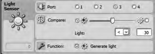
Me: The first condition is that the Light sensor detects a light level below 30.
Me: The second condition is that the Sound sensor detects a sound level below 20.
What will happen here? Well, SPOT will check to see if his Light sensor detects a low light level in the room (<30). He'll also check to see if his Sound sensor is detecting a quiet room (<20). Recall from the discussion of sensors that a sensor can return a True or False reply based on the conditions you have configured the sensor to detect.
Let's start your program by dropping a Light sensor block on the beam and configuring it, as shown in the configuration panel in Figure 17-2.
Next, you'll add a Sound sensor block and configure it as shown in Figure 17-3.

Now you have two sensors that will check the conditions of the light and sound in the room.
If you look back at your pseudo-code, SPOT will move forward only if both of the sensors are triggered. This means the Light sensor must receive a value less than 30 for the room's lighting level, and the Sound sensor must receive a value less than 20 for the room's sound level—both conditions must exist or SPOT will not move forward.
What will happen if the room is bright and quiet? SPOT will not move.
What will happen if the room is dark and loud? SPOT will still not move.
What happens if the room is bright and loud? SPOT will get a headache. Just kidding—he still won't move.
As you can tell, he's only going to move if the room is both quiet and dark.
So, how can SPOT quickly examine the lighting and sound conditions of the room and decide if he can move forward or not? Simple—he'll use the COMPARE block.
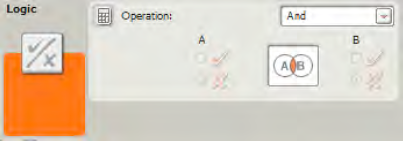
Go ahead and drop the LOGIC block on the beam, as shown in Figure 17-4.

Take a look at the drop-down menu in the Operation section. The drop-down menu has four options: And, Or, Xor, and Not. For now, select the And option (I'll explain the other three options shortly).
Next, I want you to drag a wire out of the Yes/No data plug on the Light sensor block and connect it to the A input data plug on the LOGIC block, as shown in Figure 17-5.
Drag another wire out of the Yes/No data plug on the Sound sensor block and connect it to the B input data plug on the LOGIC lock, as shown in Figure 17-6.


Now, let me explain what is happening so far. The LOGIC block is taking a Yes/No response from the Light sensor. It is also taking a Yes/No response from the Sound sensor. By selecting the And option on the LOGIC block, you are forcing the LOGIC block to take the result in plug A (Yes or No) and the result in plug B (Yes or No) and add them together to create a single Yes/No response. I can already hear you asking, "How do you add Yes/No responses?"
Well, the answer is fairly simple and relies on the option you selected in that drop-down menu (the And, Or, Xor, and Not options):
And option: If you select the And option, both responses must be Yes for a final Yes result to be generated. If plug A is Yes and plug B is No, then the final result will be No. Likewise, if plug A is No and plug B is Yes, the final result will still be No. And if plug A is No and Plug B is No, the final result is No. Only when both inputs are Yes will a Yes result be generated.
Or option: If you select the Or option, only one response must be Yes for a final Yes result to be generated. If plug A is Yes and plug B is No, then the final result will be Yes. Likewise, if plug A is No and plug B is Yes, the final result will still be Yes. If both plug A and plug B are both Yes, then the final result will be Yes. Only if plug A is No and Plug B is No, the final result is No.
Xor option: This is a weird one. If you select the Xor option, only one plug value can be Yes for a final Yes result to be generated. If plug A is Yes and plug B is No, then the final result will be Yes. Likewise, if plug A is No and plug B is Yes, the final result will still be Yes. However, if plug A and plug B are both Yes, the final result will be No. And if plug A and plug B are both No, the final result is No. Remember, for a Yes output response, only one of the logic input values can be Yes...only one.
Not option: This is another strange one. This option doesn't really return a final value—it simply changes the Logic value input for plug A to its opposite. For example, if plug A is Yes, then the output for plug A will be No. This option reverses the Logic value for you and nothing else. Be aware that plug B is disabled for the Not option.
Now, let's finish up your sample program. If you look back at Figure 17-6, you now have the LOGIC block ready to provide a Yes/No response (using a data wire).
If you recall, you are testing to see if the Sound sensor detects a value below 30 and the Light sensor detects a value below 20. If these conditions are both true, then SPOT will be allowed to move forward three rotations. If either of these two conditions is not true, SPOT will not be allowed to move.
So, your next step is to drop in a SWITCH block to test the condition of the LOGIC block. First, select Value from the Control section drop-down menu. Next, choose Logic from the Type section drop-down menu. You can leave the Flat View box checked, because you only have two possible options (True or False). This configuration is shown in Figure 17-7.
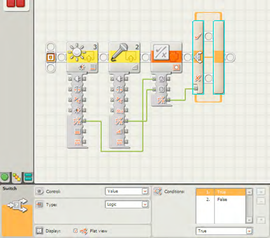
Now, here's where it can get a little tricky. If the Light sensor detects a light value below 30, then it sends a True value to the LOGIC block. If the Sound sensor detects a sound value below 20, then it sends a True value to the LOGIC block. You have configured the LOGIC block using the And option, because you want to test if both conditions are True. If they are, the LOGIC block will send a True (or Yes) value to the SWITCH block. If either of the conditions is False, the LOGIC block will send a False value to the SWITCH block.
All that's left is to drop in a MOVE block for the True condition in the SWITCH block, as shown in Figure 17-8.

If the SWITCH block detects a True response from the LOGIC block, the MOVE block executes (three forward rotations), and the program ends. If the SWITCH block detects a False response from the LOGIC block, there are no additional blocks to run, and the program ends without SPOT moving. All that's needed is to add a NXT BUTTON WAIT block at the end of the program that will allow the MOVE block to finish and wait for the user to push a button to end the program.
Think you've got the hang of the LOGIC block? Then take a look at Excerise 17-1. If you get stumped, I've placed one possible solution to the exercise at the end of the chapter.
Place a series of blue and red circles on the floor in a long straight line. Have SPOT roll forward and follow the line of circles. When SPOT is over a red circle, yell out "STOP!" Create a program that will only stop SPOT's movement when both the color red is detected and the Sound sensor detects a noise over a level of 75.
The LOGIC block is a useful tool for you to take two Logic data type responses (Yes/No or True/False) and "add" them together to produce one Logic data type. Are you wondering what you would do if, for example, you had four Logic data type inputs and needed to combine them? You would need to use two LOGIC blocks: each block would take two of the Logic data type input values and provide a final Logic response. You can see this in Figure 17-9. These two Logic responses would then be combined using a third LOGIC block to obtain the true "final" Logic response. Confusing? A little. But when you start using the LOGIC block, you'll begin to see how it can be used with LOOP and SWITCH blocks to give your robots even better decision-making abilities.

Figures 17-10 through 17-14 show the complete program and configuration panels for Exercise 17-1. The MOVE block will continue to spin the motors indefinitely until the Loop is broken and the program ends.