
At this point in the book, we're almost finished with the blocks in the Common Palette. Throughout the remainder of the book, I'll be introducing you to blocks and concepts that will allow you to build more complex programs that do more than simply tell your bots to move forward, backward, or in a circle.
Now, I'd like to take a short break to introduce you to another concept. I'll make this one fun too, I promise. Then, I'll show you a new NXT-G programming block that you'll really like.
Let's go back to our friendly bot, SPOT. Once again, let's just pretend that he's got a pair of ears and can understand verbal commands. I'm going to give him a set of unusual commands:
Me: SPOT, I want you to move forward six rotations, stop, and turn right 90 degrees.
[SPOT moves forward six rotations, stops, and turns right.]
Me: SPOT, move forward six rotations, stop, and turn right 90 degrees.
[SPOT moves forward six rotations, stops, and turns right.]
Me: SPOT, move forward six rotations, stop, and turn right 90 degrees.
[SPOT moves forward six rotations, stops, and turns right.]
Me: SPOT, move forward six rotations, stop, and turn right 90 degrees.
[SPOT moves forward six rotations, stops, and turns right.]
Now, where is SPOT? That's right—he's back where he started. The path he followed was square-shaped, and he's once again waiting for my instructions.
If you were to create an NXT-G program for SPOT to make this square, you'd simply place eight MOVE blocks on the workspace (as shown in Figure 11-1) and configure each MOVE block with the same two settings, right? One MOVE block will spin motors B and C for six rotations and the next MOVE block will have SPOT make a right turn. I then repeat this pattern three more times, for a total of eight MOVE blocks.

Well, it would work. But it seems like a lot of work just to make SPOT drive around in a square and return to his starting position. Is there a better way?
Let's see if we can improve the pseudo-code a bit:
Me: SPOT, I want you to move forward six rotations, stop, and turn right 90 degrees.
[SPOT moves forward six rotations, stops, and turns right.]
Me: SPOT, I want you to repeat my first set of instructions three more times.
[SPOT moves forward six rotations, stops, and turns right.]
[SPOT moves forward six rotations, stops, and turns right.]
[SPOT moves forward six rotations, stops, and turns right.]
Much better! I only had to tell him the instructions one time and ask him to do them again three more times. It takes just as long for SPOT to perform the movements, but I get to save my voice a bit!
In the pseudo-code, I gave SPOT commands, and I set a condition. You should be able to find the commands for SPOT: move, stop, turn right 90 degrees. But what is a condition? Remember, a condition is simply a rule your robot (SPOT) must follow and meet before the program can continue or end. So my rule for SPOT is "Repeat my first set of instructions three more times." I could have told him to repeat it twice or 60 times; it doesn't matter as long as SPOT knows the rule and follows it.
Instead of telling him to repeat it three times, could I have used a different condition? Sure—here are some examples:
Me: SPOT, I want you to repeat my first set of instructions until your Touch sensor is triggered.
Me: SPOT, I want you to repeat my first set of instructions until your internal timer goes over 45 seconds.
Me: SPOT, I want you to repeat my first set of instructions forever.
Another way to look at it is that I've given SPOT instructions to do over and over and over—until something else happens. It could be that the Touch sensor is pressed or the Color sensor detects a green line on the ground or the time reaches infinity (but trust me, SPOT's batteries won't last that long; eventually he'll stop)!
If SPOT keeps doing something over and over again, someone might say, "That robot is loopy!" And that's exactly right—he's looping. He is executing a loop!
What is a loop? In real life, a loop could be a racetrack or a long piece of string with its ends tied together—no matter how large it is, if you follow its path, you'll eventually come back to your starting position. A programming loop is very similar. It just circles back on itself, either forever or until you program an escape from the loop.
And it just so happens that the NXT-G software has a block just for this special occasion—the LOOP block (see Figure 11-2).

The LOOP block, by itself, is very boring. By default, it is set to loop forever; you can see this in the Control section of the LOOP block's configuration panel.
Right now, any blocks that I drop inside the LOOP block will keep repeating, over and over. Let me give you an example.
Note
When dropping a block inside a LOOP block, continue to hold down the mouse button and move the new block inside the LOOP block until the LOOP block expands.
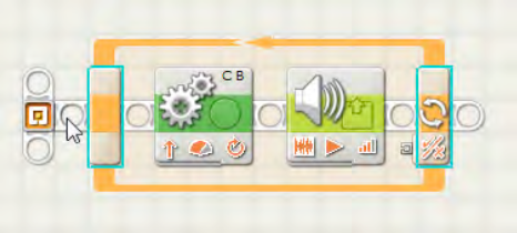
I'm going to place a MOVE block inside the LOOP block. This MOVE block will be configured to spin the motors in Ports B and C for one rotation (see Figure 11-3).
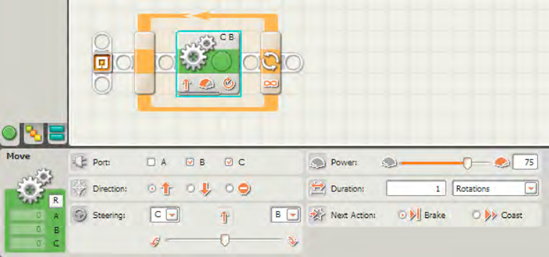
I then save the program, upload it to SPOT, and run it. SPOT moves forward one rotation, and then there's a slight pause. Next, SPOT moves forward one more rotation, and there's another pause. This continues until I get tired of watching him, and I cancel the program.
The pause is occurring when the MOVE block finishes its action and the LOOP block checks its condition (this happens very quickly). Remember, the condition is a rule that the bot must follow. The rule for this program is for the LOOP to continue forever, so it runs again and again and again—you get the picture. That explains the short pause between rotations of SPOT's motors. SPOT is checking to see if it can end the loop; because it is set to run forever, the program jumps back to the start of the LOOP block and runs the MOVE block again.
Now let's change the condition. How would we tell SPOT to run the MOVE block four times?
Take a look at the LOOP block's configuration panel. The Control section has a drop-down menu. Go ahead and click it, and you'll see some options (shown in Figure 11-4).

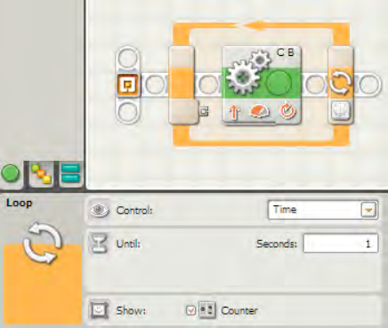
The options are Forever, Sensor, Time, Count, and Logic. Let me start with one of the easiest of the bunch: Time. Select Time from the drop-down menu in the Control section, and the configuration panel will change (see Figure 11-5).

When you select Time as the Control, you have access to another section. The Until section is where you'll enter a time (in seconds) in the text box. This is the amount of time that any programming blocks inside the LOOP block will run. Earlier I mentioned that a loop will cycle forever until you program an escape. Well, by setting this time limit, you've provided that escape from the loop. And that escape goes by another term—loop break.
A loop break occurs when the loop stops. After the loop breaks, your program will continue with the next programming block, or it will stop if the LOOP block is the last block in your program. Easy, isn't it? The loop can break if you cancel the program, but it can also be configured to break when a specific condition is met. In one of my earlier examples, I told SPOT to stop when the Touch sensor was bumped. The Touch sensor will break the LOOP block.
I need to make one important point: if there are multiple blocks inside the LOOP block, they will all complete before the LOOP block breaks. So if you configure your LOOP block to run for 25 seconds and the blocks inside take 40 seconds to finish one run, the 25-second time limit will expire before the internal blocks are finished, so the LOOP block will not loop again.
What happens if the blocks inside take 15 seconds to run? Well, when the LOOP block starts, the timer begins counting down from 25. After the blocks inside have completed their first run, there are still ten seconds left on the timer. So the program jumps back to the start of the LOOP block and runs the inner blocks again. But this time, the timer will run down to zero before the blocks have completed. When the blocks have finished executing, the LOOP block checks the timer, sees that time has expired, and breaks the loop.
The other section, Show, has one option: you can either enable or disable the counter. Every time the LOOP block loops, the counter increases by one. If the box is checked, the LOOP block will provide a small data plug (see Figure 11-6). I covered data hubs and data plugs in Chapter 7, but what you need to know about this option is that you can use the data plug to provide an output Number data type. This Number value is the number of loops the LOOP block has performed. This value could be useful for more advanced programs where you wish to keep track of the number of times a LOOP block loops and use this for decision-making. For example, you might consider creating a program that uses the number value provided by the counter to increase the distance that the Ultrasonic sensor scans. Inside the loop, you could wire the counter plug to the Ultrasonic sensor's Trigger Point input data plug. Every time the loop executes, the Ultrasonic sensor will increase the distance it scans (in inches or centimeters) by a value of one.
Let' take a look at another easy Control option for the LOOP block—the Forever setting shown in Figure 11-7.
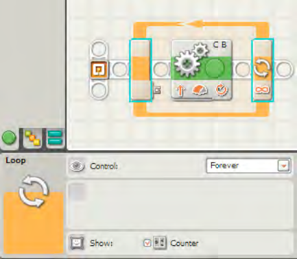
When you configure a LOOP block to run forever, that's exactly what will happen: any blocks inside the loop will run over and over again until you cancel the program or the batteries give out.
Now click the drop-down menu in the Control section, and select Sensor; next, click the drop-down menu in the Sensor section to see the drop-down menu shown in Figure 11-8.
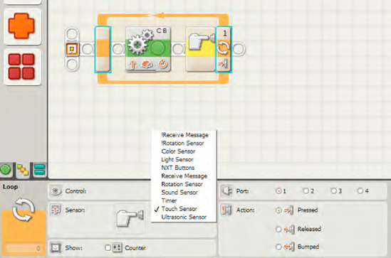
As you can see, the Sensor section's drop-down menu offers, many options, including Light Sensor, NXT Buttons, Receive Message, Rotation Sensor, Sound Sensor, Timer, Touch Sensor, Color Sensor, and Ultrasonic Sensor. Most of these were covered in Chapter 9 and are easy to use. What you are doing when you select one of these options is configuring the trigger that will break the loop.
For example, in Figure 11-9, I have selected the NXT Buttons options from the Sensor section drop-down menu.
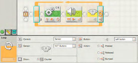
In this example, I have configured the loop to break when the Left button on the NXT Brick is pressed. Inside the loop, I have configured one MOVE block to move SPOT forward one rotation. I have also added a SOUND block that will play a short beep. Once the program is running, SPOT will move forward one rotation and beep, and he'll continue to do this until the Left button is pressed. (I'll have to chase him to press the Left button!)
Note
In some situations, the break condition must occur at the exact moment that the LOOP block is checking its break condition. For example, in Figure 11-9, if I'm walking with my robot and press the Left button during the MOVE block's execution or the SOUND block's execution, the loop will not break. I must press the Left button after the robot beeps but before it begins moving again. There are ways to fix this and I'll show you how later in this chapter.
Just keep in mind that when you choose an option from the Sensor section, you are configuring a condition that must be met before the LOOP block will break.
Your next possible option is to break the loop with a Count. Select Count from the drop-down menu in the Control section (see Figure 11-10).

When using the Count option, you must provide an integer value in the Until section's text box. You cannot use negative numbers, only zero and positive integers (1, 2, 3, and so on).
In Figure 11-10, I've configured the LOOP block to break when the Count reaches 12. When I run the program, SPOT will execute the first MOVE and SOUND blocks. When these are finished, Count goes from 0 to 1, and the loop starts again. The MOVE and SOUND blocks are executed again, and Count increases to 2. After the blocks have been executed a total of 12 times (Count = 12), the loop will break, and the program will end.
The last option available to break a loop is the Logic setting, shown in Figure 11-11.
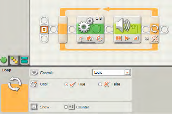
In Figure 11-11, notice that when Logic is selected in the Control section drop-down menu, a small data plug appears on the LOOP block.
This data plug will accept only a Logic data wire as input. This means that the LOOP block will break when the Logic data type (True or False) you selected in the Until section is received. I'll show you an example using this option in the next section.
That's it for configuring an individual LOOP block. But there's one more thing I'd like to show you with the LOOP block: nested loops.
To demonstrate this new concept, I'm going to create a simple program for SPOT that I'd like you to follow and create yourself. First, let me explain what I want SPOT to do using pseudo-code:
Me: SPOT, I want you to move forward along a circular path for 3.5 rotations and then use your speaker to beep! Do this two more times (for a total of three times), and then check to see if your Light sensor detects a Light level greater than 90. If the Light sensor is not triggered, repeat this entire process.
I can use a LOOP block to hold a MOVE block and a SOUND block that will repeat three times. This is shown in Figure 11-12.

I've dropped a MOVE block and a SOUND block inside this LOOP block. In the Control section, you'll see that I've selected the Count option and set it to 3. The next thing I want to do is see if the Light sensor is triggered. I've added and configured the Light sensor in Figure 11-13.

But now I've got a problem. If you follow along with the program, you can see that the LOOP block will run three times: the MOVE and SOUND blocks inside it will execute three times and then the LOOP breaks. Then the Light sensor is tested. If the Light level is greater than 90, the program ends. But what if the Light level is less than 90? How do I make the program run again? One option is to simply have SPOT run the program again. I'll have to press the Enter button on the Brick to run the program again, but this will work. It will also be very annoying. There ought to be an easier way, and there is.
Take a look at Figure 11-14, and you'll notice that the entire program I just created is now inside another LOOP block.
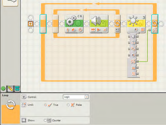
This is called a nested loop, which just means a loop inside a loop. When the program runs, any blocks inside the outer LOOP block will run—this includes the inner LOOP block! First, the inner LOOP block will run three times (executing the MOVE and SOUND blocks inside it) and then break. Then the Light sensor will send a True/False Logic response to the outer LOOP block's data plug. If the Light sensor does not detect a light level greater than 90, the outer LOOP block will not break and will run whatever is inside it again.
Notice in Figure 11-14 that there is a data wire connecting the Light sensor to the outer LOOP block. In the Control section of the outer LOOP block, I've selected the Logic option and programmed it to wait until it receives a True response from the Light sensor block. If the Light sensor block does not detect a light level greater than 90, the Yes/No data plug sends a False signal to the outer LOOP block, causing the outer LOOP block to loop again.
For my final example, Figure 11-15 shows a complicated situation. Can you determine what will happen?
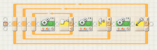
Yes, that is a loop inside a loop inside a loop—three LOOP blocks! If you examine this program carefully, you should be able to see what will happen when it is run.
First, the innermost LOOP block will begin to execute a MOVE block until the Touch sensor is triggered (in this case, bumped). Then the innermost LOOP block will break. Next, the middle LOOP block will begin executing a MOVE block until the Ultrasonic sensor is triggered. At that point, the middle LOOP block will break. Then the final, outer LOOP block will begin executing a MOVE block until the Sound sensor is triggered. Finally, when the Sound sensor is triggered, the outer LOOP block breaks, and the program ends.
The LOOP block is a very useful and powerful block; you should spend some time experimenting with all the different options. You'll use the LOOP block often when you want your robots to repeat certain blocks.
Now, I have a slightly more complicated exercise for you to examine. Earlier in the chapter I mentioned a situation where I would have to press the Left button at the exact moment when the last NXT-G block executes inside a block—otherwise the LOOP block wouldn't detect the button push and it would begin running the program again. How might we fix this?
Take a close look at Figure 11-16. It may look a little strange to you with that extra block sitting way up above the main program. Can you see how the program works? I'm using a block that might be new to you—the VARIABLE block. I'll cover it in more detail in Chapter 14, but for now just follow along and configure the block as I describe here. After examining the program, modify it to break the loop when the Color sensor detects a red line on the floor.

I created this program by adding an extra sequence beam. To do this, move your mouse pointer to the very start of the sequence beam, as shown in Figure 11-17.
While holding the Shift key down, click and hold your left mouse button and drag up to where the first bend in the new beam will appear. This is shown in Figure 11-18.
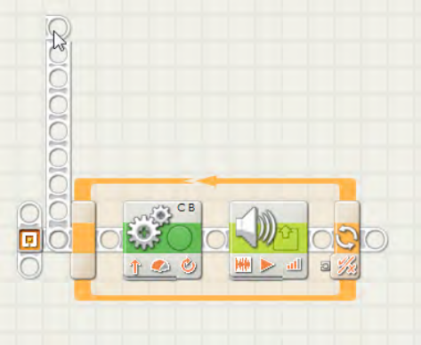
Next, release the mouse button and drag the pointer to the right. Drag it to increase the length of the new beam that will run parallel to the main beam below it. Double-click your left mouse button to create the ending of the new beam. This is shown in Figure 11-19.

Now, drop a NXT BUTTONS WAIT block onto the new beam, as shown in Figure 11-20. (Dropping additional blocks will automatically extend the new beam to the right.)

Any blocks added to your new beam will run in parallel to the blocks on the main beam. Next, add a VARIABLE block to the top beam and configure it as shown in Figure 11-21.

Notice that the configuration panel for the VARIABLE block has its Action setting set to Write and the Value is set to True. Also, the Logic 1 value is selected in the List box.
Finally, add another VARIABLE block inside the LOOP block. Drag a wire from its Yes/No data plug, as shown in Figure 11-22, and configure it as shown in the configuration panel.
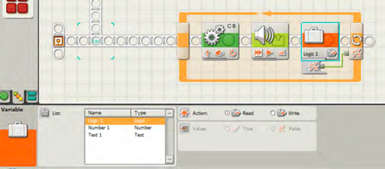
Figure 11-22. Add another VARIABLE block inside the loop and configure it to Read the Logic 1 value.
Now, when the program runs, all the blocks inside the LOOP block will execute until the VARIABLE block sends a True signal and breaks the loop. How will the VARIABLE block get a True signal? On the top beam, after the left button is pressed, the VARIABLE block after it will write a True value to the variable named Logic 1. By default, the VARIABLE block starts out holding a False value. When the left button is pressed, the Logic 1 value changes from False to True... and then when the LOOP block finishes the SOUND block, the Logic 1 value is checked in the VARIABLE block and the True value it now holds will break the loop!
Now you know how to have your robot repeat certain actions such as turning left and moving forward ten rotations. Up next in Chapter 12, I'm going to show you how to give your robots the ability to make choices: should SPOT turn left and move forward five rotations or turn right and move forward two rotations?
Figures 11-23 and 11-24 show the complete program and the configuration panel settings for the LOOP and COLOR SENSOR WAIT and VARIABLE blocks (you can use any settings you like for the MOVE and SOUND blocks). Notice that once again I'm using a LOOP block configured to break when it detects a logical True value stored in the VARIABLE block placed inside the loop. For the Color sensor configuration panel, I've configured it to look for the color red by dragging the left and right drag bars to surround the color red and setting the Compare setting to Inside Range. If you want to read about the VARIABLE block, feel free to skip to Chapter 14 and come back to this exercise when you're done.


