
Have you ever had someone perform a card trick and ask you to pick a card from the deck? There are 52 cards in a standard deck (the two jokers don't count), and if it's been properly shuffled, you should be able to pick a random card from the deck.
It's the same with rolling a pair of dice. Each die has the potential to roll a number from one to six. When you roll a normal pair of dice, the numbers that appear are random. The odds of rolling a two on one die are the same as rolling a six; they all have the same likelihood of appearing. What allows this to occur is simple randomness.
Your robots also have the ability to generate random numbers. You might want to build a robot that can roll a virtual set of dice or maybe pick a number between 1 and 1,000. Read on to learn how to have your robots generate random numbers and display them on the LCD screen.
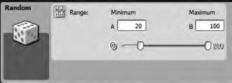
Your robots can use the RANDOM block to generate numbers in a range (a minimum value and maximum value) that you define. Data wires can also be used to provide the minimum and maximum values that will be generated. The RANDOM block is found on the Complete Palette in the Data fly-out menu. Take a look at the block and its configuration panel in Figure 14-1.

The RANDOM block is another one of those blocks that is very simple to use. There are not a lot of options to configure, but what is there is important.
The first thing I want you to notice in the configuration panel is the Minimum and Maximum number fields in the Range section. In these boxes, you can type in the upper and lower values for the numbers you want the RANDOM block to generate. For NXT-G version 1.0, the minimum value can never be less than zero, and the maximum value can never be greater than 32,767. For NXT-G version 2.0, the minimum value can be negative.
There is one other method you can use for defining the minimum and maximum values. There are two small tabs on the slider bar below the minimum and maximum values. You can drag the leftmost small tab to set the minimum value. The rightmost small tab can be dragged to set the maximum value.
Note
One thing you should be aware of is that the slider bar can be used only for defining a range between 0 and 100. If you wish to use a maximum value greater than 100, you need to type the number into the maximum number field. If you are using version 2.0, you must also type in a negative value for the minimum number field; the slider bar is not capable of setting values less than zero.
Now, let's do an example with SPOT using pseudo-code:
Me: SPOT, show a random number on your LCD screen between 20 and 80 until I press the left button.
To do this, I'll first drop a RANDOM block on the beam (see Figure 14-1). I've told SPOT that I want the minimum value to be no less than 20, so I'll use the slider bar to set the minimum value (see Figure 14-2).
Now, what if I had wanted the value to be between 20 and 80 but not include 20? Remember, the minimum and maximum values you define will be included in the possible numbers generated by the RANDOM block. So if I didn't want 20 to be a possible number, I would simply drag the slider bar again to set the minimum value to 21. By doing this, 21 would be a possibility, but 20 would be no longer allowed.
My final step is to set the maximum value; I drag the slider bar to set the maximum value to 80 (see Figure 14-3).

Now all that's left to do is to have SPOT display the value on the LCD screen. To do this, I need to introduce you to another NXT-G programming block: NUMBER TO TEXT.
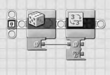
The NUMBER TO TEXT block is also found on the Complete Palette in the Data fly-out menu. I'll drag and drop it after the RANDOM block, so you can see its configuration panel (shown in Figure 14-4).

Why do I need to use the NUMBER TO TEXT block? Remember, the DISPLAY block is capable only of displaying an image, text, or a drawing, Since it cannot display a number value, we have to convert a number into text. The text "1" is not the same as the number value "1"—the text "1" is treated just like any other character in the alphabet.
The NUMBER TO TEXT block requires the number it will send to the LCD screen to come into its single-input data plug or be typed into the Number field on the configuration panel. The number is then converted to text that can be displayed using the DISPLAY block. So, let me go ahead and drag a wire from the output Number data plug on the RANDOM block into the input Number data plug on the NUMBER TO TEXT block. You can see this in Figure 14-5.
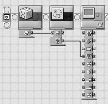
As you can tell from Figure 14-5, the text you want to display will come from the output data plug on the NUMBER TO TEXT block. I'll drop in a DISPLAY block and drag another wire from the output Text data plug on the NUMBER TO TEXT block into the input Text data plug on the DISPLAY block (see Figure 14-6). Remember to set the DISPLAY block to display text, not images or drawings, in its configuration panel.
One mistake often made is to drag a wire out of the RANDOM block's plug and drag it into the DISPLAY block's last data plug, the one that has the # symbol and looks like it should take a number. That data plug controls the radius of a circle (if a circle is drawn on the LCD screen), so all you'd be doing is using the RANDOM block to control the radius of a circle instead of displaying the value on the screen. The only way to display the number generated by the RANDOM block is to use the NUMBER TO TEXT block.
Instead of using a TIME WAIT block to keep the text on screen as I've done with past examples, I'm going to use an NXT BUTTON WAIT block this time. The RANDOM number generated will stay on the LCD screen until I press the Left button.
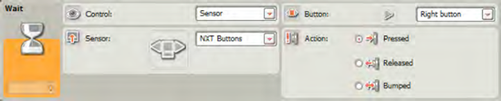
To do this, I drop in an NXT BUTTON WAIT block and configure it as shown in Figure 14-7.

I've used a WAIT block with the Control section set to Sensor. In the Sensor section, I selected NXT Buttons from the drop-down menu. For the Button section, select Left button from the drop-down menu, and finally, in the Action section, I selected Pressed. By configuring the WAIT block this way, the random number will stay on the LCD screen until I press the left button on the NXT Brick. Then the program ends.
Not too difficult, huh?
One final thing I want to point out on the NUMBER TO TEXT block is the output Number data plug. This block will still allow you to keep and use the random number you generated in a Number format. You might need that random number later in the program. If so, you can drag a data wire out of the output Number data plug—it will still be a number and not changed to text.
So now you know how the RANDOM block is configured and used. If you want your robot to move randomly around the room, for example, you could configure a RANDOM block to generate a number between one and four. Program your bot to go left if the number is one, right if the number is two, forward if the number is three, and in reverse if the number is four. By using a random number to control the bot's direction, you can give the bot some unpredictable behavior. Refer to Chapter 12's discussion of the SWITCH block for using conditions such as a random number to control movement.
Now let's see if you've got a grasp of how the RANDOM block works. Read over Exercise 14-1 and create a new program for SPOT. If you get stuck, I've provided one possible solution at the end of the chapter.
Create a program that will have your robot move forward (from its START position) a random number of degrees (and stopping at its END position). You are then going to have the robot reverse direction and move backwards a random value so that it ends up somewhere between the START position and the END position. Have your robot display the number of degrees it has moved forward (to the END position) and also display the number of rotations it rolls backwards. Keep both these values displayed on the screen. When the movement has completed, use a WAIT block to allow you time to view the values on the LCD screen before the program ends.
Next, in Chapter 15, we'll look at the COMPARE block. The COMPARE block uses two types of data—number and logic. It compares two number values and then provides a logical data type—True or False—depending on how you've configured the two number values to be compared. Confusing? It'll all be cleared up in the next chapter.
Figures 14-8 through 14-16 provide you with the complete program and the configuration panels for Exercise 14-1.

In Figure 14-8, I've configured the RANDOM block to select a value between 90 and 180. So the maximum distance the robot's wheels will travel is 180 degrees and the minimum is 90 degrees.
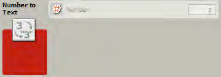
Figure 14-9 is grayed out because I'm using a data wire to carry a number value into the block.
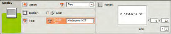
Figure 14-10 shows that I've selected Text as the Action for the DISPLAY block. For this first DISPLAY block, I've also left the Display setting checked (to clear the LCD screen).
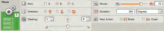
Figure 14-11 shows that the robot has been configured to roll forwards using Degrees.

Figure 14-12 shows the second RANDOM block. This time, I've configured it to select a value between 10 and 80. This will ensure that when the robot rolls backwards it ends up somewhere between its START and END positions.

Another NUMBER TO TEXT block is shown in Figure 14-3. This will pass the second random number generated to the next DISPLAY block.

Notice in Figure 14-14 that I've unchecked the Display setting and changed the Line to display the second value to Line 6. This will ensure that the original random number and the new random number are both displayed on the LCD screen.

Another MOVE block is used to roll the robot backwards a random number of degrees, shown in Figure 14-15.
Finally, when the robot has completed its movement, both random numbers will be displayed on the screen until the user (you) presses the right button, as configured in Figure 14-16.