
6. Disk Partitions and Filesystems
Cylinders, sectors, tracks, and heads are the building blocks of spindle storage. Understanding the millions of bytes confined to a space that is half an inch thick, two inches wide, and three inches in length is critical to data recovery.
Consider the smallest form of storage that every person, at one time or another, has held in the palm of his or her hand. Most of us over the age of 25 recollect ravaging our desk, digging for the all-important, “critical-to-life” 1.44 MB floppy. This critical piece of plastic never fails to be found under the heaviest object on the desk. It is amazing that any data survives on the floppy after removing the seven-pound differential equations bible that was covering it. However, today’s storage needs require much larger devices and more advanced methods to protect and recover the data they hold.
The following key topics are discussed in this chapter:
• SCSI and IDE data storage concepts
• The Ext2/3 filesystem
• The concepts of Cylinder, Head, and Sector (CHS)
• Global unique identification
• Partition tables
Throughout the chapter, we present scenarios that deliver real-world examples of the topic discussed in each section.
Background
Let’s examine the following key filesystems and disk partitions concepts before getting into details: Intelligent/Integrated Drive Electronics (IDE), SCSI, and bit functions. Simply saying that data resides on a platter in the form of magnetic polarization of the surface greatly oversimplifies the nature of the beast.
IDE and SCSI
IDE is perhaps the most common drive type used by Linux, although it is slowly losing ground to SCSI in the Linux market because of the increasing popularity of large storage arrays. SCSI has not been around much longer than IDE; it was renamed around 1981/1982 from Shugart Associates System Interface (SASI) to Small Computer Systems Interface (SCSI). The IBM Mainframe 360 had the capability to speak to several devices simultaneously on any given I/O bus as early as 1960, so it could be said that SCSI started then. No matter the case, with more and more companies using storage consolidation, SCSI disk arrays are truly becoming commonplace.
Bit Calculation
Another key concept is bit calculation. Regardless of SCSI, IDE, or other storage medium you choose, you should always start with the basics: the calculation of bits and bytes. The best way to depict the combinations is through a chart, as shown in Table 6-1.
Table 6-1. Bit and Byte Calculations
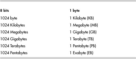
Eight bits written as 00000000 or 0000 0000 defines an eight-bit address with 256 possible combinations, as listed in Table 6-2.
Each bit has a value of either “0” for off or “1” for on, instructing a virtual gate/door to allow 5 volts DC (power-conservative machines and newer technologies use 3.2 volts DC) to pass. Given that a bit only has two states (on or off) rather simplifies the importance of a single entity.
The following is a list of key terms and their definitions to help you understand the data on a platter discussed later in this chapter.
• sBit—Single binary element defined as on or off (1 or 0, respectively).
• Nibble—Four bits.
• Byte—Two nibbles, eight bits, or a character.
• Word—Sixteen bits, or two bytes. # on most hardware implementations.
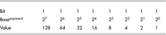
Other terms, such as “binary,” “octal hex/decimal,” and “ASCI,” are just other ways to represent the same value under different systems. Table 6-3 lists binary value “bits” converted to decimal and hexadecimal values.
Table 6-3. Converted Binary Values

Each bit has a mathematical value defined as 2X, whereby we define the base value of every bit equal to numeric value 2 multiplied by an exponent X. The combined value of the eight bits depends on the order in which they are interpreted, “left to right” or “right to left.”
The values of bits are calculated utilizing the Endian order, which is the direction the bits are read. Binary data is written and calculated by the majority of humans in most significant bit (MSB), LEFT, to least significant bit (LSB), RIGHT, order. Starting right to left, the bit values have exponential values beginning with zero and incrementing to seven. Although the exponent values change, the base value always remains at two. Note that the hardware platform determines the default bit order, which is referred to as “Little Endian or Big Endian.” The following shows the MSB and LSB difference through od and bvi:
"od -h /dev/disk_device_file | head"
"dd if=/dev/disk_device of=/tmp/disk_device.out bs=512 count=1" utilize
"bvi /tmp/disk_device.out".
...
"0001 0e83 143f 003f 0000 4d46 0000 0000" By od -h
"0100 830E 3F14 3F00 0000 464D 0000 8000" By bvi
...
When reviewing binary data in Hex, we use the nibbles to perform calculations at great speed. Each nibble has a decimal value of 0 to 15 or Hex 0 to F.
The following is an example of a binary value being converted into a Hex value:
1010 1001 = A9
This conversion is a two-step process. First, we need to address the left nibble. Break down the left nibble,“MSB,” by doing the following:
23 22 21 20
on, off, on, off
8, 0, 2, 0, = decimal 10, or Hex A
Then do the same for the right nibble, “LSB,” to achieve a value of 9 in Hex, as listed in Table 6-3.
Partition Table/Master Boot Record: Location
This section explores how to locate the Master Boot Record (MBR) and partition table for any disk.
We start with the location of the MBR on a standard Linux core drive. Core drive implies the root, or primary drive, that the operating system resides on in this example. cfdisk, fdisk with expert mode, dd, and many other tools enable us to collect the partition data. For an IDE or SCSI drive, just type cfdisk -P rst /dev/device_file where r equals RAW, s equals SECTORS, and t equals TABLE. This tool provides a look at a clean drive, as shown in the following example:
[root@localhost root]# cfdisk -P rst /dev/hde
Disk Drive: /dev/hde
Sector 0:
0x000: 00 00 00 00 00 00 00 00 00 00 00 00 00 00 00 00
0x010: 00 00 00 00 00 00 00 00 00 00 00 00 00 00 00 00
0x020: 00 00 00 00 00 00 00 00 00 00 00 00 00 00 00 00
0x030: 00 00 00 00 00 00 00 00 00 00 00 00 00 00 00 00
0x040: 00 00 00 00 00 00 00 00 00 00 00 00 00 00 00 00
0x050: 00 00 00 00 00 00 00 00 00 00 00 00 00 00 00 00
0x060: 00 00 00 00 00 00 00 00 00 00 00 00 00 00 00 00
0x070: 00 00 00 00 00 00 00 00 00 00 00 00 00 00 00 00
0x080: 00 00 00 00 00 00 00 00 00 00 00 00 00 00 00 00
0x090: 00 00 00 00 00 00 00 00 00 00 00 00 00 00 00 00
0x0A0: 00 00 00 00 00 00 00 00 00 00 00 00 00 00 00 00
0x0B0: 00 00 00 00 00 00 00 00 00 00 00 00 00 00 00 00
0x0C0: 00 00 00 00 00 00 00 00 00 00 00 00 00 00 00 00
0x0D0: 00 00 00 00 00 00 00 00 00 00 00 00 00 00 00 00
0x0E0: 00 00 00 00 00 00 00 00 00 00 00 00 00 00 00 00
0x0F0: 00 00 00 00 00 00 00 00 00 00 00 00 00 00 00 00
0x100: 00 00 00 00 00 00 00 00 00 00 00 00 00 00 00 00
0x110: 00 00 00 00 00 00 00 00 00 00 00 00 00 00 00 00
0x120: 00 00 00 00 00 00 00 00 00 00 00 00 00 00 00 00
0x130: 00 00 00 00 00 00 00 00 00 00 00 00 00 00 00 00
0x140: 00 00 00 00 00 00 00 00 00 00 00 00 00 00 00 00
0x150: 00 00 00 00 00 00 00 00 00 00 00 00 00 00 00 00
0x160: 00 00 00 00 00 00 00 00 00 00 00 00 00 00 00 00
0x170: 00 00 00 00 00 00 00 00 00 00 00 00 00 00 00 00
0x180: 00 00 00 00 00 00 00 00 00 00 00 00 00 00 00 00
0x190: 00 00 00 00 00 00 00 00 00 00 00 00 00 00 00 00
0x1A0: 00 00 00 00 00 00 00 00 00 00 00 00 00 00 00 00
0x1B0: 00 00 00 00 00 00 00 00 00 00 00 00 00 00 00 00
0x1C0: 00 00 00 00 00 00 00 00 00 00 00 00 00 00 00 00
0x1D0: 00 00 00 00 00 00 00 00 00 00 00 00 00 00 00 00
0x1E0: 00 00 00 00 00 00 00 00 00 00 00 00 00 00 00 00
0x1F0: 00 00 00 00 00 00 00 00 00 00 00 00 00 00 55 AA
Partition Table for /dev/hde
First Last
# Type Sector Sector Offset Length Filesystem Type (ID)
Flags
-- ------- -------- --------- ------ --------- ------------------ -------
Pri/Log 0 12594959 0#12594960 Free Space
None (00)
Partition Table for /dev/hde
---Starting--- ----Ending---- Start Number of
# Flags Head Sect Cyl ID Head Sect Cyl Sector Sectors
-- ----- ---- ---- ---- ---- ---- ---- ---- -------- ---------
1 0x00 0 0 0 0x00 0 0 0 0 0
2 0x00 0 0 0 0x00 0 0 0 0 0
3 0x00 0 0 0 0x00 0 0 0 0 0
4 0x00 0 0 0 0x00 0 0 0 0 0
Determining the start and end addresses of the partition table on the last example is rather easy because the drive is totally zeroed out. Bytes 1FE and 1FF with value “55 AA” are defined as the signature bytes (also known as the magic cookie) or standard word. These values define the end of the partition table and MBR. In this example, we cannot determine the exact starting point of the partition table without first determining the location of the signature bytes and counting backward.
The MBR contains two critical pieces of information: bootloader and partition table. Byte 01BE defines the start point of a partition table, though byte 0 defines the starting point of the MBR. In both cases, everything ends at byte 1FF.
In addition, cfdisk, fdisk, or any other tool will fail to control the drive without the signature word, as described previously with the value of “55 AA.” When new disks are discovered, cfdisk or fdisk requests a label if the magic cookie is null. After the magic cookie is established, any of the previous tools will enable a user to define partitions of any type. Note that raw data access does not follow this restriction and is not part of this chapter.
Partition Table/Master Boot Record: CHS Addressing
After the partition table has been identified, the user can proceed with Cylinder, Head, Sector (CHS) partition layout. The CHS model was the first defining structure that was developed for partitions, but due to size limits, it was replaced by Logical Block Addressing (LBA), which controls almost all disk partitions today. We begin with CHS to build a foundation for absolute addressing (CHS), thus limiting the total size, and then we discuss relative addressing (LBA).
With CHS, the start, end, and total sectors are defined within the constraints of a 6-bit sector, 10-bit cylinder, and 8-bit head, thus limiting this model to a max capacity of 8.4GB. In the following sections, examples and scenarios are included to help illustrate this concept.
Defining a Primary Partition
Pick your favorite tool and define a 100MB primary partition with type Linux, flagged as a bootable partition on a newly added disk starting at sector 0.
When complete, view your work by using dd if=/dev/disk_device_file of=/tmp/disk_device_file.out bs=512 count=1 where disk_device_file is equal to /dev/sdX or /dev/hdX depending on IDE or SCSI devices. Then, after using bvi, the partition info under the MBR should look similar to the following:
"bvi /tmp/disk_device_file.out"
**** 0 1 2 3 4 5 6 7 8 9 0A 0B 0C 0D 0E 0F
0x1B0: 00 00 00 00 00 00 00 00 00 00 00 00 00 00 80 01
0x1C0: 01 00 83 0E 3F 14 3F 00 00 00 46 4D 00 00 00 00
0x1D0: 00 00 00 00 00 00 00 00 00 00 00 00 00 00 00 00
0x1E0: 00 00 00 00 00 00 00 00 00 00 00 00 00 00 00 00
0x1F0: 00 00 00 00 00 00 00 00 00 00 00 00 00 00 55 AA
Note that the bold row beginning with **** does not actually exist; however, it is included here for illustrative purposes to identify the column.
Ending in “55 AA,” focus on byte 1BE with value 80, which is a boot flag mark. With byte 1BE set to 80, the BIOS loads the bootloader into memory. In the previous example, byte location 1BF–1C1 equals “01 01, 00,” which defines the CHS for the starting address space. Later, we discuss how to calculate C:H:S, but for now, these bytes are read (C)ylinders (H)eads (S)ectors, and these values are common on almost all first partition bootable drives.
Note
CHS does not align on the byte boundary; CHS is covered in more detail later in this chapter.
Byte 1C2 defines the partition type. In this example, byte 1C2 has value 83, which implies Linux native. Some of the possible values for byte 1C2 are:
4 FAT16 <32M 3c PartitionMagic 82 Linux swap c6 DRDOS/sec (FAT-
5 Extended 40 Venix 80286 83 Linux c7
A complete list can be found using fdisk, but beware that some of these values are not common and sometimes have multiple meanings. For example, what if byte 1C2 from sector 0 had a value of 42? By only considering the partition types defined by fdisk or cfdisk, we would most likely conclude that the partition type holds a secure filesystem (SFS). However, it’s much more probable that the partition is a Windows dynamic disk.
Note
For the remainder of this chapter, we denote Hex with value(H), Binary with value(B), Octal with value(O), and Decimal with value(D).
Byte 01C3 has value “0E,” which defines the ending head value in the current partition. 0E (H) = 14(D) heads exist in partition 1.
Bytes 01C4 and 01C5 have a value of “3F 14,” which defines the last sector and cylinder count for the partition. Because we are playing with a partition smaller than 8.4GB, we use absolute addressing for the CHS count. This changes when a partition is over 8.4GB to LBA, which we discuss later.
Using absolute addressing, only 6 bits are needed to define the last sector, and 10 bits are required to define the last cylinder, both of which are difficult to depict. Taking the values from locations 01C4 and 01C5 from the previous example and using Table 6-3, we can depict the sector and cylinder counts as follows:
Sector Cylinder
0011 1111 0001 0100
"3" "F" "1" "4"
Again, note that the sector only needs 6 bits, and 10 bits are required for the cylinder count. To meet this requirement, the bit order must be reestablished. Move the highvalue bits from the first byte and extend the high-value bits on the last byte.
0011 11{11 0001 0100} <---Placing brackets around 6 and 10 bits.
The following shows the move:
1111 11 {00 0001 0100}
3 F {0 1 4}
The cylinder count leaves us with 014(H) = 20 cylinders.
The sector count leaves us with 3F(H) = 63 sectors.
(Cylinder) × (Heads) × (Sectors) = (21) × (15) × (63) = 19845 sectors. However, do not forget about the offset. Offset is determined by byte 01C6–01C9.
Bytes 01C6–01C9 have the value “3F 00 00 00.”
Offset value 3F(H) = 63(D) sectors. The total size of our partition is 19845–63 = 19782 sectors.
To demonstrate the same value described previously through a faster, automated procedure, we can use cfdisk.
# > cfdisk –P t /dev/hde
Partition Table for /dev/hde
---Starting--- ----Ending---- Start Number of
# Flags Head Sect Cyl ID Head Sect Cyl Sector Sectors
-- ----- ---- ---- ---- ---- ---- ---- ---- -------- ---------
1 0x80 1 1 0 0x83 14 63 20 63 19782
2 0x00 0 0 0 0x00 0 0 0 0 0
3 0x00 0 0 0 0x00 0 0 0 0 0
4 0x00 0 0 0 0x00 0 0 0 0 0
In this example, the primary partition “1” is fully described. The remaining possible primary partitions are listed, but they are defined with zero placeholders. This is just a characteristic of cfdisk, which always reports all possible primary partitions but only represents values for the logical partitions that are defined.
To continue with our example, bytes 01CA–01CD have the value “46 4D 00 00,” which defines the total sectors for the partition. In this example, 4D46(H) = 19782 sectors. These bits will be critical later when we stop using absolute addressing and move to LBA addressing (or relative addressing).
Determining Whether Additional Partitions Can Be Created
Now that we have discussed the location of the bits that define the capacity of a partition, let us move to the common question of whether additional partitions can be created. With this next example, we show limitations of primary partitions. Only four primary partitions can exist within a partition table. To illustrate the limitation of primary partitions, we have created four primary partitions, each of which is 10MB in size.
[root@localhost root]# cfdisk -P rst /dev/hde
Disk Drive: /dev/hde
Sector 0:
0x000: 00 00 00 00 00 00 00 00 00 00 00 00 00 00 00 00
0x010: 00 00 00 00 00 00 00 00 00 00 00 00 00 00 00 00
~~~~~~
0x1A0: 00 00 00 00 00 00 00 00 00 00 00 00 00 00 00 00
0x1B0: 00 00 00 00 00 00 00 00 00 00 00 00 00 00 80 01
0x1C0: 01 00 83 0E 3F 14 3F 00 00 00 46 4D 00 00 80 00
0x1D0: 01 15 83 0E 3F 29 85 4D 00 00 85 4D 00 00 80 00
0x1E0: 01 2A 8E 0E 3F 3E 0A 9B 00 00 85 4D 00 00 80 00
0x1F0: 01 3F 82 0E 3F 53 8F E8 00 00 85 4D 00 00 55 AA
Partition Table for /dev/hde
First Last
# Type Sector Sector Offset Length Filesystem Type (ID)
Flags
-- ------- -------- --------- ------ --------- ---------------- ---------
1 Primary 0 19844 63 19845 Linux (83) Boot (80)
2 Primary 19845 39689 0 19845 Linux (83) Boot (80)
3 Primary 39690 59534 0 19845 Linux LVM (8E) Boot (80)
4 Primary 59535 79379 0 19845 Linux swap (82) Boot (80)
None 79380 12594959 0 12515580 Unusable None (00)
Partition Table for /dev/hde
---Starting--- ----Ending---- Start Number of
# Flags Head Sect Cyl ID Head Sect Cyl Sector Sectors
-- ----- ---- ---- ---- ---- ---- ---- ---- -------- ---------
1 0x80 1 1 0 0x83 14 63 20 63 19782
2 0x80 0 1 21 0x83 14 63 41 19845 19845
3 0x80 0 1 42 0x8E 14 63 62 39690 19845
4 0x80 0 1 63 0x82 14 63 83 59535 19845
The Number of Sectors on the second, third, and fourth partitions equals 19845 because the 63 sector offset is not present. Therefore, we lost 63 sectors on the first partition.
Bytes 1CF–1D1 define the starting sector in absolute partitions, which is the same calculation previously shown on bytes 01C3–01C5.
For primary partition 2, 01CF–01D1 equals “00 01 15.” The starting CHS address for the partition is byte 01CF, which has a value of 00. This implies a head value of 0.
Bytes 01D0–01D1 have a value of “01 15,” which equals 0000 00 {01 0001 0101}. Recall that you must have 10 bits for the cylinder count. Move the high-value bits from the first byte and extend the high-value bits on the last byte.
The following shows the bit move:
01 0001 {00 0001 0101}
The decoded values look like this:
01 {001} = 1 sector {21 cylinders}
Byte 01D3 has value “0E” and has the same meaning as 01C3, which defines the last head of the partition. To prevent partitions from overlapping, the start of the next consecutive partition sector count is equal to the end of the previous partition plus one. Therefore, 01D4–01D5, 01E4–01E5, and 01F4–01F5 differ. Refer to 01C3–01C5 at the beginning of the chapter for calculation rules.
Byte 01DA–01DD define the total sectors in the partition that differ between partition 1, 2, 3, and 4 due to the first 63 sector offset for the primary partition. The 63 sector offset is due to BIOS software called dynamic drive overlay (DDO). DDO enables BIOSs that do not support LBA addressing to address drives larger than 528MB. In short, it is an old fix that became a standard.
Scenario 6-1: Error Message While Adding Partitions
The plan is to add a new 72GB disk to a server and then to create several partitions. The customer’s machine in this example uses a Compaq Smartarray Controller utilizing the cciss driver. In this case study, the customer adds many partitions until an error message, “Value out of range,” displays while adding partitions. The following example is from the Linux server’s console.
ml350linux-> fdisk /dev/cciss/c0d0
Command (m for help): p
Disk /dev/cciss/c0d0: 72.8 GB, 72833679360 bytes
255 heads, 32 sectors/track, 17433 cylinders
Units = cylinders of 8160 * 512 = 4177920 bytes
Device Boot Start End Blocks Id System
/dev/cciss/c0d0p1 * 1 50 203984 83 Linux
/dev/cciss/c0d0p2 51 1078 4194240 83 Linux
/dev/cciss/c0d0p3 1079 1592 2097120 83 Linux
/dev/cciss/c0d0p4 1593 8716 29065920 f Win95 Ext'd (LBA)
/dev/cciss/c0d0p5 1593 3134 6291344 83 Linux
/dev/cciss/c0d0p6 3135 4668 6258704 83 Linux
/dev/cciss/c0d0p7 4669 5696 4194224 83 Linux
/dev/cciss/c0d0p8 5697 6724 4194224 83 Linux
/dev/cciss/c0d0p9 6725 7238 2097104 83 Linux
/dev/cciss/c0d0p10 7239 7752 2097104 82 Linux swap
/dev/cciss/c0d0p11 7753 8266 2097104 83 Linux
/dev/cciss/c0d0p12 8267 8645 1546304 83 Linux
Command (m for help):
Command (m for help): n
First cylinder (8646-8716, default 8646):
Using default value 8646
Last cylinder or +size or +sizeM or +sizeK (8646-8716, default 8716):
+1000M
Value out of range.
Last cylinder or +size or +sizeM or +sizeK (8646-8716, default 8716):
Using default value 8716
Solution 6-1
fdisk uses blocks rather than sectors. One block is equal to 1024 bytes, so the block count is always half the sector count. The problem in this example is that the primary partitions 1–4 are defined, and the last primary partition, 4, was defined too small.
Notice that partition 4 is marked with the extended partition flag, which means logical partitions reside within it. If fdisk, cfdisk, or a GUI tool such as diskdrak, disk druid, or yast2-partitioner were used to delete primary partition 4 and redefine it with all cylinders, the customer would have been able to define his new volume.
Warning
By deleting partition 4 in this example, all logical volumes under the extended partition would be deleted.
/dev/cciss/c0d0p4 1593 8716 29065920 f Win95 Ext'd (LBA) <--- largest
# of sectors is set to low...
/dev/cciss/c0d0p5 1593 3134 6291344 83 Linux
/dev/cciss/c0d0p6 3135 4668 6258704 83 Linux
/dev/cciss/c0d0p7 4669 5696 4194224 83 Linux
/dev/cciss/c0d0p8 5697 6724 4194224 83 Linux
/dev/cciss/c0d0p9 6725 7238 2097104 83 Linux
/dev/cciss/c0d0p10 7239 7752 2097104 82 Linux swap
/dev/cciss/c0d0p11 7753 8266 2097104 83 Linux
/dev/cciss/c0d0p12 8267 8645 1546304 83 Linux
Partition Table/Master Boot Record: Logical/Extended
Continuing with the CHS model, we can achieve more than four partitions by utilizing extended partitions within a primary partition. Extended partitions are also known as logical partitions, and they can only exist within a primary partition with an extended flag, also known as a partition type (05) set.
In the following example, partition 1 is defined as “extended,” as depicted by the fact that byte 1C2’s value is equal to “05.” We then define partition 1 to occupy 39690 sectors and contain two logical partitions.
[root@localhost root]# cfdisk -P rst /dev/hde
Disk Drive: /dev/hde
Sector 0:
0x000: 00 00 00 00 00 00 00 00 00 00 00 00 00 00 00 00
~~~~~
0x190: 00 00 00 00 00 00 00 00 00 00 00 00 00 00 00 00
0x1A0: 00 00 00 00 00 00 00 00 00 00 00 00 00 00 00 00
0x1B0: 00 00 00 00 00 00 00 00 00 00 00 00 00 00 00 01
0x1C0: 01 00 05 0E 3F 29 3F 00 00 00 CB 9A 00 00 00 00
0x1D0: 00 00 00 00 00 00 00 00 00 00 00 00 00 00 00 00
0x1E0: 00 00 00 00 00 00 00 00 00 00 00 00 00 00 00 00
0x1F0: 00 00 00 00 00 00 00 00 00 00 00 00 00 00 55 AA
Sector 63:
0x000: 00 00 00 00 00 00 00 00 00 00 00 00 00 00 00 00
~~~~~~
0x1A0: 00 00 00 00 00 00 00 00 00 00 00 00 00 00 00 00
0x1B0: 00 00 00 00 00 00 00 00 00 00 00 00 00 00 80 02
0x1C0: 01 00 83 0E 3F 14 3F 00 00 00 07 4D 00 00 00 00
0x1D0: 01 15 05 0E 3F 29 46 4D 00 00 85 4D 00 00 00 00
0x1E0: 00 00 00 00 00 00 00 00 00 00 00 00 00 00 00 00
0x1F0: 00 00 00 00 00 00 00 00 00 00 00 00 00 00 55 AA
Sector 19845:
0x000: 00 00 00 00 00 00 00 00 00 00 00 00 00 00 00 00
~~~~~~
0x1A0: 00 00 00 00 00 00 00 00 00 00 00 00 00 00 00 00
0x1B0: 00 00 00 00 00 00 00 00 00 00 00 00 00 00 00 01
0x1C0: 01 15 83 0E 3F 29 3F 00 00 00 46 4D 00 00 00 00
0x1D0: 00 00 00 00 00 00 00 00 00 00 00 00 00 00 00 00
0x1E0: 00 00 00 00 00 00 00 00 00 00 00 00 00 00 00 00
0x1F0: 00 00 00 00 00 00 00 00 00 00 00 00 00 00 55 AA
Partition Table for /dev/hde
First Last
# Type Sector Sector Offset Length Filesystem Type (ID)
Flags
-- ------- -------- --------- ------ --------- ---------------- ---------
1 Primary 0 39689 63 39690 Extended (05) None (00)
2 0x00 0 0 0 0x00 0 0 0 0 0
3 0x00 0 0 0 0x00 0 0 0 0 0
4 0x00 0 0 0 0x00 0 0 0 0 0
5 Logical 63* 19844 63 19782* Linux (83) Boot (80)
6 Logical 19845 39689 63 19845 Linux (83) None (00)
Pri/Log 39690 12594959 0 12555270 Free Space None (00)
Partition Table for /dev/hde
---Starting--- ----Ending---- Start Number of
# Flags Head Sect Cyl ID Head Sect Cyl Sector Sectors
-- ----- ---- ---- ---- ---- ---- ---- ---- -------- ---------
1 0x00 1 1 0 0x05 14 63 41 63 39627
5 0x80 2 1 0 0x83 14 63 20 63 19719
6 0x00 1 1 21 0x83 14 63 41 63 19782
A few items about logical partitions need to be noted. Notice how primary partitions are represented with numeric values 1, 2, 3, and 4, whereas logical partitions are represented with numeric values 5 and greater. In addition, notice the location of the bootable partition. We set the logical partition number to 5 for the boot device. When using LILO, this boot configuration will fail with old versions of LILO due to the 1024 sector limit. This limitation on LILO has been removed and never existed on GRUB.
Scenario 6-2: Multiple Partitions Exist, but fdisk Only Reports a Single Partition
As previously discussed, primary and extended partitions can be displayed through cfdisk, fdisk -l, or another tool. However, with Linux on IA64, fdisk reports only a primary partition. In the following example, we depict multiple partitions with extensible firmware interface (EFI), and fdisk reports only a single partition.
[root@atlorca2 root]# df
Filesystem 1K-blocks Used Available Use% Mounted on
/dev/sda2 32891620 6077808 25143012 20% /
/dev/sda1 102182 4598 97584 5% /boot/efi
none 2067344 0 2067344 0% /dev/shm
[root@atlorca2 root]# fdisk -l /dev/sda
Disk /dev/sda: 36.4 GB, 36420075520 bytes
255 heads, 63 sectors/track, 4427 cylinders
Units = cylinders of 16065 * 512 = 8225280 bytes
Device Boot Start End Blocks Id System
/dev/sda1 1 4428 35566479+ ee EFI GPT
fdisk reports only a single partition because the Global Unique Identification (GUID) Partition Table (or GPT) is used with the extensible firmware interface (EFI) on IA64. Before we go into detail about the solution, let’s discuss EFI for a moment.
EFI is nothing more than a firmware interface for the system’s firmware (BIOS) that has the capability to call an OS’s bootloader. A complete history can be found at http://developer.intel.com/technology/efi/efi.htm. Now let’s proceed to the solution.
Solution 6-2
You can use other tools to review the partition table, such as partx,
partx /dev/sda
# 1: 34- 204833 ( 204800 sectors, 104 MB)
# 2: 204834- 67036926 ( 66832093 sectors, 34218 MB)
# 3: 67036927- 71132926 ( 4096000 sectors, 2097 MB)
or parted, as shown in the following example:
parted
GNU Parted 1.6.3
Copyright (C) 1998, 1999, 2000, 2001, 2002 Free Software Foundation, Inc.
This program is free software, covered by the GNU General Public License.
This program is distributed in the hope that it will be useful, but
WITHOUT ANY WARRANTY; without even the implied warranty of MERCHANTABILITY
or FITNESS FOR A PARTICULAR PURPOSE. See the GNU General Public License
for more details.
Using /dev/sda
(parted) p
Disk geometry for /dev/sda: 0.000-34732.890 megabytes
Disk label type: gpt
Minor Start End Filesystem Name Flags
1 0.017 100.016 fat16 boot
2 100.017 32732.874 ext3
3 32732.875 34732.874 linux-swap
(parted) ?
check MINOR do a simple check on the filesystem
cp [FROM-DEVICE] FROM-MINOR TO-MINOR copy filesystem to another
partition
help [COMMAND] prints general help, or help on COMMAND
mklabel LABEL-TYPE create a new disklabel (partition table)
mkfs MINOR FS-TYPE make a filesystem FS-TYPE on partition
MINOR
mkpart PART-TYPE [FS-TYPE] START END make a partition
mkpartfs PART-TYPE FS-TYPE START END make a partition with a
filesystem
move MINOR START END move partition MINOR
name MINOR NAME name partition MINOR NAME
print [MINOR] display the partition table, or a
partition
quit exit program
rescue START END rescue a lost partition near START and
END
resize MINOR START END resize filesystem on partition MINOR
rm MINOR delete partition MINOR
select DEVICE choose the device to edit
set MINOR FLAG STATE change a flag on partition MINOR
Partition Table/Master Boot Record: Logical Block Addressing (LBA)
As mentioned earlier, LBA is the other method for addressing large-capacity drives. Despite being armed with primary partitions, logical partitions, and optional flag sets for partitions, we still cannot adequately address large-capacity drives using the CHS scheme. Using the LBA model addresses this limitation and allows for very large drives to be defined. In the following example, note that the values defined for the ending CHS do not have the capability to mark the end of the partition.
nc6000:/burn # cfdisk -P rst /dev/sda
Disk Drive: /dev/sda
Sector 0:
0x000: 33 C0 8E D0 BC 00 7C FB 50 07 50 1F FC BE 1B 7C
~~~~Skipped to save space~~~~
0x1B0: 00 00 00 00 00 00 00 00 2C 88 3E 6F CF C9 00 01
0x1C0: 01 00 0C FE FF FF 3F 00 00 00 82 91 A8 04 00 00
0x1D0: 00 00 00 00 00 00 00 00 00 00 00 00 00 00 00 00
0x1E0: 00 00 00 00 00 00 00 00 00 00 00 00 00 00 00 00
0x1F0: 00 00 00 00 00 00 00 00 00 00 00 00 00 00 55 AA
Partition Table for /dev/sda
First Last
# Type Sector Sector Offset Length Filesystem Type
(ID) Flag
-- ------- ----------- ---------- ------ --------- ------------ -------
1 Primary 0 78156224 63 78156225 W95 FAT32 (LBA) (0C) None
Pri/Log 78156225 80292869 0 2136645 Free Space None
Partition Table for /dev/sda
---Starting--- ----Ending---- Start Number of
# Flags Head Sect Cyl ID Head Sect Cyl Sector Sectors
-- ----- ---- ---- ---- ---- ---- ---- ---- ----------- -----------
1 0x00 1 1 0 0x0C 254 63 1023 63 78156162
Calculating the ending sector should be achieved by multiplying the CHS counts. However, the factor of these values from the previous example (254 × 63 × 1023 = 16370046 sectors) should mark the ending sector, noting the 63 sector offset. In this case, it does. The CHS addressing scheme would fall short approximately 33GB. To elaborate, remember that each sector has a value of 512 bytes, 16370046 × 512 bytes = 8381463552 bytes; divide by 1024 bytes/KB = 8185023KB / 1024KB/MB = 7993.18MB. A new method is required to address the growing capacity of today’s drives: LBA.
As we have established, the CHS cannot mark the boundaries of the previous example. However, bytes 01CA–01CD have the value “82 91 A8 04” and state the value of total sectors for the partition. LBA utilizes the total sector count to determine the end of one partition and the start of the next. Reversing the Endian order on bytes 01CA–01CD, 4A89182(H) = 78156162 sectors. Applying 512 bytes per sector, we get 78156162 × 512 bytes = 40015954944, 40015954944 bytes / 1024 bytes/KB = 39078081KB / 1024KB/MB = 38162.188MB or a 38GB drive.
A key point about the LBA method is that partition locations are now relative rather than absolute. Another way to describe this behavior is that the end of a partition marks the beginning of the next.
Partition Table/Master Boot Record: Bootloader
Now that we have an understanding of partition address models, we can locate the bootloader. With the exact location of the boot code identified, we can determine whether this area has been modified in the event of a boot failure.
LILO is a well-known bootloader for Linux, although GRUB is quickly growing in popularity. After installing LILO or any other bootloader, the assembler code is written between byte 0 and 1BD(H) of the MBR. To modify or view any such bootloader code or partition table, we must use tools such as Binary Editor And Viewer (beav), Linux Disk Editor (lde), Binary vi (bvi), or any other Linux binary editor.
In the following example, we demonstrate the exact LILO bootloader code. Before writing the bootloader, the partition is cleaned using the following command: dd if=/dev/zero of=/dev/disk_device_file bs=512 count=1. After the partition table is wiped, we use cfdisk to generate a simple partition. Next, we issue lilo –M /dev/disk_device_file to write the assembler code to the bytes already defined.
To review the bootloader, we use dd if=/dev/hde of=/tmp/mbr_out count=1 bs=512 and bvi to open the file.
dd if=/dev/hde of=/tmp/mbr_out count=1 bs=512
bvi /tmp/mbr_out (Same data as seen above from od –h).
00000000 FA EB 31 12 00 00 4C 49 4C 4F 16 05 10 00 01 00..1...LILO......
00000010 00 7C 00 00 00 00 00 00 00 00 00 00 5E AC 08 C0.|...........^...
00000020 74 09 B4 0E BB 07 00 CD 10 EB F2 B9 13 00 B4 86 t...............
00000030 CD 15 CD 18 31 C0 8E D0 BC 00 7C FB 89 E1 06 53 ....1.....|....S
00000040 56 52 89 CE FC 8E D8 8E C0 BF 00 06 B9 00 01 F3 VR..............
00000050 A5 EA 56 06 00 00 60 B8 00 12 B3 36 CD 10 61 66
..V...'....6..af00000060 8B 3E B8 07 66 09 FF 74 1B B4 08 B2 80 CD 13 0F
.>..f..t........00000070 B6 CA 92 BA 80 00 E8 9A 00 66 3B 3E B8 7D 74 04
.........f;>.}t.
00000080 42 E2 F3 92 BE BE 07 B9 04 00 F6 04 80 89 F5 78 B..............x
00000090 33 83 C6 10 E2 F4 E8 83 FF 4E 6F 20 70 61 72 74 3........No part
000000A0 69 74 69 6F 6E 20 61 63 74 69 76 65 0D 0A 00 F6 ition active....
000000B0 04 80 79 10 E8 65 FF 49 6E 76 61 6C 69 64 20 50 ..y..e.Invalid P
000000C0 54 0D 0A 00 83 C6 10 E2 E6 89 EE 66 8B 44 08 66 T..........f.D.f
000000D0 A3 14 06 E8 3D 00 81 3E FE 7D 55 AA 75 11 31 C0 ....=..>.}U.u.1.
000000E0 58 3C FE 75 06 88 D4 5E 5B 07 92 FF 2E 10 06 E8 X<.u...^[.......
000000F0 2A FF 4E 6F 20 62 6F 6F 74 20 73 69 67 6E 61 74 *.No boot signat
00000100 75 72 65 20 69 6E 20 70 61 72 74 69 74 69 6F 6E ure in partition
00000110 0D 0A 00 60 BD 0C 00 BE 0C 06 BB AA 55 B4 41 CD ...'........U.A.
00000120 13 72 0F 81 FB 55 AA 75 09 F6 C1 01 74 04 B4 42 .r...U.u....t..B
00000130 EB 3F 52 B4 08 CD 13 72 43 51 C0 E9 06 86 E9 89
.?R....rCQ......00000140 CF 59 C1 EA 08 92 40 83 E1 3F F7 E1 93 A1 14 06
.Y....@..?......
00000150 8B 16 16 06 39 DA 73 22 F7 F3 39 F8 77 1C C0 E4 ....9.s"..9.w...
00000160 06 86 E0 92 F6 F1 08 E2 89 D1 41 5A 88 C6 B8 01 ..........AZ....
00000170 02 C4 5C 04 CD 13 72 05 61 C3 B4 40 5A 4D 74 06 .....r.a..@ZMt.
00000180 30 E4 CD 13 EB 91 E8 93 FE 44 69 73 6B 20 72 65 0........Disk re
00000190 61 64 20 65 72 72 6F 72 0D 0A 00 00 00 00 00 00 ad error........
000001A0 00 00 00 00 00 00 00 00 00 00 00 00 00 00 00 00
................000001B0 00 00 00 00 00 00 00 00 42 5C 48 62 CF C9 80 01
........BHb....
000001C0 01 00 83 0E 3F CE 3F 00 00 00 E0 FB 02 00 00 00 ....?.?.........
000001D0 00 00 00 00 00 00 00 00 00 00 00 00 00 00 00 00 ................
000001E0 00 00 00 00 00 00 00 00 00 00 00 00 00 00 00 00 ................
000001F0 00 00 00 00 00 00 00 00 00 00 00 00 00 00 55 AA ..............U.
Another way to view the raw data from the drive is to use od. Reading MBR through od -h is difficult due to the 16-bit address MSB/LSB, which appears in reverse order, as discussed earlier. An example of an octal dump hex read from the same drive as mentioned previously follows:
dd if=/dev/hde count=1 bs=512 | od -h
1+0 records in
1+0 records out
0000000 ebfa 1231 0000 494c 4f4c 0516 0010 0001
0000020 7c00 0000 0000 0000 0000 0000 ac5e c008
0000040 0974 0eb4 07bb cd00 eb10 b9f2 0013 86b4
0000060 15cd 18cd c031 d08e 00bc fb7c e189 5306
0000100 5256 ce89 8efc 8ed8 bfc0 0600 00b9 f301
0000120 eaa5 0656 0000 b860 1200 36b3 10cd 6661
0000140 3e8b 07b8 0966 74ff b41b b208 cd80 0f13
0000160 cab6 ba92 0080 9ae8 6600 3e3b 7db8 0474
0000200 e242 92f3 bebe b907 0004 04f6 8980 78f5
0000220 8333 10c6 f4e2 83e8 4eff 206f 6170 7472
0000240 7469 6f69 206e 6361 6974 6576 0a0d f600
0000260 8004 1079 65e8 49ff 766e 6c61 6469 5020
0000300 0d54 000a c683 e210 89e6 66ee 448b 6608
0000320 14a3 e806 003d 3e81 7dfe aa55 1175 c031
0000340 3c58 75fe 8806 5ed4 075b ff92 102e e806
0000360 ff2a 6f4e 6220 6f6f 2074 6973 6e67 7461
0000400 7275 2065 6e69 7020 7261 6974 6974 6e6f
0000420 0a0d 6000 0cbd be00 060c aabb b455 cd41
0000440 7213 810f 55fb 75aa f609 01c1 0474 42b4
0000460 3feb b452 cd08 7213 5143 e9c0 8606 89e9
0000500 59cf eac1 9208 8340 3fe1 e1f7 a193 0614
0000520 168b 0616 da39 2273 f3f7 f839 1c77 e4c0
0000540 8606 92e0 f1f6 e208 d189 5a41 c688 01b8
0000560 c402 045c 13cd 0572 c361 40b4 4d5a 0674
0000600 e430 13cd 91eb 93e8 44fe 7369 206b 6572
0000620 6461 6520 7272 726f 0a0d 0000 0000 0000
0000640 0000 0000 0000 0000 0000 0000 0000 0000
0000660 0000 0000 0000 0000 5c42 6248 c9cf 0180
0000700 0001 0e83 ce3f 003f 0000 fbe0 0002 0000
0000720 0000 0000 0000 0000 0000 0000 0000 0000
*
0000760 0000 0000 0000 0000 0000 0000 0000 aa55
Byte Review on a Used Drive
Before we continue our bootloader discussion, we must address one common difficulty in byte review. Most administrators never clean a drive before installing an OS. When installing an OS such as Linux on a partition in which an OS previously existed, byte review can be misleading and challenging, as shown in the following example. Using cfdisk, we depict the LILO boot code as loaded in a way almost identical to that just shown; however, in the following example, bytes 19A–1B7 have data from a previous load that is not utilized by LILO. The key point here is that byte 1BE has a value equal to “80.” As mentioned, this byte signifies the boot device, and as you can see in the following example, even a Windows hibernation partition can be marked bootable for Linux.
"cfdisk –P rts"
Disk Drive: /dev/hda
Sector 0:
0x000: FA EB 20 01 B5 01 4C 49 4C 4F 16 05 A1 9D 32 41
0x010: 00 00 00 00 74 9C 6B 40 AC C8 AC C8 81 80 60 CD
0x020: C0 11 00 B8 C0 07 8E D0 BC 00 08 FB 52 53 06 56
0x030: FC 8E D8 31 ED 60 B8 00 12 B3 36 CD 10 61 B0 0D
0x040: E8 68 01 B0 0A E8 63 01 B0 4C E8 5E 01 60 1E 07
0x050: 80 FA FE 75 02 88 F2 BB 00 02 8A 76 1D 89 D0 80
0x060: E4 80 30 E0 78 0A 3C 10 73 06 F6 46 1C 40 75 2C
0x070: 88 F2 66 8B 7E 18 66 09 FF 74 21 52 B4 08 B2 80
0x080: CD 13 72 55 92 98 91 BA 7F 00 42 66 31 C0 40 E8
0x090: 71 00 66 3B BF B8 01 74 03 E2 EF 5A 53 8A 76 1E
0x0A0: BE 1F 00 E8 4B 00 B4 99 66 81 7F FC 4C 49 4C 4F
0x0B0: 75 27 5E 68 80 08 07 31 DB E8 35 00 75 FB BE 06
0x0C0: 00 89 F7 B9 0A 00 F3 A6 75 0D B0 02 AE 75 08 06
0x0D0: 55 B0 49 E8 D5 00 CB B4 9A B0 20 E8 CD 00 E8 BA
0x0E0: 00 FE 4E 00 74 08 BC E8 07 61 60 E9 60 FF F4 EB
0x0F0: FD 66 AD 66 09 C0 74 0A 66 03 46 10 E8 04 00 80
0x100: C7 02 C3 60 55 55 66 50 06 53 6A 01 6A 10 89 E6
0x110: 53 F6 C6 60 74 58 F6 C6 20 74 14 BB AA 55 B4 41
0x120: CD 13 72 0B 81 FB 55 AA 75 05 F6 C1 01 75 4A 52
0x130: 06 B4 08 CD 13 07 72 58 51 C0 E9 06 86 E9 89 CF
0x140: 59 C1 EA 08 92 40 83 E1 3F F7 E1 93 8B 44 08 8B
0x150: 54 0A 39 DA 73 38 F7 F3 39 F8 77 32 C0 E4 06 86
0x160: E0 92 F6 F1 08 E2 89 D1 41 5A 88 C6 EB 06 66 50
0x170: 59 58 88 E6 B8 01 02 EB 02 B4 42 5B BD 05 00 60
0x180: CD 13 73 0F 4D 74 09 31 C0 CD 13 61 EB F1 B4 40
0x190: E9 46 FF 88 64 1F 8D 64 10 61 C3 C1 C0 04 E8 03
0x1A0: 00 C1 C0 04 24 0F 27 04 F0 14 40 60 BB 07 00 B4
0x1B0: 0E CD 10 61 C3 00 44 63 AC C8 AC C8 00 00 80 01
0x1C0: 01 00 A0 EF 3F 02 3F 00 00 00 F1 B0 00 00 00 00
0x1D0: 01 03 05 EF FF FF 30 B1 00 00 50 78 53 02 00 00
0x1E0: 00 00 00 00 00 00 00 00 00 00 00 00 00 00 00 00
0x1F0: 00 00 00 00 00 00 00 00 00 00 00 00 00 00 55 AA
Sector 45360:
0x000: EB 52 90 4E 54 46 53 20 20 20 20 00 02 08 00 00
~~~~~~~ Skip to save space~~~~
0x1A0: 0D 0A 4E 54 4C 44 52 20 69 73 20 6D 69 73 73 69
0x1B0: 6E 67 00 0D 0A 4E 54 4C 44 52 20 69 73 20 00 01
0x1C0: 01 03 83 EF 3F 60 3F 00 00 00 A1 AF 15 00 00 00
0x1D0: 01 61 05 EF 3F CC E0 AF 15 00 C0 EA 18 00 00 00
0x1E0: 00 00 00 00 00 00 00 00 00 00 00 00 00 00 00 00
0x1F0: 00 00 00 00 00 00 00 00 00 00 00 00 00 00 55 AA
Sector 1466640:
0x000: 2B 38 04 C8 86 4A 47 E0 EB 54 E3 EA 00 CC 53 CC
~~~~~~~ Skip to save space~~~~
0x1B0: 43 54 7C D2 10 5D D1 43 2F 86 90 31 04 94 00 01
0x1C0: 01 61 82 EF 3F CC 3F 00 00 00 81 EA 18 00 00 00
0x1D0: 01 CD 05 EF FF FF A0 9A 2E 00 B0 DD 24 02 00 00
0x1E0: 00 00 00 00 00 00 00 00 00 00 00 00 00 00 00 00
0x1F0: 00 00 00 00 00 00 00 00 00 00 00 00 00 00 55 AA
Sector 3099600:
0x000: 4D 5F 47 75 69 64 50 6F 6F 6C 01 00 0D 43 4F 4D
~~~~~~~ Skip to save space~~~~
0x1B0: 44 53 33 64 42 75 66 66 65 72 3B 49 29 56 00 01
0x1C0: 01 CD 8E EF FF FF 3F 00 00 00 71 DD 24 02 00 00
0x1D0: 00 00 00 00 00 00 00 00 00 00 00 00 00 00 00 00
0x1E0: 00 00 00 00 00 00 00 00 00 00 00 00 00 00 00 00
0x1F0: 00 00 00 00 00 00 00 00 00 00 00 00 00 00 55 AA
Partition Table for /dev/hda
First Last
# Type Sector Sector Offset Length Filesystem Type (ID) Flags
-- ------- -------- --------- ------ --------- ---------------- ---------
1 Primary 0 45359 63 45360 IBM Thinkpad hibe (A0)
Boot (80)
2 Primary 45360 39070079 0 39024720 Extended (05) None (00)
5 Logical 45360 1466639 63 1421280 Linux (83) None (00)
6 Logical 1466640 3099599 63 1632960 Linux swap (82) None (00)
7 Logical 3099600 39070079 63 35970480 Linux LVM (8E) None (00)
Partition Table for /dev/hda
---Starting--- ----Ending---- Start Number of
# Flags Head Sect Cyl ID Head Sect Cyl Sector Sectors
-- ----- ---- ---- ---- ---- ---- ---- ---- -------- ---------
1 0x80 1 1 0 0xA0 239 63 2 63 45297
2 0x00 0 1 3 0x05 239 63 1023 45360 39024720
5 0x00 1 1 3 0x83 239 63 96 63 1421217
6 0x00 1 1 97 0x82 239 63 204 63 1632897
7 0x00 1 1 205 0x8E 239 63 1023 63 35970417
BIOS Initializing the Bootloader
Now that we have covered the bootloader location and difficulties of byte review, we need to cover how the BIOS calls the bootloader and how the bootloader responds. You would think that the first byte of a drive would be the primary thing to focus on. However, the first course of action taken by the BIOS is to search for a partition with the boot flag set. It is important that only one partition be marked as a bootable partition, even though every partition can contain bootable code. If more than one partition contains a boot flag, most BIOSs fail to boot, and some partition tools, such as fdisk, can fail.
Using lilo -M to write the boot code to a disk partition fails if a bootable partition is not flagged or if more than one is flagged. The first byte “0” of a partition that contains LILO boot code has a value of FA(H) on the first sector, first track, and first cylinder of the partition represented by 1111 1010 (B). LILO defines this byte as a Clear Interrupt (CLI), documented in “first.S.” The second byte defines the location of the bootloader code, and LILO defines this as EB “jump short” or E9 “jump near.” But, jump to what? The jump condition starts the location of the bootloader code (LILO, in this case) defined in probe.c. Complete details on LILO’s boot code can be reviewed as needed because LILO is open source. The topic of decoding a bootloader is beyond the scope of this chapter. However, covering the boot stage is critical to troubleshooting OS initialization.
When booting LILO, for example, the bootloader displays the letters L I L O one at a time, each of which has meaning. Beginning with the display of L, the first stage of the LILO bootloader has completed. Next, I appears, signifying the start of the second stage bootloader and floppy check. Lastly, LO appears, completing the second stage of the bootloader confirming kernel images. Based on the LILO configuration, a kernel is booted.
Partition Table/Master Boot Record: Backup
Now that we have defined the location of the master bootloader and some of its functions and limits, we need to discuss how this region is backed up. As would be expected, the partition table is the most important disk region because it defines the location of data. Although boot code and the master partition table reside in the MBR, boot code is much easier than the MBR to repair.
Recovering data from a failing boot drive does not require a successful restore of the bootloader. The boot code can be bypassed by booting from a repair CD or simply by booting from a different drive. Successful data recovery in this scenario requires only that the partition table be intact. Losing the partition table renders the data inaccessible.
To recover a partition table, we need an MBR backup. Loaders, such as LILO, write a backup MBR by default. This backup is usually found in /boot in a file called /boot/boot.XXXX. File boot.XXXX is a raw copy of the primary bootable partition. Another way to create this backup is by running the following command as root: dd if=/dev/disk_device_file of=/boot/boot.XXXX bs=512 count=1. Restoration of the MBR can be achieved in either method by issuing the following command: dd if= boot/boot.XXXX of=/dev/disk_device_file bs=512 count=1. However, in the event of a partition loss, recovering the raw MBR file from /boot filesystem becomes a daunting task. This task is further compounded by the fact that we can only recover the primary partition table, not the logical tables throughout the drive.
Partition Recovery Walkthrough
After backup is obtained, restoration can begin. We need to be aware of the expected results when an MBR is destroyed and the steps necessary for recovery. In the following section, we discuss the destruction and restoration of the MBR with detailed examples.
First, we must confirm that the partition table is correct. In our example, a simple partition table has been defined and depicted using cfdisk. Note that in the next listing, highlighted in bold are four partitions, all marked primary, and the first is bootable.
[root@localhost root]# cfdisk -P rst /dev/hde
Disk Drive: /dev/hde
Sector 0:
0x000: 00 00 00 00 00 00 00 00 00 00 00 00 00 00 00 00
~~~~~~~ Skip to save space~~~~
0x1A0: 00 00 00 00 00 00 00 00 00 00 00 00 00 00 00 00
0x1B0: 00 00 00 00 00 00 00 00 00 00 00 00 00 00 (80 01 <–Boot
0x1C0: 01 00 83 FE 3F 00 3F 00 00 00 82 3E 00 00) (00 00 <-pri 2
0x1D0: 01 01 83 FE 3F 01 C1 3E 00 00 C1 3E 00 00) (00 00 <-pri 3
0x1E0: 01 02 83 FE 3F 02 82 7D 00 00 C1 3E 00 00) (00 00 <-pri 4
0x1F0: 01 03 83 FE 3F 0E 43 BC 00 00 0C F1 02 00) [55 AA] END
Partition Table for /dev/hde
First Last
# Type Sector Sector Offset Length Filesystem Type (ID)
Flags
-- ------- -------- --------- ------ --------- ---------------- --------
1 Primary 0 16064 63 16065 Linux (83)
Boot (80)
2 Primary 16065 32129 0 16065 Linux (83)
None (00)
3 Primary 32130 48194 0 16065 Linux (83)
None (00)
4 Primary 48195 240974 0 192780 Linux (83)
None (00)
None 240975 12594959 0 12353985 Unusable
None (00)
Partition Table for /dev/hde
---Starting--- ----Ending---- Start Number of
# Flags Head Sect Cyl ID Head Sect Cyl Sector Sectors
-- ----- ---- ---- ---- ---- ---- ---- ---- -------- ---------
1 0x80 1 1 0 0x83 254 63 0 63 16002
2 0x00 0 1 1 0x83 254 63 1 16065 16065
3 0x00 0 1 2 0x83 254 63 2 32130 16065
4 0x00 0 1 3 0x83 254 63 14 48195 192780
Next, we create a filesystem on the first partition and mount the partition’s filesystem to demonstrate its availability to the end user.
[root@localhost root]# mke2fs -j /dev/hde1
mke2fs 1.34 (25-Jul-2003)
Filesystem label=
OS type: Linux
Block size=1024 (log=0)
Fragment size=1024 (log=0)
2000 inodes, 8000 blocks
400 blocks (5.00%) reserved for the super user
First data block=1
1 block group
8192 blocks per group, 8192 fragments per group
2000 inodes per group
Writing inode tables: done
Creating journal (1024 blocks): done
Writing superblocks and filesystem accounting information: done
This filesystem will be automatically checked every 30 mounts or
180 days, whichever comes first. Use tune2fs -c or -i to override.
[root@localhost root]# mount /dev/hde1 /hde-test/
[root@localhost root]# df
Filesystem Size Used Avail Use% Mounted on
/dev/ide/host2/bus0/target0/lun0/part1
7.6M 1.1M 6.2M 15% /hde-test <----Confirmation
that our filesystem and partition are avail.
Demonstrating a Failure
Now that we have a valid partition table with a filesystem on partition 1, we need to demonstrate a failure. Next, we unmount the filesystem, create an MBR backup, and destroy the MBR. We then confirm that the MBR is flawed with cfdisk, viewing the partition.
[root@localhost root]# umount /hde-test
[root@localhost root]# dd if=/dev/hde of=/tmp/hde.mbr.primary.part
bs=512 count=1
1+0 records in
1+0 records out
[root@localhost root]# dd if=/dev/zero of=/dev/hde bs=512 count=1
1+0 records in
1+0 records out
[root@localhost root]# cfdisk -P rst /dev/hde
[root@localhost root]# echo $?
3
cfdisk returns an error code of 3. Error codes for cfdisk include the following:
• 0—No errors.
• 1—Invocation error.
• 2—I/O error.
• 3—Cannot get geometry <---It is very important to understand that “55 AA at block 0x1FF” is missing.
• 4—Bad partition table on disk.
Though we have proven that the MBR/partition table has been destroyed, we have neither rebooted the OS nor updated the kernel resident memory for the device structure. Because the kernel has not been updated with the MBR info cleared, we can still mount the drive. For example:
[root@localhost root]# mount /dev/hde1 /hde-test/
[root@localhost root]# df
Filesystem Size Used Avail Use% Mounted on
/dev/ide/host2/bus0/target0/lun0/part1
7.6M 1.1M 6.2M 15% /hde-test <---Filesystem/
partition mounted even though no table exists to instruct
the kernel of a partition location.
[root@localhost root]# umount /hde-test
To understand this example, we just need to remember that the running kernel memory still contains all the partition information for the filesystem. Until we rescan the partition table, this data structure remains constant. In our example, we just disconnect the running drive, removing the driver from the kernel (rmmod). After a few seconds, we reactivate the driver (insmod), and a rescan of the drive is initiated. The kernel is unable to find a usable partition table on the first 512 bytes of the drive or any other LBA location, so mounting the filesystem fails. It is important to understand that the filesystem is still intact, but it is lying on a disk with no boundaries.
Mounting a Partition
Next, we demonstrate the mounting of partition 1 after the drive has been removed and added back to the running kernel.
[root@localhost root]# mount /dev/hde1 /hde-test/
/dev/hde1: Invalid argument
mount: you must specify the filesystem type
Note that /dev/hde1 is an invalid argument to the mount command because no partitions are defined.
[root@localhost root]# cfdisk -P rst /dev/hde
[root@localhost root]# echo $?
3 <---Review previous notes to determine this error return code.
The next step is to recover the partition table.
[root@localhost root]# dd if=/tmp/hde.mbr.primary.part of=/dev/hde
bs=512 count=1
1+0 records in
1+0 records out
[root@localhost root]# cfdisk -P rst /dev/hde
Disk Drive: /dev/hde
Sector 0:
0x000: 00 00 00 00 00 00 00 00 00 00 00 00 00 00 00 00
~~~~~~~ Skip to save space~~~~
0x1A0: 00 00 00 00 00 00 00 00 00 00 00 00 00 00 00 00
0x1B0: 00 00 00 00 00 00 00 00 00 00 00 00 00 00 80 01
0x1C0: 01 00 83 FE 3F 00 3F 00 00 00 82 3E 00 00 00 00
0x1D0: 01 01 83 FE 3F 01 C1 3E 00 00 C1 3E 00 00 00 00
0x1E0: 01 02 83 FE 3F 02 82 7D 00 00 C1 3E 00 00 00 00
0x1F0: 01 03 83 FE 3F 0E 43 BC 00 00 0C F1 02 00 55 AA
Now we mount the filesystem located at the first partition. Remember that the running kernel is not aware of the new partition table. The mount should fail.
[root@localhost root]# mount /dev/hde1 /hde-test/
/dev/hde1: Invalid argument
mount: you must specify the filesystem type
In fact, the mount did fail. To work around this issue, a scan must be initiated to update the kernel memory. Perform the same steps as before: rmmod the driver controlling the external or internal device and insmod after a few seconds.
[root@localhost root]# mount /dev/hde1 /hde-test/
[root@localhost root]# df
Filesystem Size Used Avail Use% Mounted on
/
/dev/hde1 7.6M 1.1M 6.2M 15% /hde-test
The same procedure can be used for logical partitions. However, you must know the locations because they are relative to the last partition, as mentioned earlier in this chapter.
Recovering Superblock and Inode Table on ext Filesystems
Filesystem superblock recovery is very similar to partition table recovery. Without the superblock on an extent-based filesystem and many other filesystems, locating the data within the filesystem becomes a daunting challenge.
In the following exercise, we depict a simple partition table and filesystem, and we demonstrate steps to find, back up, and destroy a superblock table.
To begin, choose a tool to create a small partition. Results should look something like this:
[root@localhost root]# cfdisk -P rst /dev/hde
Disk Drive: /dev/hde
Sector 0:
0x000: 00 00 00 00 00 00 00 00 00 00 00 00 00 00 00 00
~~~~~~~ Skip to save space~~~~
0x1B0: 00 00 00 00 00 00 00 00 00 00 00 00 00 00 80 01
0x1C0: 01 00 83 0E 3F CE 3F 00 00 00 E0 FB 02 00 00 00
0x1D0: 00 00 00 00 00 00 00 00 00 00 00 00 00 00 00 00
0x1E0: 00 00 00 00 00 00 00 00 00 00 00 00 00 00 00 00
0x1F0: 00 00 00 00 00 00 00 00 00 00 00 00 00 00 55 AA
Partition Table for /dev/hde
First Last
# Type Sector Sector Offset Length Filesystem Type (ID)
Flags
-- ------- -------- --------- ------ --------- ---------------- --------
1 Primary 0 195614 63 195615 Linux (83) Boot (80)
Pri/Log 195615 12594959 0 12399345 Free Space None (00)
Partition Table for /dev/hde
---Starting--- ----Ending---- Start Number of
# Flags Head Sect Cyl ID Head Sect Cyl Sector Sectors
-- ----- ---- ---- ---- ---- ---- ---- ---- -------- ---------
1 0x80 1 1 0 0x83 14 63 206 63 195552
2 0x00 0 0 0 0x00 0 0 0 0 0
3 0x00 0 0 0 0x00 0 0 0 0 0
4 0x00 0 0 0 0x00 0 0 0 0 0
Build a filesystem on the created partition.
mkfs.ext3 /dev/hde1
mke2fs 1.34 (25-Jul-2003)
Filesystem label=
OS type: Linux
Block size=1024 (log=0)
Fragment size=1024 (log=0)
24480 inodes, 97776 blocks
4888 blocks (5.00%) reserved for the super user
First data block=1
12 block groups
8192 blocks per group, 8192 fragments per group
2040 inodes per group
Superblock backups stored on blocks: <--- Note the superblock
locations...
8193, 24577, 40961, 57345, 73729
Writing inode tables: done
Creating journal (4096 blocks): done
Writing superblocks and filesystem accounting information: done
Note that the block size can differ depending on the size of the actual filesystem. In this example, the first superblock (SB) resides at:
dd if=/dev/hde of=/tmp/hde_sb.out bs=512 count=8 skip=65
8+0 records in
8+0 records out
Remember to skip the first 63 sectors to reach the location of partition one—the SB block resides at block 1 or at 1024 bytes, which is the size of the filesystem block. SB is two bytes in size.
[root@localhost root]# dd if=/dev/zero of=/dev/hde count=8 bs=512 seek=65
8+0 records in
8+0 records out
[root@localhost root]# df
Filesystem Size Used Avail Use% Mounted on
/dev/vg01/home 2.0G 1.7G 290M 86% /home
Confirm that /hde-test is not mounted.
[root@localhost root]# mount /dev/hde1 /hde-test/
mount: you must specify the filesystem type
[root@localhost root]# tune2fs -l /dev/hde1
tune2fs 1.34 (25-Jul-2003)
tune2fs: Bad magic number in super-block while trying to open /dev/hde1
Couldn't find valid filesystem superblock.
We have successfully destroyed the superblock. The next step is to recover it by using the alternate superblock.
[root@localhost root]# e2fsck -b 8193 /dev/hde1
e2fsck 1.34 (25-Jul-2003)
/dev/hde1 was not cleanly unmounted, check forced.
Pass 1: Checking inodes, blocks, and sizes
Pass 2: Checking directory structure
Pass 3: Checking directory connectivity
Pass 4: Checking reference counts
Pass 5: Checking group summary information
Block bitmap differences: +(1--4387)
Fix<y>? yes
Free blocks count wrong for group #0 (3806, counted=3805).
Fix<y>? yes
Free blocks count wrong (90552, counted=90551).
Fix<y>? yes
Inode bitmap differences: +(1--12)
Fix<y>? yes
Free inodes count wrong for group #0 (2029, counted=2028).
Fix<y>? yes
Free inodes count wrong (24469, counted=24468).
Fix<y>? yes
/dev/hde1: ***** FILE SYSTEM WAS MODIFIED *****
/dev/hde1: 12/24480 files (0.0% non-contiguous), 7225/97776 blocks
Now the true test... Is the filesystem available to be mounted? Next, we prove that the filesystem is restored and that data is available.
[root@localhost root]# mount /dev/hde1 /hde-test/ <--- mount successful
[root@localhost root]# ll /hde-test/
total 13
-rw-r--r-- 1 root root 65 Sep 8 19:17
greg_greg_greg_.txt <--- File exists...
drwx------ 2 root root 12288 Sep 8 19:11 lost+found/
These steps show how to restore a superblock and confirm the availability of the data.
Other methods exist for making backups for superblocks. Confirming the location of the superblocks is only half the battle. The other half is knowing how to back it up. If an alternate superblock resides at block 8193 of the filesystem on a 1024-byte block with a 63-byte offset, the following command can be used to grab the superblock:
dd if=/dev/hde of=/tmp/hde_sb.out2 bs=512 count=8 skip=16449
After a backup has been made of the MBR, including the filesystem’s superblock and data within filesystem, we should cover one last hurdle. Filesystem capacity is restricted in more ways than just raw capacity. The superblock controls two basic limits, which include raw capacity and inodes.
When troubleshooting filesystem capacity errors, partition tables and superblocks are usually the last resort. Many Linux users encounter the simple inode limit when millions of small files reside in a filesystem. As shown next, a while loop creates thousands of files, each taking up an available inode, which exceeds the filesystem’s capacity with regards to inode count, not raw capacity.
#!/bin/sh
count=1
total=0
while [ $total -ne $* ]
do
total='expr $total + $count'
echo "$total"> /hde-test/$total
done
./count_greg.sh 50000
./count_greg.sh: line 7: /hde-test/24437: No space left on device
This program creates thousands of files, which occupy all available inodes yet leave plenty of capacity for the filesystem.
[greg@localhost tmp]$ df
Filesystem Size Used Avail Use% Mounted on
/dev/hde1 93M 29M 60M 33% /hde-test
tune2fs -l /dev/hde1
tune2fs 1.34 (25-Jul-2003)
Filesystem volume name: <none>
Last mounted on: <not available>
Filesystem UUID: 19826da5-0597-47e2-955b-b5aa81fcca55
Filesystem magic number: 0xEF53
Filesystem revision #: 1 (dynamic)
Filesystem features: has_journal filetype needs_recovery sparse_super
Default mount options: (none)
Filesystem state: clean with errors
Errors behavior: Continue
Filesystem OS type: Linux
Inode count: 24480
Block count: 97776
Reserved block count: 4888
Free blocks: 65737
Free inodes: 0 <--- Zero inodes left so filesystem has
no available pointers though space remains.
First block: 1
Block size: 1024
Fragment size: 1024
Blocks per group: 8192
Fragments per group: 8192
Inodes per group: 2040
Inode blocks per group: 255
Filesystem created: Wed Sep 8 19:11:15 2004
Last mount time: Wed Sep 8 22:21:40 2004
Last write time: Wed Sep 8 22:30:57 2004
Mount count: 2
Maximum mount count: 21
Last checked: Wed Sep 8 21:36:09 2004
Check interval: 15552000 (6 months)
Next check after: Mon Mar 7 20:36:09 2005
Reserved blocks uid: 0 (user root)
Reserved blocks gid: 0 (group root)
First inode: 11
Inode size: 128
Journal inode: 8
Default directory hash: tea
Directory Hash Seed: 64a819b6-d567-49d7-bd11-f50c35d961fb
It’s important to back up superblocks, especially for those extremely large filesystems over 2TB. If an application fails, and the superblock is overwritten or left in an unstable state, the data may be valid, but with no pointers to the data, recovery becomes time consuming.
Further Scenarios
The following scenarios describe real-world failures with tactical solutions. Use the scenarios to develop troubleshooting skills and broaden the foundation of your knowledge.
Scenario 6-3: Drives Scan in the Wrong Order
After adding the driver to scan external storage, the drives scan in the wrong order on boot. The boot drive was once at the beginning of the line—that is, /dev/sda or hda. However, now the boot drive fails inline after all other disks are found.
Solution 6-3
There are several ways to work around the issue. The simplest way is to modify /etc/modules.conf.
alias eth0 tulip
alias scsi_hostadapter sym53c8xx
alias scsi_hostadapter1 cciss
alias scsi_hostadapter2 lpfcdd
In this example, lpfcdd is the last driver loaded. Any devices found on the lpfcdd driver must follow any device found on the cciss and sym53c8xx drivers.
Scenario 6-4: vgcreate Fails
In this scenario, vgcreate fails when using a 1TB LUN.
# vgcreate /dev/vg01 /dev/sdb1
vgcreate -- INFO: using default physical extent size 4 MB
vgcreate -- INFO: maximum logical volume size is 255.99 Gigabyte
vgcreate -- doing automatic backup of volume group "main"
vgcreate -- volume group "main" successfully created and activated
The command completed but only used 256GB of a 1TB disk. How do we correct this issue?
Solution 6-4
The default PE size for LVM in Linux equals 4MB. To resolve the issue, use the -s option under LVM to choose larger PE size.
Extend the PE size to 32MB, and then you can create the maximum 2TB VG.
# vgcreate -s 32M /dev/vg01 /dev/sdb1
Scenario 6-5: Not Possible to Put /boot under LVM Control with Linux
With Linux, it’s not possible to put /boot under LVM control due to bootloader constraints. However, / can be managed by LVM. For this to be successful, we must separate /boot from /.
Solution 6-5
Bind /boot to a physical partition with the ext2 filesystem to enable the bootloader(s) to find the kernel in /boot. Afterward, / can be placed within LVM control.
An example follows:
/boot /dev/sda1
/ /dev/vg00/lvol1
Note
Make sure you have created an lvol (this example uses lvol1). Don’t forget to copy / data to your new lvol. /boot is not needed, but for simplicity, use it in the copy command.
Generic steps to achieve this solution follow this example:
lvcreate -n lvol1 -L 200m /dev/vg00
mke2fs /dev/vg00/lvol1
mount /dev/vg00/lvol1 /lvol1fs
find / -xdev | cpio -pdumv /lvol1fs
Now for the procedure:
- Boot from a Linux rescue CD.
- Activate LVM and mount filesystems.
/sbin/vgscan
/sbin/vgchange -a y
mount /dev/vg00/lvol1 /lvol1fs
mount /dev/sda1 /boot - Create your own
initrd.dd if=/dev/zero of=/lvol1fs/tmp/initrd.uncompressed bs=1024
count=8192
mke2fs -m 0 /lvol1fs/tmp/initrd.uncompressed - Mount the
initrdfilesystem.mkdir /new_initrd
mount -o loop /lvol1fs/tmp/initrd.uncompressed /new_initrd - Use an existing
initrd.Create an
initrdusing the commandmkinitrdif you do not have an image.export INITRD_MODULES=" ";mk_initrd /new_initrd
However, because we copied / to
lvol1, the originalinitrdimage is now located under both/lvol1fs/boot/initrdand/boot.gzip -cd /lvol1fs/boot/initrd >
/lvol1fs/tmp/orig_initrd.uncompressed
mkdir /orig_initrd
mount -o /lvol1fs/tmp/orig_initrd.uncompressed /orig_initrd - Copy all files from this image to our new
initrdimage.cp -a /orig_initrd/* /new_initrd
- Add files necessary for LVM (if you have static binaries, use them; otherwise, make sure to copy all needed shared libraries, too).
cp /sbin/vg* /new_initrd/bin
Confirm that all dynamic libraries are included. For example:
nc6000:/tmp/init # ldd /sbin/lvm
linux-gate.so.1 => (0xffffe000)
libdevmapper.so.1.00 => /lib/libdevmapper.so.1.00 (0x4003c000)
libdl.so.2 => /lib/libdl.so.2 (0x40043000)
libc.so.6 => /lib/tls/libc.so.6 (0x40047000)
/lib/ld-linux.so.2 => /lib/ld-linux.so.2 (0x40000000)Next, copy them to
/new_initrd/lib. - Create LVM device files.
cp /dev/sda* /new_initrd/dev (remember sda = scsi, hda = ide)
- We also must provide for the
procfilesystem:mkdir /new_initrd/proc
mkdir /new_initrd/etc
cp -a /bin/mount /bin/umount /bin/rm /new_initrd/bin - Modify the
linuxrcscript so that all modules are loaded to recognize the discs.echo "Mounting /proc"
/bin/mount -t proc proc /proc
echo "Activating lvm"
/bin/vgscan
/bin/vgchange -a y
echo "Unmounting /proc"
/bin/umount /proc - Clean up the files.
umount /new_initrd
umount /orig_initrd
rm -rf /new_initrd /orig_initrd - Put the new
initrdimage into place.gzip -c /lvol1fs/tmp/initrd.uncompressed > /boot/initrd.lvm
Change /lvol1fs/etc/lilo.conf.
initrd=/boot/boot/initrd.lvm
Update the bootloader.
lilo -C /lvol1fs/etc/lilo.conf
Note
/dev/sda1 will be mounted to the /boot directory, but all the kernel’s images and initrd images reside in a directory called boot because this was the original / filesystem. We need to clean up this issue at a later date, but it works for now.
Reboot and enjoy our LVM as root-filesystem.
Scenario 6-6: LUN Limitation
We want to have over 140 LUNs visible from our storage array. Each LUN has an alternate path, which equals more than 280 LUNs visible. The problem is that a default Linux kernel only allows 128 LUNs.
Solution 6-6
One solution is to increase the size of the LUNs to reduce the count and then to create a large number of logical volumes under LVM. However, another solution is to modify the kernel to expand the total number of allowed LUNs.
By default, the maximum number of SCSI LUNs that can be loaded as modules is 128, which depends on the vendor kernel build.
Under “SCSI Support,” you could modify CONFIG_SD_EXTRA_DEVS to a number greater than 128 and recompile the kernel.
Summary
By discussing the simple nature of a bit at the beginning of this chapter, we demonstrated how and where a system places a table for slicing up a storage device. We continued our journey by discussing how a BIOS of any modern computer finds a bootloader and the partition in which the bootloader must activate the running OS. We concluded the chapter with LVM and filesystem maintenance, including several scenarios to cover some of the most basic partition troubleshooting tactics.