

OPTIMIZE
LOCALLY REDUCE AND ENLARGE THE MESH WITH MESHMIXER
REDUCING THE SIZE OF A FILE WITH MESHMIXER

THE SIZE OF FILES
The type of faceted/polygonal surface that is found on some pieces made with 3D printing is mostly due to a 3D file with too low resolution.
In the world of 3D, the polygon is to the STL file what the pixel is to the JPEG file. The number of polygons in a file will determine if part of its surfaces will be smooth or faceted. For example, a sphere without enough polygons will look like a disco ball. This principle doesn’t apply to flat surfaces since they can be defined with a tiny number of polygons. The number of facets in a 3D file can be managed directly with modeling software, at the time of export or in the display settings.
In the case of the Muse corset, a scan of the model was created to serve as a basis for the 3D modeling. A file resulting from a high-resolution 3D digitization can easily take up a gigabyte of memory space. In order to be imported into modeling software without a problem, the 3D scan needs to be simplified as much as possible to keep only what is essential. We call this mesh decimation.
Since the Muse corset has very organic curves, an impressive number of polygons is necessary in order to reproduce the model’s shape. Not only was the 3D file generated by the modeling software excessively heavy, but the capacity of the laptop being used was pushed to its limits.
Although it’s possible to regulate the density of the mesh of an STL file when you export it in several software modeling programs, it isn’t the case for all of them. The following exercise will teach you how to reduce the size of files that are too large and choose the best mesh ratio based on the scale of the object.

Corset muse
By: Samuel N. Bernier
3D printed on: Replicator 2
Source: Thingiverse
Thing: 245461
© Samuel N. Bernier
Corset muse
By: Samuel N. Bernier
3D printed on: Replicator 2
Source: le FabShop
© Samuel N. Bernier
Scan of the subject
By: Samuel N. Bernier
Source: le FabShop
© le FabShop
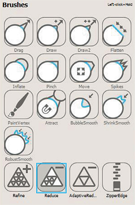
LOCALLY REDUCE AND ENLARGE THE MESH WITH MESHMIXER
Import a sphere into Meshmixer. In the “Sculpt” tool, choose the “Reduce” brush.

Adjust the strength of the tool to 90 and do the same with its size.
With the help of your mouse, facet half of the sphere in such a way that the triangles are very obvious. To help, enable the display of the mesh (Wireframe) with the W key on your keyboard.

For the second half of the sphere, use “Refine.” This tool will increase the mesh’s density to the maximum.

Cut the sphere in half with the “Plane Cut” function in a way that keeps the two resolutions visible. Export the file in STL then import it into your 3D printer’s software. Copy it three times. At a scale of 100%, 150%, and 200%.

Print the half-spheres with infill of 0% in full resolution (0.1 mm for most FFF 3D printers). You will observe that, although the change in the mesh is very visible on the half-sphere size at 200%, is is barely perceptible on the smaller piece.
You can understand the importance of calibrating and choosing the resolution of the mesh depending on the size, the geometry resolution, of the layers that the technology being used allows. If you are making the same three volumes with a DLP 3D printer with 16 microns of resolution, the bumps on the surface will be visible on each of the pieces.
REDUCING THE SIZE OF A FILE WITH MESHMIXER
For this exercise, you will be downloading a very high-resolution 3D model. We have chosen a hand digitized with an Artec EVA scanner. You can recover the 243 MB STL ASCII file, named “main_HD_cut_ascii.stl”, at the following address:
http://www.thingiverse.com/thing:440625
Open the file in Meshmixer. Before doing any modification, export it again, but this time as an STL Binary format. The size of the file should automatically be reduced to 44 MB, which is 6 times smaller than the original file.

Now, go into the “Select” tool and press the Control-A (or Command-A) keys to select the entire volume. Its color should automatically change to orange. Activate the “Wireframe” to help you visualize the grid (W shortcut).
In “Edit,” click “Reduce” or use the shortcut (Shift-R). First reduce by 50%, then export the result in STL Binary. The size of the file obtained should have been reduced to 22 MB.
Repeat the experiment with a resolution that is about 50% lower. Your file should now be around 11 MB. Study the transformations hapenning to the hand’s mesh. Make an additional reduction of another 50% to the 11 MB file. The size of your file must be less than 6 MB. Your original file has been divided by about 40. A fourth reduction by 50% will give you a file with the very acceptable size of about 2.5 MB.
The difference from the original file is still very subtle. With a fifth and final reduction, this time by 75%, you will begin to see a distinctly more faceted texture appear.
Your file is no more than 0.6 MB, 400 times smaller than the high-resolution STL ASCII. You can now visually compare your 243 MB file to the most recent obtained by importing them into the same project.

Do you see a difference?
If yes, import the two files into your 3D printer’s software. Begin a 3D print by using the same machine, the same consumable and the same resolution for the two pieces. You will notice that they have almost exactly the same appearance once you’ve printed them.

We rarely need large files to create objects with FDM/FFF 3D printing. However, it is interesting to have tighter mesh when you want to use more precise technologies, such as DLP or when you are creating photo-realistic images. You just have to find the best ratio.