

ARTICULATE
CREATE A VERTICAL PIVOT USING 123D DESIGN

PREASSEMBLED TOYS
One of additive manufacturing’s most significant advantages is its ability to produce objects with components that are fully-assembled and movable straight out of the machine.
Traditionally, injection-molded plastic objects are made following strict criteria of uniform wall thickness, release angles, and assembly tolerances. 3D printing, thanks to its method of building up successive layers, enables the creation of variable thicknesses, with no effect on the surface quality. As there is no need to mold, it also gets rid of the need to create draft angles to remove the finished object from the mold more easily. Assembly tolerances are still necessary, but in some cases, different parts of an assembly may be manufactured and joined simultaneously.
The elephant, robot, and car on these pages were made on a MakerBot Replicator without any support material. The elephant’s legs, head and trunk, like the wheels of the car, and the robot’s joints are movable straight out of the machine. Such objects can’t be created in one go with conventional industrial processes.
The following exercises will teach you how to create moving parts for manufacturing using FDM/FFF by creating pivot axes and bridges. These tips will eventually help you to imagine more complex articulated objects such as Makey the robot.

Articulated elephant toy
By: Samuel N. Bernier
3D printed on:Replicator 2
Source: Thingiverse
Thing: 257911
© Thomas Thibault
Makey the robot
By: Samuel N. Bernier
3D printed on:Replicator 2
Source: Thingiverse
Thing: 331035
© le FabShop
FabShop Mobile
By: Samuel N. Bernier
3D printed on:Replicator 2
Source: Thingiverse
Thing: 359008
© Tatiana Reinhard
CREATE A VERTICAL PIVOT USING 123D DESIGN
In a new 123D Design project, import a cube type using the “Primitive Box” function. Place its bottom left corner at the start of the grid.

Then select the “Polyline” located in the “Sketch” category, then draw a profile starting from the face of the box with the following dimensions:

Next, use the “Sketch » Offset” tool to create a +0.5 offset of the first sketch. Delete the box.

From this offset outline, create a second profile (shown in light blue in the next image) using the sketching tools. Make sure the top and bottom of the second profile line up with the first one.
Feel free to toggle the “Snap” function, found at the bottom right, to help you use the grid or the sketch as a guide. Use the “Sketch » Trim” tool to remove lines you don’t need. Then create a 1mm wide rectangle, enclosed within the second sketch.

Using the “Revolve,” function, found in the “Construct” tool, select the first profile and the newly drawn rectangle. For the axis select the whole left edge of the first sketch.

Revolve it 360 degrees:
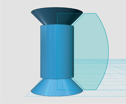
There must be a minimum gap of 0.5 mm separating the two parts to ensure that they move relative to each other after printing. Extrude the second profile giving it 1 mm on each side (2mm in total) using the “Construct » Extrude” function. You may have to move it 1mm to center it with respect to the revolved shape.

Then choose the “Circular Pattern” function in the “Pattern” toolbox.

Select the shape you just extruded as the “Solid” and the circular edge of the central part as the “Axis”. Give the function a value of 12. Now the fan blade should be duplicated 12 times:

Join the 12 fan blades to the cylinder crossing them by using the “Combine » Merge” function.

Using the “Shell” function in the “Modify” toolbox, select the top of the axis to create a cavity.

Give it a thickness of 0.8 mm. Finally, add a 2 mm chamfer (shortcut key C) at the base of the central axis. This will ensure the first layer of melted plastic (if FDM/FFF is used) dont spread and merge the two parts together.

Note that, for this model, the angles and spaces between the parts are designed to print the object using a single material filament without support. Start 3D printing your fan with the closed part of it down. Use the “Raft” function to stabilize the elements while production is taking place. If your FDM/FFF machine is calibrated correctly, the raft should detach without any problems and the object will rotate on itself.

It’s best to avoid changing the scale of preassembled objects such as this one, because the tolerances that allow play between the components could become too tight or too loose.
CREATE A BRIDGE
In fused filament 3D printing, pivot assemblies are not limited to vertical axes. It is possible to create hinge and chain effects due to the FDM/FFF’s ability to connect the horizontal distance between two points without support material. This feature is called “Bridging”.
It is thanks to this trick that the axes of the elephant’s legs and head (see page 77) could be created. It’s also thanks to this that the Makey robot’s legs are articulated.
To see the principle up close and live, here’s a simple model that will make you a “Bridging” guru.
Begin by drawing a 50 mm wide square in 123D, using the “Sketch rectangle” tool, following the grid on the work area.
With the “Offset” tool, create a second square, offset by 5 mm, inside the first.


Using the “Extrude” function, select the frame created and make it 50 mm high.

Use the “Sketch Rectangle” tool again to draw a 40 mm wide square centered on the front face of the hollow cube.

Select this new outline with the “Extrude” function, then by choosing a negative offset, extract the material throughout the object.

Repeat the last two steps for the side view. Only the edges of the cube will remain.

Add 2 mm rounded corners on each of the cube’s inside edges. This sometimes help getting better bridges. Copy and paste the cube frame and scale it down to 75%. Then copy and scale this new cube down another 75%. All three cubes will be inside of each other. Now, we need them to lay on the same surface. For that, we will use the “Snap” tool and select the bottom surface of each cube.


In your 3D printer’s software, import your cube and copy it once with a scale of 75%. Then copy the new cube with an additional shrinkage of 75%, so that the three shapes can be nested. Make sure they are sitting flat on the work area. Some 3D printer software might not enable imbricated parts, when coming from seperate STLs. In this case, try doing it directly in 123D or Meshmixer. If you are a cheater, download the file directly from here:
http://www.thingiverse.com/thing:440375
Start the print and observe what happens at the end of each cube. Some filaments may float in the air, but normally each cube edge should be completed.