

3D MODELING
MODELING USING “PRIMITIVES” ON 123D DESIGN
DIFFERENT APPLICATIONS USING “PRIMITIVES”
MODEL ON 123D DESIGN USING SKETCH FUNCTIONS

MODEL A HANDMADE GIFT
You’ve probably given a Play-Doh sculpture or a macaroni picture as a Mother’s or Father’s Day gift. These objects, although aesthetically questionable, remain throughout the years in attics and memory boxes, as we hold unique and handmade objects with particular affection.
The “Mobile for Joseph” is an example of a “gift 2.0”. In December 2013, the financial Director of LeFabShop became a father for the first time. So, his team of designers consulted with each other to figure out what gift to give him to celebrate the arrival of his newborn. The same day, a small mobile balanced by birds and clouds was created in the 123D Design software.
The initiative was documented then shared on the Instructables and Thingiverse websites so that the design could benefit hundreds of other infants and parents.
It takes a considerable number of hours of training to reach the level where you can produce an original idea in 3D. The mobile exercise is a first step in learning modeling for three-dimensional printing.
You can check out the original project on :
http://www.instructables.com/id/Birds-Mobile/

Joseph’s mobile
By: Samuel N. Bernier
3D printed on: Replicator 2
Source: le FabShop
© Tatiana Reinhard
Source: Thingiverse
Thing: 269088
Joseph’s mobile (birds)
By: Samuel N. Bernier
3D printed on: Replicator 2
Source: le FabShop
© Tatiana Reinhard
Joseph’s mobile (cloud)
By: Samuel N. Bernier
3D printed on: Replicator 2
Source: le FabShop
© Thomas Thibault
MODELING FOR 3D PRINTING
Several parameters exist that must be taken into account in order to create a “good” file compatible for 3D printing. Each case is unique, but there are some basic rules to follow in order to avoid unwelcome surprises at production time.
The object created on your software must have all of its surfaces closed in order to create a geometry whose interior and exterior are clearly defined. The term “watertight” is used to define this property. Problems with watertightness are very rare if you only use “solid” modeling functions on software like SolidWorks, 123D Design, Catia, or Inventor. On the other hand, you might make some mistakes if you’re a beginner on Rhino, SketchUp, or even Blender. A simple method to check the volume consists of visually examining all the seams of the 3D object and fusing the badly “sewn” surfaces. Some 3D software or their plugins simply won’t let you export a STL file if the geometry isn’t perfectly defined. Sometimes surfaces are completely reversed when imported into another software. In these cases, Netfabb Basic offers an automatic repair solution (see the exercise on page 45).
It’s important to know the scale on which the object will be made before rushing into modeling. Not every machine has the same printing volume. Determining the size of the printed object allows you to choose the machine to adopt or even to plan an assembly method in case you need to produce it in multiple parts. (see the exercise on page 54) This is particularly important for people working on an architectural scale. For example, a 3D file of a house modeled at its actual dimensions will probably have a problem of unprintably small thicknesses when it comes to the windows, handles and other details that, once scaled-down, will no longer be able to be printed. For example, a 10 cm wall at a 1:100 scale will only have a 0.1 mm thickness. For peace of mind, allow a minimum of 0.8 mm of wall thickness for most 3D printing techniques. Increase this thickness if you want to refine your piece or apply another finishing treatment (see page 134). The 3D printing service Shapeways, for example, asks for a minimal thicknesses of 2 mm for client files using powder sintering. In every case, it’s best to take precautions and avoid going below the recommended thicknesses.
In the case of FFF or FDM 3D printers, it’s interesting to take into account the opening of the extruder nozzle. Most “personal” or “office” 3D printers on the market are equipped with brass nozzles that have a circular hole 0.4 mm in diameter (regardless of whether the filament used is 1.75 or 3 mm). A line of material has, as a result, a width of 0.4 mm. If you print a hollow cylinder, its minimal wall will be 0.4 mm, like the case of the famous “Stretchlet” bracelet by designer Emmett:
http://www.thingiverse.com/thing:13505
Note that the scale of a 3D file can be changed at any moment and as often as necessary, whether it be directly in the modeling software, using the 3D printer’s software (MakerBot Software, Slicer, Cura...) or by means of a middleware (Netfabb, Meshmixer...).
MODELING USING “PRIMITIVES” ON 123D DESIGN
Download and install 123D Design:
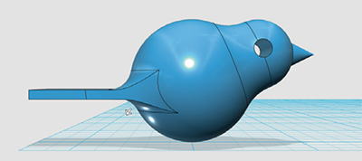
The 123D Design software from Autodesk is a great tool for creating simple 3D models. In addition, the use of solid modeling principles almost automatically insures the feasibility of the parts by 3D printing, as long as the bodies remain fused. Directly connected to other software of the suite, 123D Make and Meshmixer, 123D Design is the heart of a comprehensive ecosystem for digital manufacturing. This exercise will show you how to use primitive volumes to create a small bird in fused deposition modeling.
Open a new project in 123D Design.
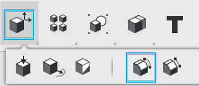
In the toolbar on the top of the interface, select “Primitives,” represented by a half circle hidden behind a cube.

Choose the sphere. Position this sphere at the origin of the grid (position 0,0) and give it a radius value of 14 mm.

Add a second sphere at 15 mm on the X axis of the grid then give it a radius of 8 mm.

Left click on this sphere, then select the “Move” tool among the options of the window that just appeared on the bottom of the screen.

Drag the up arrow and move the small sphere up to 12 mm. It should come in contact with the large sphere, representing the bird’s body.

Use the orientation cube (top right) to set your work area to Front view. Now import a cone, also one of the “Primitives” options, and place it at 25 mm from the large sphere, following the grid. Give it the following values: Radius = 3, Height = 6.

Then, select the cone by left-clicking. With the “Move” tool’s rotate icon (just above the arrow), spin the volume 90 degrees clockwise, then slide it vertically to 17 mm.

Then, import a cylinder 15 mm from the large sphere, still following the floor grid. Give it a radius of 2 while keeping its height.

Spin it horizontally with the “Move” function, then slide it vertically 11 mm from its original position so that the cylinder forms the bird’s eye.

Now use the orientation block on the top left to place your work area in plan view (Top). Insert the center of a primitive box at -20 mm in relation to the origin while giving it dimensions of 15 mm in length, 30 mm in width, and 2 mm in height. Go back to front view and move the box vertically to 10 mm so that it becomes the bird’s tail.

In the toolbar on top, select “Combine,” represented by one cube hiding a second. Three options will appear. Choose the first (Merge), symbolized by a cube fused to a circle.

Once the function is turned on, click on the bird’s tail, body, head, and beak. Then press the “Enter” key on your keyboard. The four volumes will now form just one.

Now, still with the “Combine” tool, use the “Subtract” function, second on the list. This time, first select the bird’s body in “Target Solid,” then the cylinder of the eye second in “Source Solid.” When you confirm the action with the “Enter” key, a hole should have replaced the cylinder.
All that’s left is to create the neck and the curves of the tail. For this, we’ll use the “Fillet” function, represented by a cube with rounded corners, located in the “Modify” tool. You can also use the shortcut key (E).
Select the ring between the head and the body, then give the function a radius of 10 mm. Keep the “Tangent Chain” option checked off. Your bird now has a neck.

Switch to Top view, then Fillet again, selecting the small edges on each side where the tail meets the body. Give them a “fillet radius” of 30 mm.

Use the filet function one last time for the semi-circular edges above and below the tail. Give the filet a value of 5.
Your bird is modeled. All that’s left is to create a form on which it can be attached. In the case of a “Mobile for Joseph,” the birds hook onto a wooden dowel 15 mm in diameter. We can repeat the technique we used to make the cavity for the eye. Unleash your imagination and then draw other forms that will let you hang it on other surfaces, like from the top your computer or even the tip of a pencil. Save your new friend on your 123D account or on your computer, but don’t forget to export a STL version for 3D printing!

In the “slicing” software of your 3D printer, a printing trick for the bird is to print the tail first so that it can be made without using material support. Thanks to its shape, it can also be built completely hollow with an “infill” filling of 0%. However, don’t hesitate to use the “Raft” function to stabilize your bird during printing. Otherwise, it may fall before being finished. To obtain a better resolution on small details, such as the bird’s beak, we recommend you throw several copies of the model on the same tray. This will allow the melted plastic to cool properly in between each layer.

DIFFERENT APPLICATIONS USING “PRIMITIVES”
To create the mobile’s clouds, import 3 spheres of different diameters (here 20 mm, 30 mm, and 40 mm).

Cluster 5 large spheres together by using copy and paste shortcuts and placing them randomly. Make sure not to leave any gaps in between.

Create 5 medium-sizes spheres and attach them to the others. If you want, use a third size.

With the “Merge” function, fuse all the spheres into a single volume.

Then, create a large box exceeding the clouds in length and width. Place it so that it runs across the lower portion of the clouds.
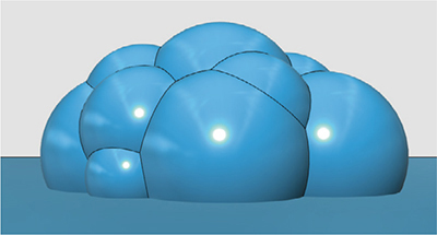
With the “Subtract” function of the “Combine” tool, subtract the box from the clouds. To make the model softer, use the filet function to round the edges at the base of the clouds. If needed, add some holes to hang them from the mobile.

When you’re satisfied with the shape of your clouds, send it directly to the 3D printer with the “3D Print” option located on the main menu.
Your file will open in Meshmixer and all that’s left for you to do is to orient it for printing.

MODEL ON 123D DESIGN USING SKETCH FUNCTIONS
Although using primitive volumes is sometimes very convenient, it’s often best to model using drawings to which you can apply extrusion, revolution and subtraction functions.
This small example shows how to create an elastic band used to hang the clouds from the wooden dowel mobile.
To begin, draw a circle 12 mm in diameter centered at the origin by using the sketch function “Sketch Circle.”

Using the “Polyline” tool, create a rectangle 2 mm large starting at 5 mm from the center and passing the circle another 5 mm.

Use the “Trim” tool to erase the lines inside the outline and at the left end of the rectangle.

With the “Sketch Filet” tool, create some curves with a 1 mm radius in between the circular and vertical sections.With the “Offset” tool, select the outline to create a 0.8 mm outer gap.


Go back to the “Polyline’ took to completely close the sketch. It should automatically be filled in light blue. This is a sign that the drawing can be used for a function.

In the “Construct” tool, use the “Extrude” function to give your drawing some volume by selecting it and giving it a value of 5 mm.


Now place your work plane into the Right view and use the “Sketch Circle” tool to create a circle at the center of the flat part. You must select a smooth surface to transfer the sketch plan there. Use the “Polyline” tool to find the center of the rectangle. Give the circle a diameter of 1.5 mm.
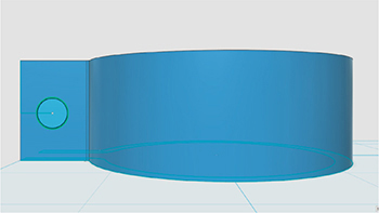
Using the “Press Pull” function, from the “Modify” tool, make a hole through the part. You can also use the P key as a shortcut. A red cylinder should appear as a sign of material removal.


You’ve made a technical part using drawings on 123D Design!

Special filaments such as Filaflex and NinjaFlex can be used to create flexible objects with a rubbery feel. However, an object can achieve flexibility through design techniques such as incorporating hollow shapes and thin walls.
The PLA bracelet linked here is a good example of a shape made flexible with simple design rules such as open contours and minimum thickness.
www.thingiverse.com/thing:445476
With 3D printers, it is easy to create objects nested inside each other like Russian dolls. The bridges exercise on page 82 is a good example. If we superimpose slightly conical parts in one file, we can get assemblies with telescopic movements!
This has been done in the following file:
www.thingiverse.com/thing:445481
