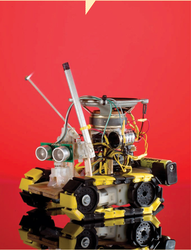
YELLOW
DRUM
MACHINE 
A couple of years ago I started getting into Picaxe microcontrollers, and I ordered a bunch of random components to experiment with. Turning these funny little spring-mounted motors on and off, I thought, Hmm — I could put a stick on that and let the microcontroller drum! This mini sound-recorder board? Hey, if the robot is drumming, it could record itself and play a new beat with the first one in a loop. Oh, nice yellow tracks, a rangefinder — cool, it could move around and look for things to drum on.
After that, the Yellow Drum Machine (YDM) practically made itself. Using hot glue and wooden sticks, it didn’t take me long to make a simple chassis, and after a weekend, the finished robot was driving around my house, making wicked beats on stuff it found.
START
1. Build the chassis.
Assemble the Gear Motor and Tread set into 2 tracks with 20 links each. Put a wheel on each motor and solder a 4" (10cm) lead to each motor contact (4 total, Figure A, page 44).

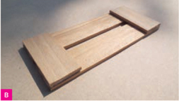
Make a flat wood chassis about 5½"×2¼" (14cm×5.5cm); it should be a bit longer than the tracks. I cut flat sticks into 4 pieces and glued them together (Figure B). You can also use more sticks, or a single piece of wood with a hole drilled in it for wires to pass through.
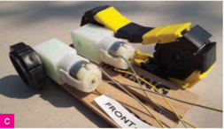
Flip the chassis upside down and affix the motors flat to its rear underside with double-sided tape (Figure C). Orient the motors so that the tracks will run parallel along the chassis without touching it or sticking past its rear or front edges. The motors themselves should sit at least ½" away from of the rear edge, to leave room for the GM10 “tail” motor (Step 3). Reinforce the join with 2 applications of hot glue, letting it cool in between.
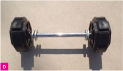
Prepare your front axle so its wheels will turn freely without touching the chassis. I used 2 washers on each side to space the wheels away from the chassis, and a metal screw hot-glued into each end of the axle to keep the wheels from falling off (Figure D).
Frits Lyneborg
BUILD A FUNKY LITTLE FREE-RANGE DRUMBOT THAT ROAMS, MAKES BEATS, AND SAMPLES.
Garry McLeod
See makeprojects.com/v/27 for suppliers, prices, and other sourcing information.
Picaxe-28X1 Starter Pack (USB) includes microcontroller in a project board with a programming cable
Motor driver chips, L293D (2)
Solarbotics GM10 pager gearmotors (4) These can only turn from side to side, not rotate fully around.
Sound recorder module (aka sampler board), 20-second such as item #PPM155 from techsupplies.co.uk, or #276-1323 from radioshack.com. The Tech Supplies module’s buttons both have wire pairs you can connect to easily. With RadioShack or other modules, you’ll have to solder a wire to button pads on the circuit board.
Speaker, 2", 16Ω
Ultrasonic distance sensor (aka rangefinder), 3-pin Devantech SRF05
Solarbotics Gear Motor and Tread Package, GM9 (143:1, 90° shaft)
Flat wooden sticks such as paint stirrers, popsicle sticks, etc.
Lightweight tubing or rod, fiberglass, carbon fiber, or hollow aluminum, about 1′ (30cm) for the “bass drum” (tail) and “snare drum” sticks
Lightweight fiberglass rod, very thin, about 6" (15cm) for the “hi-hat” drumstick
Aluminum or other tubing, ¼" (6.4mm) diameter × 4" (10cm) for front wheel axle. Use the same tubing as above or something heavier. I like to cut pieces from old radio antennas.
Metal washers (4) to fit over the axle
Battery holder (long), 4×AA (2×2)
Female-to-female jumper wires (15) Yellow is nice, to match your robot.
Wire, stranded, 18–22 gauge, 3'
Header pins, male, snap-off (4)
Heat-shrink tubing Choose colors to match your design.
Cable ties, various sizes and colors
Rechargeable AA batteries, 1.2V (4) These need to be 1.2V — standard 1.5V alkalines might fry your robot.
Epoxy, quick-setting
Adhesive tape, double-sided either foam or thin
TOOLS
Soldering equipment
Cutting tools for wood and wire
Lighter or heat gun
Screwdriver, small, Phillips for mounting motors
Hot glue gun and glue sticks (5)
Fine-gauge steel wire to hold sticks to the motor shafts while epoxying
Computer Windows, Mac OS X, or Linux
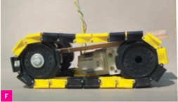
With the chassis still upside down, run the tracks around the wheel pairs. Push the axle forward (away from the motors) as you hot-glue it to the bottom of the chassis (Figure E). Try to get the tracks tight. The chassis will be tilted forward — that’s fine (Figure F).

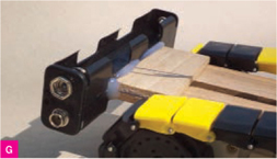
Mount the battery holder to the rear end of the chassis like a rear bumper, using a line of hot glue (Figure G).
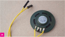
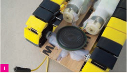
Test the sampler board with AA batteries to make sure it works (record your voice and play it back). Cut and strip one end of 2 female jumpers, then unsolder the sampler’s mini speaker and replace its 2 original wires with the jumpers (Figure H). Hot-glue the speaker under the chassis at the axle and run the jumpers topside (Figure I).
2. Add the head and neck.
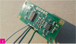
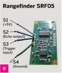
Solder 4 insulated wires, each about 4" (10cm) long, to the back of the SRF05 rangefinder, to all but the fourth pad along the bottom (Figure J). These are the board’s 5V, Echo Output, Trigger Input, and Ground contacts.
Epoxy the SRF05 “head” to a GM10 motor, perpendicular across the shaft and pointing away from the small pin sticking up, so the rangefinder can turn from side to side. During curing, I held the board and motor in place with putty and foam tape (Figure K), but you can improvise another way.

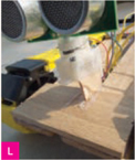
Mount the “neck” motor at the front center of the chassis so that the head stands vertical (or leans only slightly forward; not as much as the chassis) and the rangefinder “eyes” sit back 1/16" or so (2mm) from the front edge. I used a bit of wood just under ½" (10mm) to prop the front of the motor to let it sit level, then added liberal amounts of hot glue to secure it to the chassis (Figure L). Try to give the mount a small footprint.
Turn the head from side to side. It should look straight ahead when not touched, and if it moves much more to one side than the other, glue fiberglass rods or wooden stops vertically so that it turns about equally far to the left and right (Figure M, following page).

3. Add the drumsticks.
The robot has 3 drumsticks, each of which is mounted to a GM10 motor: a bass drum “tail” under the battery pack, and thick snare and thin hi-hat drum sticks in front, held by motors attached to wooden uprights just above and behind the rangefinder “head” on either side.
Estimate stick lengths by holding the motors in position and observing which way they’ll turn. The bass drum stick (about 2") should hit the ground at an 8 o’clock angle and the 2 front sticks (about 4" each) should be able to reach and drum on vertical surfaces 1" or so in front of the robot. Cut the sticks long, then trim them after seeing how they perform. Shorter sticks work better but look less cool, so you need to find a balance.
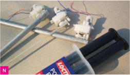
Pre-mount each stick to its motor. Drill a hole through thicker sticks to fit over the pin, and tie thin sticks on with wire. Epoxy the sticks in place (Figure N).
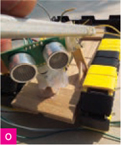
Mount the motors to the chassis, eyeballing where you think they’ll look good (Figures O and P). For the front motors, I hot-glued wood uprights onto the chassis and added triangular reinforcements in front and back. (No, I’m not sponsored by a hot glue company.) Check that the sticks can travel freely with the head and other sticks in all possible rotational positions (Figure O).

4. Mount the boards and large speaker.
To prepare the Picaxe board, plug one of the L293D motor controller chips into the onboard 16-pin socket, making sure the notch at one end of the chip matches the marking on the board. (Bend its pins to fit the socket by pressing the chip down sideways on a table.) This chip will control the track motors.
Snap off and solder 2×2 male header pins into the 4 holes marked A and B on the board.
It’s time to mount the microcontroller, sampler, and larger, cool-looking speaker.
Using more flat sticks and hot glue, I made 2 dividers running fore and aft along the right side to separate the microcontroller and sampler boards and hold them upright on edge (Figure Q). Note that the Picaxe board’s programming jack needs to be easily accessible. On the sampler board, cut off the battery clip, but leave its wires connected to the board.

Then I added a pillar on the left side and a roof to enclose the boards and support the large speaker on top, pointing up.
5. Wire the rangefinder, motors, and microcontroller.
Now let’s wire everything up. Figures R–T show the wiring points for the rangefinder, microcontroller board, and external motor controller chip (for the neck motor). Connect these components with wires, following the Connections list. (Save the sampler board for later, because you need to test it first to determine how it should connect.)

» You can connect voltage wires (V) to any +5V point, and ground wires (G) to any Ground point, whatever is closest or easiest.
» Connect wires to the rangefinder and external chip by soldering and insulating with heat-shrink tubing. Make connections to the AXE20 board by plugging in female header wires. Make your own female headers by cutting female-to-female jumpers in half and soldering each half to a plain wire if more length is needed. (You can also connect ground wires to the AXE20 board via the solderable pads along one edge.)
» Connect the motors (tracks, drums, and neck) either way for now. You’ll run test routines later and swap the 2 connections to any motors that run backward.
CONNECTIONS
Right and left track motors: Connect to the onboard motor controller — left motor wires to the 2 MA pins on the main board, and right motor wires to the 2 MB pins. You’ll swap pins later if motor direction is reversed.
Rangefinder: S1 to +5V, S4 to Ground, S2 (Echo) to microcontroller I1, S3 (Pulse) to I0. The code converts pin I0 to an output, so it can trigger the pulse.
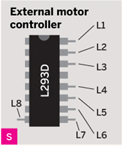
External motor controller: L1, L7, and L8 to +5V, L4 to Ground, L2 to I6, L6 to I7. The code converts pins I6 and I7 into outputs.
Neck motor: To external motor controller L3 and L5; swap them later if they’re reversed.
Drum motors: Snare drum motor to O1 and Ground, hi-hat motor to O2 and Ground, bass drum motor to O3 and Ground.
Small speaker (under chassis): O0, Ground.
6. Wire the sampler board.
You already cut off the sampler board’s battery clip and speaker, but it still has a microphone, an LED, and Record and Play buttons connected by wire pairs. Mount female headers on the black and red wires that connected to the battery clip, then plug red onto a +5V pin on the main board and black onto a Ground. Mount the larger speaker on top of the robot, pointing up, and solder the 2 sampler board speaker wires to it.
Insert batteries in your robot and test that the Record and Play buttons still work. Cut the Play wires close to the button and touch one of them to Ground on the main board. Does it play back? If so, this is the wire you’ll need, and you can trim off the other one close to the board. If not, try the other. (With some samplers, you’ll remove the Play button, test its pads on the circuit board, then solder a wire to the pad that works when connected to Ground.) Do the same with the Record button — find the wire that works when touched to Ground, and cut the other one away.
Mount female headers to both wires, then connect the Record wire to I2 on the main board and the Play wire to I3.
Mount the microphone and LED somewhere nice and visible. Now’s the time to be creative with extra little decorative parts. (I found a shiny plastic ring that works well holding the microphone.) To tidy up, use cable ties and hot glue, and you can also shorten wire lengths.

Garry McLeod
7. Program, test, adjust, and play.
At this point, you should have a nice little robot. Now it’s time to give the robot its program. Download and install the Picaxe Programming Editor or AXEpad (depending on your computer OS) from rev-ed.co.uk/picaxe/software.htm, if you haven’t already.
Launch the software, then open the Mode and Ports tabs under the Options panel to specify the type of chip (28X1) and the COM port for your computer’s USB.
Switch the main board off (remove a battery) and connect it to your computer using the Picaxe programming cable. Download the code files from makeprojects.com/v/27.
Each motor has a test code file in the test directory. Open each in the programming editor and click Program to compile and upload it to the microcontroller. Replace the battery and check that the motor behaves as it should, as described at the top of the test code, or swap its wires if it runs in the reverse direction.
The test runs will also guide you in trimming the sticks to adjust their balance. The sticks should be light enough for the motors to move easily, but with fiberglass or carbon fiber rods, it might help to epoxy a small bolt or screw at the end, to make the strikes louder.
With all the motors tested and wired properly, compile and upload the final code, ydm_ default.bas. Place the robot on a hard surface and power it up; it should look to the sides and begin driving around. After some time, it may feel it’s time to get funky. It will then search for an appropriate item (like a wall) to drum on. Eventually, it will find an object it likes, then tap a little beat on it.
The Yellow Drum Machine will record its drumming, then play it back in a loop while drumming more and making clicks from its lower speaker to the beat. Meanwhile, it also makes dance motions with its head and body.
While the robot records itself, it will also record your voice or other nearby sounds and include them in its tune. This is especially entertaining for kids. Play a musical instrument to “jam” with the YDM, letting it record and play back your riffs as an accompanist.
The BASIC software is written for modifying and playing. All parameters can be reset, and notes at the top and comments throughout explain how everything works. So you can make the YDM drum only when you enter the room, or use it as a platform to do a lot of other things. You can even make it draw.
Frits Lyneborg is co-host of “The Latest In Hobby Robotics” (blog.makezine.com/video) and runs letsmakerobots.com, the largest online community of its kind, which he started in 2008 as a forum for robot electronics, programming, and funny ideas and inspiration.