TEACHING
OLD TOYS
NEW TRICKS
Watching an animated robot is certainly amusing, but interacting with a robot is an experience! You can make interactive robots with unique personalities out of many common toys, and I designed the EZ-B Robot Controller (ez-robot.com) to make the process as easy as possible. This tutorial will introduce how the EZ-B works, and then explain how you can use it to teach an old Digger the Dog pull-toy some new tricks: autonomously chasing a red ball and obeying voice commands.
The EZ-B is a microcontroller circuit board that connects to numerous inputs and outputs. Put one inside a toy, and it will control servomotors, sensors, speakers, LEDs, and other devices that enable your bot’s behavior.
Meanwhile, the EZ-B also connects wire-lessly to a nearby computer using the Bluetooth protocol. Unlike with other microcontroller boards, all the programming and computational “heavy lifting” with the EZ-B happens on the PC side, and the onboard microcontroller just acts as a slave interface to your robot’s motors, sensors, and other peripheral devices. This lets your robot perform voice recognition, speech synthesis, visual feature detection, and other functions far beyond the capability of standard microcontrollers, and it also means you never have to compile or upload new firmware.
Plug-In Peripherals
The EZ-B circuit board has the same general pin arrangement as an ordinary Arduino microcontroller, but instead of connecting the microprocessor chip’s I/O pins to single female headers for plugging wires or shield pins into, it breaks them out into 3-pin rows, each with their own voltage and ground.
This lets you solderlessly plug in hobby servomotors with their standard 3-wire female plugs (red = power, black = ground, and white or yellow = signal/data).
Many Arduino-compatible sensors and peripherals also use this type of connector. On the sensor (inputs) side, these include distance sensors, tilt sensors, compasses, thermometers, button pads, and joysticks.
Popular effector components (outputs) with 3-wire plugs include servomotors, H-bridge adapters for motor control, and high-voltage relay adapters (Figure A).

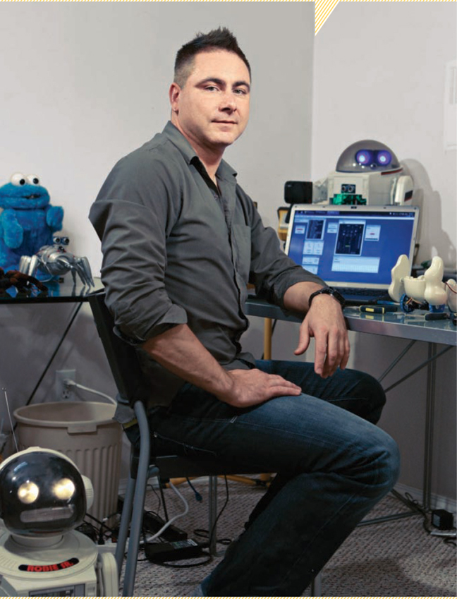
DJ SURES CONVERTS TOYS INTO SURPRISINGLY CAPABLE ROBOTS.
Colin Way
With the included female-to-female header adapter, the EZ-B is compatible with any Arduino shield. In addition, it has a header for I2C devices, which use 4 wires: power, ground, clock, and signal. This protocol, which is gaining popularity in robotics, lets you chain together multiple low-speed peripherals, ranging from servos to programmable LED modules (like the BlinkM RGB LED), and communicate with each in the software by using its unique address.
The EZ-B also has built-in protocol support for MIDI, iRobot Roomba control, and TellyMate serial-to-TV control.
For powering a robot’s wheels or tractor treads, you can often use the toy’s original motors and gears. Otherwise, you’ll need a gearmotor (or DC motor and gear set), or a continuous-rotation servomotor. Plain DC motors spin too fast, and the gears decrease motor speed while increasing torque. Continuous-rotation servos are variable-speed forward/reverse motors that use 3-wire servomotor connectors.
For robot joint movements and other animations, (e.g., to control head/camera position), you’ll use servomotors. You’ll most likely need to replace a toy’s original servos, if it has any, with generic hobby modules. Servos make precise movements within a range of 90° to 120°, specified by software. Small servos are fragile, so be careful with them; rotating their shafts manually can strip the gears and render them useless.
Distance sensors are favorite robot input peripherals that can typically detect >1"-wide solid objects from ≅ 2" to 30" away. Ultrasonic sensors, like the Satistronics HC-SR04, are less effective with angled or textured objects, while infrared rangers, like the Sharp GP2D12, are less effective in sunlight, so many robot builders combine both.
On the host computer side, the EZ-B software reads from the computer’s USB port in addition to communicating with the EZ-B controller via Bluetooth. This lets you pack more functionality into your robot by using 2.4GHz wireless USB devices, which don’t interfere with Bluetooth. For example, you can install a wireless camera onboard your bot and plug its wireless dongle into the host computer to have your EZ-B program process the live video feed. By using a 2.4GHz wireless USB hub, you can support both a camera and a sound card (to give your bot better sound), along with any other USB peripherals.
MATERIALS
See makeprojects.com/v/27 for recommended suppliers, prices, and other sourcing information.
Toy with moving parts
EZ-B .NET Bluetooth Robot Controller V3 $119 from ez-robot.com
Computer running Windows 7 or Vista, with Bluetooth transceiver
Batteries, AA (5)
2.4GHz wireless camera I got one on eBay for $19 with an embedded battery that charges off USB.
GWS modified servos (2)
Servo horns (2) star-shaped attachments for mounting
Small screws
Optional, for LED and speaker connections: Servo extension wires (2) LED
TOOLS
Dremel with cutting wheel Screwdrivers, small Sharpie
Masking tape or label maker
Optional, for LED and speaker connections: Soldering iron and solder
The EZ-B has an SDK (software development kit; ez-robot.com/sdk) that supports development for the controller within the larger EZ Robot Project. Community contributors have developed EZ-B software modules for a growing number of peripherals and sensors, letting you control these devices from the EZ-B without worrying about the low-level electrical details of the connections.

START
1. Set up your environment.
With any robotics project, you’ll want to focus on the creative side. So before you begin building your robot, create a quiet, comfortable, and clutter-free workspace where your ideas can flow.
It’s discouraging having to stop midway because you’re missing some supplies, so make sure you have enough hot glue sticks and a variety of screws, nuts, and bolts around. (Keep leftover screws from any toys you modify, along with any reusable lights, motors, gear sets, springs, and switches.)
If you’ll be Dremeling hard plastic, be prepared for a mess of shavings, and make your cuts outside or in a room with easy vacuum access and no carpet. If you’ll be working on a table, cover it with cardboard first. This prevents scratches and messes from the hot glue gun, and is also handy for making quick sketches or notes.
2. Find a toy.
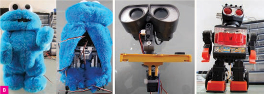
Browse thrift stores or revisit your old toy box, and find a toy that has moving parts and good robot-control potential. These can be robots, vehicles, animals, or even dolls (Figure B). I should warn you, however, that converting a doll into an animated robot may result in disturbing some of your friends.
The toy that leaped out at me when I was hunting for ideas for this article was Digger the Dog, a $7 pull-toy from Playskool. Here’s how you can get Digger to chase a red ball and obey voice commands, and you won’t even need to solder or write any code. The toy doesn’t even have a motor, so it’s also a great example of how to add autonomous mobility.
Take a good look at the toy you’ll be modifying. Study its limbs, head, and any other movable parts, and decide what you want to control. Animating arms, head, and other parts that require precision positioning will require servos. As a beginner, start small by adding basic movements. You’ll be able to add more features as your robotics experience grows. Practice makes robots!
The most common mechanisms for hobby robot mobility are wheels or tracks. Making a robot that walks is too complicated to explain in this tutorial, unless you start with a toy that already walks via a wheel-driven shuffle motion. In that case, it’s easy. To make a stuffed animal walk, you can wrap its “skin” over the shell of a modified walking robot toy.
If you already have your motors and other components, hold them against the toy in order to help you visualize where you’ll need to modify it and how to mount everything. With hobby servos, it helps to snap photos of available mounting brackets and motor shaft attachments at the hobby shop, and then refer to them while browsing toys. This minimizes buying hardware that you don’t end up using.
3. Add the servos.
Most toys use small Phillips screws, so make sure you have some small screwdrivers. Keep each type of screw you remove in a different small container to avoid confusion when reassembling. Digger had 6 screws under its belly, which lifted off to expose an open area perfect for housing the robot controller and battery (Figures C and D).


The toy may be a little dirty if you purchased it from a thrift store; if so, you can put the plastic parts in the dishwasher once they’re dismantled. Remove the pull-rope leash connected to Digger’s collar; you won’t need it anymore.
Hold the servos and sensors to the desired mounting positions and sketch with a Sharpie marker any cuts or drill holes before you start modifying the toy shell. Follow the carpenter’s rule: Measure twice, cut once!
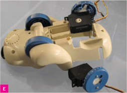
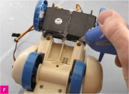
With Digger, the servos could fit back-to-back in the rear axle area, provided that the rear wheels were pushed out a bit wider than they sat in the original toy. So I removed Digger’s rear axle, dug plastic out of its body underside to make room for the servos, and dug out the rear wheels to accommodate the servo horns (Figure E). I also trimmed back the nose to expose the camera lens.
I secured the servo horns to the wheels with small screws saved from previous toy builds, then hot-glued the servos in place (Figure F). To avoid lopsided wheels, double-check their alignment with your servos.
![]() TIP: If you make a mistake, wait for the glue to dry and use a drop or two of rubbing alcohol to separate.
TIP: If you make a mistake, wait for the glue to dry and use a drop or two of rubbing alcohol to separate.
For mounting nearly all peripherals, a hot glue gun will be your best friend. Fit and hold the servos and sensors against the modified area of the body. Does it look OK? Great! Use a few drops of glue at first, verify the fit, and then go wild and add glue from all available angles.
4. Add the speaker, LED, and camera.
For any peripheral devices that don’t have 3-pin connectors, including any LEDs, speakers, and other devices that you liberate from the toy itself, I like to add servo connectors to make them easily pluggable. To do this, cut the male end off a servo extension cable and solder to your peripheral, referring to its datasheet to find its power, ground, and signal contacts. For LEDs, speakers, and other 2-wire devices, connect just the signal and ground.
For any other LEDs, springs, washers, mounting hardware, or screws that you liberate, this is a good time to start your collection of miscellaneous hardware.
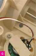
If you want to connect the speaker, unscrew it, then unsolder its 2 wires and replace them with a servo extension cable, soldering its white/yellow and black wires to each contact (Figure G).
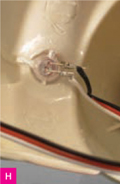
For the LED, wire another servo cable to the LED, black (ground) side to its cathode, which is indicated by the shorter leg and flat part of the plastic. Glue the LED into the hole in the top of Digger’s collar, where its leash used to connect (Figure H).
To help you during assembly and in the future, label the cables and plugs of all your peripherals using a label maker, or just masking tape and a marker. Label each servo by its position (right/left) and each sensor by its type. For Digger, we have a left servo, right servo, speaker, and LED.
For the camera, unscrew its case and remove its internal workings. Doing this with any peripheral device saves room, making it easer to fit. Use hot glue to lightly secure the camera inside the toy shell, with the lens pointing out of the nose hole (Figure I). Don’t use too much glue, as you may want to realign the camera or reuse it later in a different project.

5. Final assembly.
Determine the mounting position of the robot controller and battery pack. With Digger, its belly area was the perfect width to host the EZ-B Controller with the battery underneath. Refer to the EZ-B manual to determine the connection points for each servo and sensor.
Digger’s left servo plug is connected to pin row D14 and the right servo is connected to pin row D13. The speaker signal and ground are connected to D7. The LED anode is connected to the signal wire and the cathode to ground on pin row D6. Keep track of all of these connections; you’ll need to know them when configuring the software.
Once the connections are completed, carefully reassemble the shell, trying to protect the controller connections and any other fragile parts (Figure J).

To give your robot a unique look, you can paint the shell. Scuff the smooth finish with sandpaper and then clean it to allow the paint to bond. I painted over the Playskool doggy tag with red paint, then replaced it with an EZ-Robot label from our trusty label maker. You can also paint the entire shell a custom color. Bring it to a paint store and ask them what type of paint and process they suggest.
6. Connect to the PC.
Right-click the Bluetooth icon that should appear in the System Tray and select Add Device to bring up a listing of nearby Bluetooth devices. Power on the EZ-B, wait for the PC to discover it, then select the device and press Next. When prompted for a pairing key, select Provide A Key and enter 1234. Your computer should add the EZ-B connections as 2 COM ports. Note the lower numbered port; this port will carry the data connection between the PC and the EZ-B.
Download and launch the EZ-Builder software from ez-robot.com/ez-builder. This is the application through which you can program your robot (you can also use Visual Studio .NET, msdn.microsoft.com/en-us/vstudio). Under the Add Control menu, choose Connection, specify the COM port just noted when you established the Bluetooth connection, then click Connect. Then select Servo (also under Add Control) to specify the left and right servo connections at pins D14 and D13, respectively.
Time for our first test. From the Windows menu, add a Modified Servo Panel to your workspace. Press Config and select the Left and Right modified servo ports, then press Save. If all’s well, you should now be able to drive Digger around by clicking the arrow buttons or using the arrow keys on the keyboard.
7. Configure ball-following behavior.
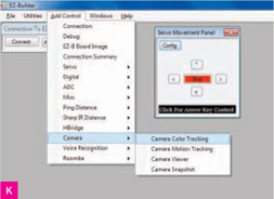
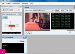
If your mobility was a success, install your camera’s driver on the PC. Click Add Control → Camera → Camera Color Tracking (Figure K). Your camera should appear in the Video Device dropdown list. Select your camera, then put the ball in front of the lens. Select the ball’s color from the next dropdown box (I picked red) and adjust the Color Brightness slider at bottom right until you can only see the ball in the preview window. (A bright room or sunlight works best for color camera tracking.)
To translate the color tracking into motion tracking with the servos, go back to the Servo Movement Panel, click the Config button, and enable Motion Tracking. Then return to Camera Color Tracking and check the Enable Forward Movement box. This will make the robot move forward when the detected colored object is directly in front.
Now you have a robot dog that follows a red ball (Figure M). You’ll almost certainly be entertained for a while, but what if the ball is out of view? Instead of having to steer Digger around manually, you can get it to respond to voice commands.

SMART DOGGIES
![]() Fig M: Formerly dumb Digger the Dog now moves autonomously, follows a red ball, and obeys voice commands, thanks to his EZ-B robot brain.
Fig M: Formerly dumb Digger the Dog now moves autonomously, follows a red ball, and obeys voice commands, thanks to his EZ-B robot brain.
8. Configure voice recognition.
EZ-Builder lets you access the Voice Recognition functionality that’s built into Windows 7 or Vista operating systems. To do this, click Add Control → Voice Recognition, and then click the Config button. This opens a grid in which you can enter words or phrases to be recognized on the left, and add corresponding script commands on the right, dragged from a menu of possible commands at far right. Add commands like Forward, Back, Left, Right, and Stop, and you can now verbally control your robot (Figure L)! You can get creative by adding phrases such as “How are you?” and have the robot respond with bleep bleep noises, or use the operating system’s built-in speech synthesizer to reply, “I am doing great, thank you for asking!”
If you have trouble with the voice recognition not hearing your voice, check the recording settings for your sound card in the control panel. The volumes for recording may be either too low or high. There is a wizard in Vista and Windows 7’s control panel that you can use to set up the voice recognition. Those settings will be carried over to EZ-Builder.
Going Further with Your Bot
The reward of interacting with your first robot is exciting, and you can easily build on it by adding new sensors and EZ-Builder controls. Once you’ve tested each peripheral to confirm that it behaves correctly, you can create custom scripts to give your robot a unique personality. For example, you can script your robot to turn left if the distance sensor returns a value less than 8". The tutorials and community forum at ez-robot.com are great places to obtain assistance and share.
Because large corporations have no control over robotics, we’re experiencing a great age of revolution. Today’s hobby robots will, we hope, be refined into superior robots of the future. I created the EZ-Robot project to inspire and exercise your creativity, and I hope you’ll share your creations with the community. The future of robots begins with your imagination!
![]() See Digger and the other toy-robots in action at makeprojects.com/v/27.
See Digger and the other toy-robots in action at makeprojects.com/v/27.
Colin Way
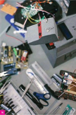
![]() Fig N: The author’s award-winning, scratch-built K-9 robotic dog (faithful companion to TV’s Doctor Who) was the basis for the EZ-B Robot Controller. K-9 avoids obstacles, follows people using onboard 3D mapping capabilities, synthesizes speech, and changes his personality based on human interaction.
Fig N: The author’s award-winning, scratch-built K-9 robotic dog (faithful companion to TV’s Doctor Who) was the basis for the EZ-B Robot Controller. K-9 avoids obstacles, follows people using onboard 3D mapping capabilities, synthesizes speech, and changes his personality based on human interaction.
DJ Sures is a roboticist who lives in Calgary, Alberta.