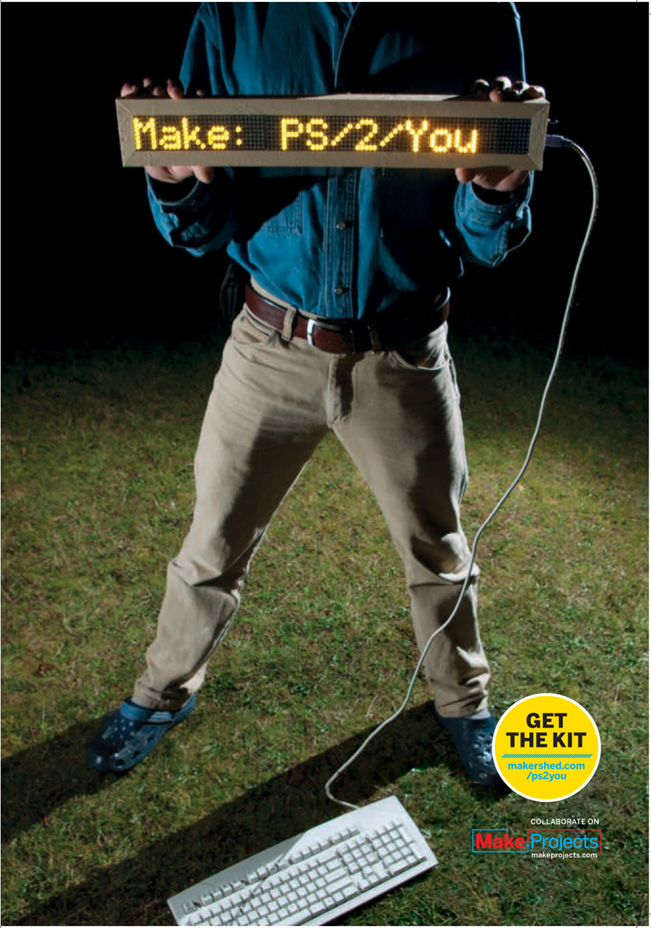
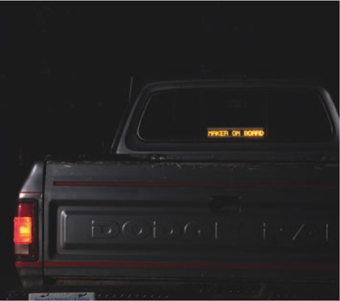
PS/2/YOU
Go-anywhere, instantly updatable glowing digital message board.
It all started with a small LCD salvaged from an old printer. I recruited my code-savvy older brother, Adam, and we soon had the LCD displaying text from an Arduino microcontroller. This was neat, but it was inconvenient having to plug the Arduino into a computer for reprogramming whenever we wanted to change the text.
We needed something for inputting the text, and it didn’t take long to find a PS/2 keyboard code library for Arduino — which confirmed my observation that anything that communicates with wires has probably been hooked up to an Arduino. I salvaged a PS/2 port from an old computer motherboard, and after some trial and error, we could plug in a common PS/2 keyboard ($5 new) and type messages directly into the Arduino and out to the LCD.
The LCD was so small, however, that hardly anyone noticed our witty remarks. We needed a bigger display. After looking at many appallingly priced commercial LED matrix products, we found a new and much cheaper offering: Sure Electronics’ 8×32 display boards. They cost $9 each and you can cascade up to four into one long display. We ordered three, and by the time they’d arrived, the Arduino community had already produced a library to run them. (Our code is based on two open source Arduino libraries: PS2Keyboard, by Christian Weichel; and MatrixDisplay, by Miles Burton.)
The result is our PS/2/You system, which displays keyboard-typed messages in 2"-tall LED letters that can be read from quite a distance. You can store and switch between six different lines of text, and it automatically scrolls through lines that are too long for the display. Power comes from an AC adapter or six AA batteries for portable operation, and the whole thing is housed in a sturdy wooden frame.
Immanuel McKenty is an 18-year-old home-schooler. Among other things, he rather enjoys taking things apart, and sometimes even manages to get them back together again.
SET UP: p.95 |
MAKE IT: p.96 |
USE IT: p.103 |
Island Light Photography
LOOK, MA — NO COMPUTER!
Rob Nance
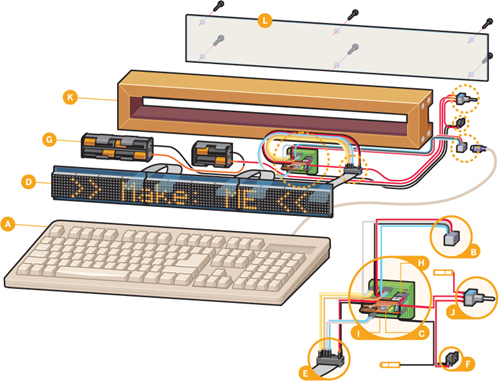
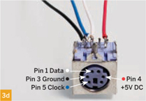
![]() With each key press and release, a PS/2 keyboard sends a “scan code” identifying the key over its data pin (pin 1).
With each key press and release, a PS/2 keyboard sends a “scan code” identifying the key over its data pin (pin 1).
![]() The keyboard plugs into a PS/2 port, which breaks its pins out into connectable contacts.
The keyboard plugs into a PS/2 port, which breaks its pins out into connectable contacts.
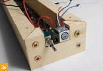
![]() The PS/2 port connects to an Ardweeny microcontroller, an Arduino clone, which interprets the scan codes. For character key inputs, the software looks up the corresponding 5×7 glyphs, then writes them via ribbon cable. The Enter key toggles between Input and Output modes.
The PS/2 port connects to an Ardweeny microcontroller, an Arduino clone, which interprets the scan codes. For character key inputs, the software looks up the corresponding 5×7 glyphs, then writes them via ribbon cable. The Enter key toggles between Input and Output modes.
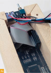
![]() Three 8×32 LED modules display the glyphs sent from the Ardweeny. Data is transmitted serially over a single wire.
Three 8×32 LED modules display the glyphs sent from the Ardweeny. Data is transmitted serially over a single wire.
![]() Ribbon cables carry outputs from the Ardweeny to the display modules one by one, in a “cascade” configuration that acts as one 8×96 pixel display.
Ribbon cables carry outputs from the Ardweeny to the display modules one by one, in a “cascade” configuration that acts as one 8×96 pixel display.
![]() A 9V–12V AC wall adapter provides plugged-in power.
A 9V–12V AC wall adapter provides plugged-in power.
![]() Six AA batteries power the display for on-the-go operation.
Six AA batteries power the display for on-the-go operation.
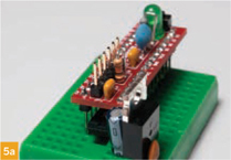
![]() A voltage regulator and filtering capacitors pare the voltage from batteries or wall wart to the circuitry’s required 5V.
A voltage regulator and filtering capacitors pare the voltage from batteries or wall wart to the circuitry’s required 5V.
![]() A mini solderless breadboard holds and connects all the circuit components and wires.
A mini solderless breadboard holds and connects all the circuit components and wires.
![]() An SPDT (single-pole, double-throw) switch selects battery power, plug-in power, or power off.
An SPDT (single-pole, double-throw) switch selects battery power, plug-in power, or power off.
![]() A custom wood enclosure holds all the components.
A custom wood enclosure holds all the components.
![]() A plexiglass back cover keeps the components inside while letting curious spectators marvel at the geeky goodness.
A plexiglass back cover keeps the components inside while letting curious spectators marvel at the geeky goodness.
Dot-Matrix Font Glyphs
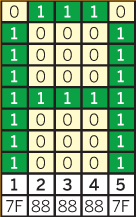
In the MatrixDisplay code library, font glyphs for the PS/2/You are stored in a multidimensional array of hexadecimal values (base 16). Each character of the font corresponds to one line in the array. As an example, one line looks like this:
{0x7F, 0x88, 0x88, 0x88, 0x7F},
This sequence represents the capital “A” character. Convert the hex values into binary, write them vertically from top to bottom, and you get a 5×8 array of 1s and 0s. Convert these bits to On and Off LEDs, and you’ll see your big “A” up in lights.
The PS/2/You code actually only generates 5×7 characters, leaving the top row of LEDs unused — 5×7 is a standard size for LED matrix characters, and it allows more characters to fit on the display without looking overly elongated.
Hexadecimal |
7F |
88 |
Binary equivalent (1×8 LED column) |
01111111 |
10001000 |
Decimal equivalent (not that it matters) |
127 |
136 |
SET UP.
MATERIALS
See makeprojects.com/v/27 for suppliers, prices, and other sourcing information.
A. MAKE PS/2/You Kit item #MSPS2 from the Maker Shed (makershed.com/ps2you), includes items B–I below and all other electronic components, except batteries.
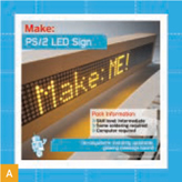
B. Dot matrix LED display modules, 8×32, with ribbon cable (3) Sure Electronics item #DE-DP106, about $9, or equivalent module. This item was recently discontinued but is available on eBay; see makeprojects.com/v/27 for alternative modules, drivers, and code.
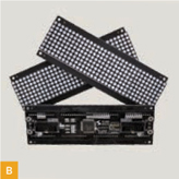
C. Computer keyboard with PS/2 connector They’re readily available at thrift stores. You can also use a USB keyboard with a USB-to-PS/2 adapter.
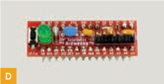
D. Ardweeny microcontroller
This small, cheap Arduino clone fits into a standard 14-pin DIP socket, but it doesn’t come with an onboard 5V voltage regulator or an FTDI USB-serial converter for programming.
E. 5V voltage regulator You can use a 7805, but the low-dropout LM2937 will make your batteries last longer, especially with lower-voltage NiMH AAs.

F. PS/2 port from an old PC mother-board; ask your local computer shop.

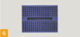
G. Solderless breadboard, self-adhesive, mini
H. Breadboard jumper wires (around 20, multiple colors), or solid core 22AWG wire Jumpers are easier to use and well worth the expense.

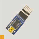
I. FTDI serial programmer such as the FTDI Friend, Maker Shed #MKAD22, $15
Gregory Hayes
» 9V–12V AC wall adapter can be found for $1–$2 at most thrift stores
» DC power jack to match your adapter probably a standard 5.5mm/2.1mm barrel jack
» Power switch, SPDT (on-off-on)
» Capacitor, ceramic, 0.1μF labeled “104”
» Capacitor, electrolytic, 10μF
» Batteries, AA (6)
» Battery holder, 2×AA
» Battery holder, 4×AA in a long, flat, 2×2 configuration
» Stranded wire, 22AWG, 4′ total We used red and black.
» Electrical tape or heat-shrink tubing
» Acrylic/plexiglass sheet, clear, 1/8 " thick, 21"×4" Lexan will work great but is more expensive.
» Wood screws, #8 flathead, 1¼" long (8)
» Wood screws, #8 pan head, ½" long (6)
» Wood screws, #6 pan head, ½" long (12, optional) see page 97
» Dimensional lumber, 1×4 (¾"×3½"), 4′ length, or 1×2 (¾"×1¾"), 8′ length see page 97
TOOLS
» Measuring tape or long ruler
» Handsaw or chop saw
» Table saw (optional) see Step 1g
» Chisel
» File
» Hammer or mallet
» Drill and drill bits: 5/64", countersink
» Screwdriver, medium
» Soldering iron and solder
» Desoldering braid or solder sucker
» Wire cutters
» Needlenose pliers (optional) handy for plugging in breadboard jumpers
» Multimeter
» Glue gun and hot glue
» Computer with internet connection and USB port
MAKE IT.

BUILD YOUR DIGITAL MESSAGE BOARD
Time: 3–4 Hours
Complexity: Moderate
1. BUILD THE FRAME
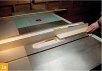
1a. Cut the 1×4 lumber in half lengthwise to make 2 strips about ¾"×1¾" (a nominal 1×4 is actually around ¾"×3½"). Use a narrow-kerf blade if possible.
NOTE: This frame fits the DE-DP106 LED modules; if you use alternative modules you’ll have to improvise a frame to fit them.

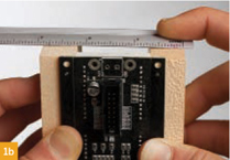
1b. Line up the 2 boards beside each other on a flat surface with their narrow edges up. Place one of the display panels facedown between the boards, so that the flanges on the panel rest on the boards, with the protruding LED matrix between them. Gently squeeze the boards snug against the sides of the LED matrix, and measure between the outside edges of the boards. This measurement is the length of the frame’s end pieces.
NOTE: The frame style isn’t crucial, so let your creativity (and materials) have a say in the design. I had a woodshop at my disposal, so I made something like an extra-deep picture frame with mitered corners and a slot cut in the long sides to hold the display panels.
1c. Use a chop saw or handsaw to cut a 45° angle on one end of each piece, oriented so the cut goes diagonally across the narrow edge. Measure 18¼" down the board’s length from the inner edge of the cut, and make a second 45° cut that angles back out. Repeat on the second board. These will be the 2 long sides of the frame.

Immanuel and Adam McKenty
1d. On each of the leftover board pieces, mark the distance measured in Step 1b down from the sharp, outside edge of the miter cut, along the longer face of the board. Cut one at 45° angled in from the measured length (the mirror image of the first cut), which will be each piece’s longest dimension. Don’t cut the other piece yet.
1e. Desolder the PS/2 port from its donor motherboard. Line up the DC jack, PS/2 port, and power switch atop the edge of the marked but uncut short piece of wood. Mark out a notch in the edge of the board just wide enough for all of them to fit next to each other and deep enough that the tallest component will sit flush.

1f. With a handsaw (or chop saw) cut the 2 edges of the notch. Make a few cuts to the correct depth in the middle of the notch, then chisel out the rest of the wood and file the bottom of the notch smooth. The ports and switch should slide into the notch easily but without extra space. Cut the second (notched) end piece as marked in Step 1d.


1g. Set the blade of your table saw to a depth of 5/16" (the size of the flanges on the display panels). Cut a groove lengthwise down the inside face of each long frame piece, ¼" in from the edge (preferably with a narrow-kerf blade).

NOTES: The panels should be able to slide into the slots and be roughly flush with the front of the frame.
If you don’t have access to a table saw, another way to make the frame is to cut two 1×2 boards (really ¾"×1½") to 18¼", and two shorter lengths of 1×2 to fit on the ends. Then, rather than cutting grooves for the display module flanges, use 12 #6 screws to secure the 3 modules onto the front of the frame through their pre-drilled mounting holes.

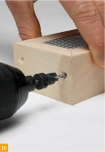
1h. Slide the 3 display panels into the slots in the long frame pieces, all oriented so that the writing on the printed circuit boards reads right side up as you look into the back of the frame. Fit and hold a frame end piece in place at each end, then drill E" pilot holes and countersinks for the 1¼" #8 screws that hold the frame together.
The notched end belongs on the left side of the frame as you read the circuit board backs, which is the right side as you view the front of the display. Put the screws in as you go to keep the frame together. Ensure that your countersinks are deep enough, and (to avoid splitting the frame pieces) don’t overtighten the screws. The frame is now finished!
![]() TIPS: Be sure to install the screws on the bottom edge of the frame at least 5/8" up from the bottom to avoid contact with the screws we’ll use to secure the back cover.
TIPS: Be sure to install the screws on the bottom edge of the frame at least 5/8" up from the bottom to avoid contact with the screws we’ll use to secure the back cover.
If you’d like, add some glue to the notched end of the frame for extra strength, but leave the other end unglued so you can unscrew it and slide the display panels back out.

2. CUT THE BACK COVER
2a. Place the assembled frame on top of the plexiglass sheet. Use a screw or other sharp object to scratch a mark around the edge of the frame.
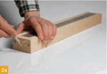
2b. Cut out the back cover with a handsaw, table saw, or the cutting implement of your choice. Line up the cut piece on the back of the frame and drill 6 pilot holes through the back cover material and into the frame itself. It’s now ready to be closed up once all the electronics are in place and functioning.

3. WIRE THE POWER AND PS/2 PORTS

3a. Wire the 2 battery packs in series by soldering the red (+) lead of one to the black (–) lead of the other.
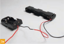
NOTES: The battery packs need to be removable for battery changes, so you can secure them in the frame using velcro, although the back cover and display panels seem to hold them in place nicely.
3b. Position the battery packs in the frame (I put them at the end opposite the notch). and lengthen the remaining 2 wires if necessary by splicing in stranded wire to let them reach the notch, where you’ll connect them to the DC jack and power switch. Insulate connections with electrical tape or heat-shrink tubing.
3c. Cut one end off a black breadboard jumper, and strip and tin the wire. Repeat with a red jumper. Solder the cut end of the black jumper and the black wire from the battery packs onto the DC jack’s negative terminal. Solder a short chunk of stranded red wire between the DC jack’s positive terminal and one of the outside contacts on the switch. Solder the cut end of the red jumper to the switch’s common terminal, and the battery positive to the free outside switch terminal.

If all went well, your switch should have an off position in the middle, a battery power position to one side, and adapter power on the other.
3d. Cut one end off 4 more breadboard jumper wires: red, black, blue, and white (or your equivalent). Strip, tin, and solder them onto the positive, negative, data, and clock pins on the PS/2 port (see pin diagram), and use a multimeter set to “continuity” to confirm the pin-wire connections.
I used blue for data wires, white for read/write and clock wires, yellow for the display panels’ “CS” wires, and red and black for power and ground — although I accidentally switched blue and white here on the PS/2 port. Having a consistent color scheme will make it much easier to figure out what’s going on.
3e. Dry-fit the PS/2 port, DC jack, and power switch again into the notch at the end of the frame. Heat up a glue gun and dab a bit of glue on each one before quickly pressing it tightly into the notch.
NOTE: This is admittedly an unorthodox way of attaching what would normally be PCB or panel-mounted components, but it’s very strong and relatively tidy — a good substitute when there’s no PCB or mountable panel nearby.
4. CONFIGURE THE DISPLAY PANELS
4a. Each LED display panel comes with a ribbon cable and has 2 ports on its backside that the cable will connect to.
Use 2 of the ribbon cables to chain the 3 panels together end-to-end by their adjacent ports. Plug one end of the remaining cable into the port closest to the switch and power jack. Fold this ribbon up tightly and use hot glue to attach its free end plug to an inner side of the frame, with its holes facing up toward the back of the frame.
![]() TIPS: Make sure the plug holes have enough headroom to let you plug in breadboard wires without their scratching the transparent back cover (once it’s screwed on). Also make sure there’s enough room between the glued-in plug and the board’s other ribbon cable port to accommodate the mini solderless breadboard.
TIPS: Make sure the plug holes have enough headroom to let you plug in breadboard wires without their scratching the transparent back cover (once it’s screwed on). Also make sure there’s enough room between the glued-in plug and the board’s other ribbon cable port to accommodate the mini solderless breadboard.
4b. Each LED display panel has a block of little DIP switches labeled CS1, CS2, CS3, and CS4. These switches determine how the microcontroller identifies each panel. The PS/2/You code numbers the displays left to right, looking from the front, so turn off all but switch 3 on the panel nearest the notch, all but switch 2 on the middle panel, and all but switch 1 on the panel at the battery end.
(To see what these switches do, set them to some other sequence once you have your display up and running.)

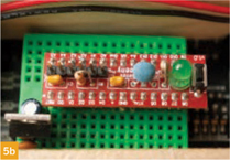
5. ADD THE ARDWEENY
5a. Plug your Ardweeny into the breadboard straddling the trench, with the green LED near the top, taking up the first 14 rows. Plug the voltage regulator into the bottom 3 rows on one side.
Plug the 0.1μF capacitor in between the voltage regulator’s input and ground legs (typically the sequence is IN-GND-OUT, going left to right looking at the front of the regulator, but check your datasheet to be sure).
Plug the 10μF capacitor’s positive leg in the regulator’s output and its negative leg (marked with a stripe) into the regulator’s ground bus.
NOTES: The mini breadboard has 17 rows, each consisting of an electrically connected 5-hole bus on either side of a central trench.
5b. Peel off the breadboard backing (exciting!) and stick it onto the flat, surface-mount Holtek chip on the back of the display panel closest to the switch and ports.
The ribbon cables each have 15 wires, and their plugs have 2 rows of holes that connect to odd-numbered wires along the top and even-numbered ones along the bottom.
5c. Since the voltage regulator’s ground bus is getting crowded by now, use a small jumper to extend it to an unused bus on the other side of the breadboard.
Plug the red power wire from the switch’s common into the regulator’s input bus, and the GND wire from the DC jack into the new ground bus. Use a red jumper to connect the regulator’s output to the Ardweeny’s power (labeled “+”) and a black jumper to hook the ground bus to Ardweeny GND.
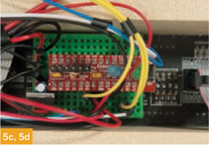
5d. Plug the PS/2 port’s power wire into the Ardweeny’s power and its GND into the Ardweeny’s GND bus. Plug the PS/2 port’s read/write wire into Ardweeny pin D3 and its data wire into Arwdeeny pin D7.
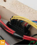
5e. Use jumpers to connect your components to the ribbon cable plug glued inside the frame. Note that the odd-numbered pins on the 2×8 plug run along the side with the small bump, opposite the side that the ribbon comes in.
To begin, connect CS2, the first wire on the ribbon (marked in pink) to Ardweeny pin D5. Connect CS3, the second wire, to D6, and ribbon wire 3 (CS1) to Ardweeny D4. For the display’s read/write input, connect ribbon wire 5 to Ardweeny D11, and for the data input, connect wire 7 to Ardweeny D10.
Finally, connect ribbon wire 15 to Ardweeny ground, and ribbon wire 16 to Ardweeny power. (You can also wire power and ground to the buses off the voltage regulator.)
6. PROGRAM IT
6a. If you haven’t already, download and install the Arduino IDE (integrated development environment) from arduino.cc/en/Main/Software. Launch the IDE.
To configure it for the Ardweeny, which acts just like an Arduino Duemilanove, click the menu item Tools → Board → Arduino Deumilanove or Nano w/ATmega328.
Then tell it which USB port you’ll program the Ardweeny through by clicking Tools → Serial Port and selecting the highest-numbered COM port (if there’s more than one).
6b. Download the code package PS2You_code.zip from makeprojects.com/v/27 and unzip it.
Move the PS2Keyboard and MatrixDisplay folders into your Arduino libraries directory.
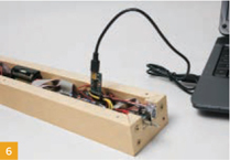
6c. Restart the Arduino IDE and open up the code file PS2You.pde. Connect your computer to the Ardweeny with the FTDI programming adapter. Click Verify and Upload, and if all is well, a moment later the display will light up with the default text.
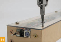
6d. Unplug the programmer, load some batteries into the battery packs (if you’re going to be using battery power), and screw on the back cover. You’re all set!
USE IT.

MAKE SOME BRIGHT REMARKS
Input and Output Modes
The PS/2/You has an Input mode for entering text and an Output mode for displaying it. Pressing any alphanumeric key puts the system into Input mode, and hitting Enter gets you back to Output mode.
In Input mode, the PS/2/You displays a single line of text as you type it in, a maximum of 100 characters long. You can store up to 6 lines of text (this number is settable by changing the value of numLines near the beginning of PS2You.pde). Use the up and down arrow keys to select which line to edit, and backspace over any line of text or hit Escape to delete it.
In Output mode, the display loops through the stored text lines on its own, displaying each for one second, or if the line is longer than 16 characters, it will scroll across the display before moving onto the next line. If only one line of text is stored, it displays continuously.
Text Messaging
The uses for this contraption are many. Plug the keyboard in and enjoy putting your wittiest “wiseclacks” on it in the safety of your home, shop, or office — or use the battery option to take it into the wide world. We like to have the keyboard accessible so that passersby can add a riposte or two to the dialogue. But if monologue is more your thing, you can always keep the keyboard out of reach.
Add a dowel as a removable handle so you can wander the streets digitally promoting your geekified political leanings. Keep score (or heckle) at sporting events, deliver birthday greetings, advertise your wares at a farmer’s market, beam cryptic messages to your neighbors — the possibilities are endless!

Further Illuminations
There’s plenty of room for improvement to the code. Try using Ctrl and other keys to modify how the text displays: flashing, sliding in from the top, fading in, or other effects.
Four display panels can be cascaded together for a longer display, and Sure Electronics sells an identically programmable 8×32 panel with 5mm instead of 3mm LEDs, so a jumbo PS/2/You is almost inevitable.
Roll Your Own Glyphs
The display font is defined by hexadecimal values in the font.h file. It’s not user-friendly for editing, but Brent Morse has made a free applet that lets you design your own 5×7 LED display glyphs (morse-code.com/id89.htm). Use it to modify the font, or make custom smilies or any other pattern you like. ![]()
![]() Visit makeprojects.com/v/27 for the PS/2/You circuit schematic, code, and more.
Visit makeprojects.com/v/27 for the PS/2/You circuit schematic, code, and more.