
TELECLAW:
REMOTE ROBOT
GRIPPER 
It might have been Robots of Saturn that first got my young brain thinking about building a mechanical man. In that obscure 1962 sci-fi adventure novel, Dig Allen and his fellow teenage space explorers transfer their thoughts into the bodies of teleoperated robots to mine Saturn’s dangerous rings for precious Methane-X.
Using some of my stepfather’s “extra” ham radio gear, I tried to build my own telerobot, with plans of world domination swimming through my head. I didn’t get far, but now, with powerful yet inexpensive microcontrollers, maybe this time it’ll work.
Big ideas begin with small steps, so let’s start petite, cheap, and easy. Here’s how to build a super-affordable remote robotic gripper that can pay the pizza delivery guy.
The telerobotic gripper (let’s call it the Teleclaw) has three main parts (Figure A). The mechanics include a $2 plastic clamp, a radio-controlled (R/C) servomotor, some stiff wire, and a bracket to hold it all together. The electronics are a simple circuit designed around the Picaxe 08M microcontroller and an infrared (IR) receiver/demodulator module.
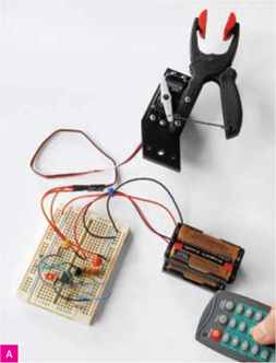
The remote control unit is an ordinary TV/VCR/DVD remote. You can use a remote you already have or get a cheap one just for this project. I paid 99 cents for the model here, but note that cheaper remotes usually have shorter ranges.

START
1. Construct the gripper mechanics.
If you’re making your own gripper bracket, use rigid ¼" plywood or expanded PVC, and follow the diagram in Figure B. For a quick prototype you can use ¼" foam board.
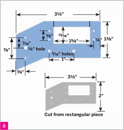
Saw out the bracket’s basic shape, then drill the mounting holes, all 1/8" unless otherwise noted. For the rectangular cutout (which will fit the servo), you can drill a starter hole and thread a thin saw blade through to cut out the rest, or else just cut through along the dotted lines shown in the diagram.
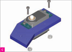
Secure the servo into the bracket using four 4-40×½" machine screws and nuts, with the shaft end near the bracket’s bend (Figure C).
Drill 2 (or possibly 3) 1/8" holes through the clamp handles, one at the end of one grip (my clamp already had this) and 2 more 1" apart along the other, matching the 3/16" holes in the bracket (Figure D, page 64).

Gordon McComb
Use flush cutters to trim the plastic away from the clamp’s handle around the red ratcheting piece, then yank out the ratcheting mechanism with heavy-duty pliers.
USE A TV REMOTE TO GRAB AND RELEASE SMALL OBJECTS FROM AFAR.
MATERIALS
See makeprojects.com/v/27 for recommended suppliers, prices, and other sourcing information.
MAKE Telerobotic Gripper Kit item #MSTGK from the Maker Shed (makershed.com/teleclaw), includes all of the following project Materials:
Clamp, ratcheting plastic, about 5" long, with jaws that open at least 1¼" such as Sears Craftsman #31594
Servomotor, radio-controlled (R/C), standard size (roughly 40mm×20mm×38mm), with double-arm horn such as GWS S03N STD. Save your money and skip the fancy digital or metal gear servos.
Picaxe 08M microcontroller
Infrared remote control compatible with Sony equipment
Infrared receiver/demodulator, 38kHz Be sure it has a wide voltage range if using the Picaxe at less than 5V DC.
Gripper bracket ready-made or cut from aircraft-grade plywood or expanded rigid PVC, ¼" thick, 3½"×2"
Stiff wire unbent 2¼" coilless safety pin or a 3" length of 18 gauge or thicker steel or brass wire (not annealed)
Solderless breadboard, half-size Maker Shed #MKKN2
Hookup wire, solid core, 22 AWG Maker Shed #MKEL1
Stereo audio jack, 3.5mm
Resistors, ¼W, 2%–5% tolerance: 330Ω (2), 4.7kΩ, 10kΩ, 22kΩ
Capacitors, electrolytic, 15V or greater: 4.7μF, 47μF
LED, T1¾ (5mm) any color
Power supply, 5V DC, regulated, 200mA minimum or battery holder with 3×AAA alkaline batteries (4.5V) or 4×AAA NiCd or NiMH rechargeable batteries (4.8V); for Picaxe.
Power supply or wall adapter, 6V DC, 750mA minimum or battery holder with 4×AA batteries
Machine screws, 4-40 pan head: ½" (4), ¾" (2)
Nuts, 4-40 hex (6)
TOOLS
Picaxe USB programming cable, AXE027 If you use a different Picaxe cable, you’ll need a different connector than the 3.5mm stereo jack specified above.
Saw(s) to cut the bracket; e.g. hacksaw, jigsaw, scroll saw
Drill and drill bits: 1/8", 3/16", ¼" plus a bit to start the cutout for the servo (optional)
Wire cutters (flush cutter type) and wire strippers
Pliers: needlenose and lineman’s (heavy-duty)
Computer with internet connection
Soldering iron and solder
Multimeter (optional) to test connections
Mount the clamp to the bracket using two 4-40×¾" bolts and nuts. Make them tight without seriously deforming the plastic.
Drill a 1/8" hole toward the end of one side of a double-arm servo horn and temporarily fit the horn over the servo shaft. Slowly rotate the servo counterclockwise until the motor hits its internal stop, then back off about 5°. Reposition the horn so that its arms are in the 9 o’clock and 3 o’clock positions, then attach it to the servo using the included screw.
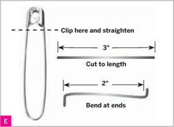
Clip off the clasp from a 2¼" coilless safety pin, straighten it, and cut a 3" length (or just start with 3" of stiff wire). Bend ½" of each end of the wire 90° in opposite directions to make a thin “S” hook (Figure E).
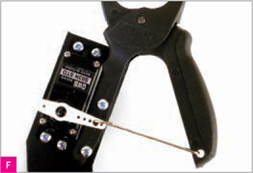
Hook the wire through the holes in the servo horn and the outside handle of the clamp. Use needlenose pliers to crimp the wire around the horn and handle loosely, so that it won’t bind (Figure F).
2. Build the gripper electronics.
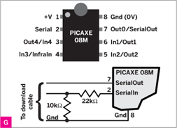
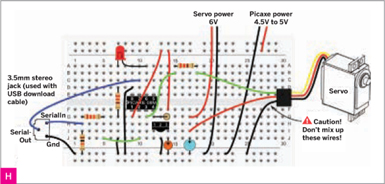
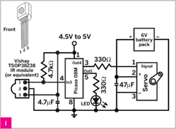
Following the schematics (Figures G and I), wire the circuit together on a solderless breadboard (you can transfer it to a soldered board later). Keep lead lengths short, especially for the 2 capacitors. Leave one side of each battery pack unconnected for now.
![]() WARNING:
WARNING:
Double- and triple-check the wiring before applying power, and make sure the power connections aren’t reversed, or else permanent damage can result to the Picaxe, the capacitors, and the servo. Reversing the voltage to the servo can cause its nearly instant (and sometimes explosive) death!
For simplicity, this project uses 2 separate voltages, one non-regulated, to operate the Picaxe and the servo. See makeprojects.com/v/27 for how to power the Teleclaw from a single 4.5V–5V supply.
Solder leads to the 3.5mm stereo jack, which the Picaxe programming cable will plug into. Connect the jack and 2 remaining resistors to your board as shown in Figures G and H. All resistors must remain in place even after you’ve uploaded your program.
3. Set up your remote.
If you’re using a universal remote, follow its instructions for how to set it up for a Sony TV, VCR, or DVD player. With my remote, for example, I selected VCR code 098. The Picaxe 08M has built-in commands for reading and decoding Sony SIRC protocol IR codes.
4. Program the Picaxe.
Download and install the free Picaxe Program Editor (Windows) or AXEpad (Mac/Linux) software from picaxe.co.uk. Plug your programming cable between your computer’s USB and the 3.5mm jack.
Launch the Program Editor or AXEpad, and specify 08M under Options → Target Device. Also select the serial port used with the download cable.
Download the project code from makeprojects.com/v/27 and open it in the editor. Apply power to the microcontroller circuit only — the servo doesn’t need to be powered yet — and click the Program button to compile and transfer the code to your Picaxe.
5. Now play!
Connect power to the servo, then disconnect and reconnect power to the Picaxe. The LED should glow to indicate when the Picaxe is sending pulses to the R/C servo, and the servo should quickly center itself.
Point the remote at the IR receiver on the breadboard and start pressing buttons to control the servo actions as follows:
» Channel Up/Channel Down — close/open the gripper incrementally.
» 2/8 — close/open the gripper fully.
» 5 — set the gripper to midway.
» 0 — toggle the servomotor power on and off (to extend battery life).
The gripper should be closed, or nearly so, when the servo is rotated all the way clockwise. To adjust its range, unscrew the servo horn from the servo’s motor shaft, reposition it, and put the screw back on.
The 0 button toggles “active” mode. Press it once (the LED goes out), and the servo shuts off after each move, saving power and eliminating a slight jitter. Press 0 again (the LED goes on), and the servo receives periodic pulses to set its position, which makes it maintain a tighter grip on things.
Comments in the code explain how to change parameters to fine-tune your Teleclaw.
That’s it! It’s just that simple. In the next installment of Telerobots for World Domination, I’ll tackle the job of creating a weapons system consisting of a pulsed atomic-powered rail gun and chemical laser. Stay tuned, fellow space explorers!
Gordon McComb, “the father of hobby robotics,” has been building robots since the 1970s, and wrote the bestselling Robot Builder’s Bonanza. Read his plans to take over the world with an army of mind-controlled automatons at robotoid.com.