
ELECTRONICS: FUN AND FUNDAMENTALS
The Do-Not-Touch Box
Use a simple accelerometer to perplex your friends.
ACCELEROMETERS HAVE BECOME
ubiquitous. Your car contains an accelerometer that triggers the deployment of an airbag if it senses a collision. The game controller on a Nintendo Wii contains an accelerometer that responds to your physical movements. If you build a robot, and you want it to react appropriately when it bumps into something or falls over, an accelerometer can take care of that, too.
Modern accelerometers are truly amazing, microscopic devices, packaged inside tiny integrated circuit chips that can cost less than 50 cents each. This kind of chip is known as a MEMS (micro-electro-mechanical system), and if you want to see how they work, you can find some fascinating electron micrographs by searching online for “mems device.”
I can imagine dozens of hobby projects using accelerometers. The only problem is that MEMS chips are so small, typically less than 5mm square, that they’re very difficult to work with. Fortunately you can buy one already mounted with associated hardware on a mini-board measuring ½"×¾", ready to be plugged into an everyday breadboard.
The price may seem high (the one I recommend currently retails for $23, which is among the cheapest) but in the project I have in mind, the additional parts should cost you less than $5.
Experimenting with the Accelerometer
I selected the DE-ACCM6G made by Dimension Engineering (Figure A). This is a 2-axis accelerometer, meaning that it will detect transitions in 2 perpendicular directions. Looking down at it from directly above, when you move it from left to right, this is considered motion along its x-axis, and the voltage at the lower-right pin will increase momentarily. Move it from right to left, and the voltage on the same pin will diminish momentarily (see Figure B).
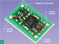
![]() Fig A: Closeup of the DE-ACCM6G accelerometer package, mounted on a mini-board measuring ½"×¾". Four pins (unseen, below the board) insert into a standard breadboard. Solder pads above each pin are labeled with the pin functions.
Fig A: Closeup of the DE-ACCM6G accelerometer package, mounted on a mini-board measuring ½"×¾". Four pins (unseen, below the board) insert into a standard breadboard. Solder pads above each pin are labeled with the pin functions.
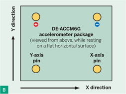
![]() Fig B: Functions of the output pins of the accelerometer when it’s moved in the directions shown.
Fig B: Functions of the output pins of the accelerometer when it’s moved in the directions shown.
When you push the accelerometer away from you, and then pull it back toward you, this is considered motion along the y-axis, creating voltage fluctuations on the lower-left pin.
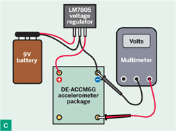
You can easily test this with just a 9V battery, an LM7805 voltage controller, and a multimeter, as shown in Figure C. The LM7805 supplies 5V, which you connect with the 2 top pins on the mini-board. But which end is the top end? You can compare it with the photographs here, or look underneath, and you should find the pins identified as X and Y (the outputs), Gnd (negative voltage), and Vin (positive voltage). Make sure you apply the voltage to the correct pair of pins, the right way around!
Charles Platt
![]() Fig C: Necessary connections to test the accelerometer. In reality it should be mounted with the voltage regulator on a breadboard, using jumper wires to make the connections shown.
Fig C: Necessary connections to test the accelerometer. In reality it should be mounted with the voltage regulator on a breadboard, using jumper wires to make the connections shown.
Set your meter to DC volts, using the 2V range if the meter doesn’t do auto-ranging. Hold the black probe in contact with the negative side of your power supply, and touch the red probe to each of the little solder pads above the output pins of the accelerometer. While the component is horizontal and motionless, your meter should show approximately 1.65V on each pin. Now slide the accelerometer around, and watch how the voltages change.
What happens if you lift the mini-board directly upward? Nothing! To detect motion in the third dimension, you would need a 3-axis accelerometer.
MATERIALS
DE-ACCM6G accelerometer available from trossenrobotics.com or robotshop.com
Resistor, ¼W or higher, 3.3kΩ
Piezoelectric beeper, steady-tone, drawing less than 20mA such as Kobitone 254-PB511-ROX or model 273-073 from RadioShack (radioshack.com)
Differential comparator such as TLC372IP, TLC372CP, or similar
LM7805 voltage regulator You can ignore any additional letters appended to this part identifier.
9V battery and snap connector
Breadboard and jumper wires
Try tilting the breadboard away from you until it’s vertical, resting on its top edge. After the Y output stabilizes, it should show about 1.88V, suggesting that the component is accelerating downward, even though it isn’t moving. How can this be?
Well, one of Einstein’s great insights was that gravity is indistinguishable from acceleration. You could be sitting in a rocket out in space, accelerating smoothly at 1 gravity (1g), or you could be sitting motionless in that same rocket on the launch pad, experiencing the gravitational pull of the Earth, and you would have no way to detect the difference. Strange but true: you and all the objects around you are experiencing a constant 1g downward acceleration right now.
Here’s another little experiment. Hold the accelerometer, the meter, and the battery on your knees while you spin around in an office chair. The accelerometer will measure your outward centripetal acceleration, which is often referred to (inaccurately) as centrifugal force. Acceleration is a fascinating concept, and your accelerometer can help you to explore it.
But how can we make practical use of the chip on its mini-board? The smart way is to connect it with a microcontroller such as the Arduino, BASIC Stamp, or Picaxe. All of these chips contain analog-to-decimal converters, allowing you to write a little program that tells the microcontroller what to do when it senses small changes in voltage. You can set up a numeric display showing acceleration in gravities (g), and mount it in a car, on a bicycle, or on your own body when you jump up and down on a trampoline.
But let’s start with something simpler. I’m going to use the accelerometer to make a Do Not Touch Box.
 START
START
Building the Box
I have to admit that if I see a little box with “do not touch” written on it, I can’t resist picking it up. This little project will deliver a harmless surprise to anyone who yields to that temptation.
In Figure D, the schematic shows that 2 outputs from the accelerometer can drive the 2 inputs of a chip called a comparator (part #TLC372). One of these inputs is known as the inverting input (usually marked with a minus sign) while the other is called the noninverting input (marked with a plus sign). The comparator constantly compares its inputs. If the inverting input has a higher voltage than the non-inverting input, the output from the comparator will be low, and vice versa.
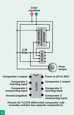
![]() Fig D: Schematic showing a TLC372 comparator attached to the accelerometer package, driving a beeper. Because the TLC372 output goes low when active, the beeper is connected to positive power, which it sinks into the comparator. The 3.3K resistor pulls the output of the TLC372 higher when it’s not sinking current.
Fig D: Schematic showing a TLC372 comparator attached to the accelerometer package, driving a beeper. Because the TLC372 output goes low when active, the beeper is connected to positive power, which it sinks into the comparator. The 3.3K resistor pulls the output of the TLC372 higher when it’s not sinking current.
Because the comparator has a very high input impedance, you can wire it directly to the accelerometer mini-board.
The comparator is an open-collector device, which means that you should use its output pin to sink current. (To learn more about this concept, consult an introductory book, such as my own Make: Electronics.) Therefore, you can think of the comparator as “switching on” when its output goes low. It can sink 20mA, which is easily enough to power a piezoelectric beeper.
Connect positive voltage to the red wire of the beeper, connect its black wire to the output from the comparator, and the beeper will beep when the comparator output goes low. However, you also need to use a pull-up resistor to insure that the comparator output is high when the comparator is inactive (Figure E).

![]() Fig E: This breadboard layout corresponds with the schematic in Figure D. Wires from a 9V battery are applied to the top 2 rows of the breadboard. The LM7805 voltage regulator, seen from above, is the black rectangle at top right. The TLC372 comparator pinouts are: pin 1, output; pin 2, inverting input; pin 3, non-inverting input; pin 4, negative power; pin 8, positive power; pins 5, 6, and 7 connect with a second, separate comparator inside the chip, and can be left with no connection.
Fig E: This breadboard layout corresponds with the schematic in Figure D. Wires from a 9V battery are applied to the top 2 rows of the breadboard. The LM7805 voltage regulator, seen from above, is the black rectangle at top right. The TLC372 comparator pinouts are: pin 1, output; pin 2, inverting input; pin 3, non-inverting input; pin 4, negative power; pin 8, positive power; pins 5, 6, and 7 connect with a second, separate comparator inside the chip, and can be left with no connection.

The beeper may not beep when you first apply power to the circuit. Gently tilt your breadboard in each direction, and whenever the x-axis output is greater than the y-axis output, the comparator will activate the beeper.
Inside a suitable box, mount the components at a slight angle, so that the beeper will remain silent while the box is resting on a level surface. Label the box, leave it in an obvious place, and wait for someone to take the bait. As soon as the box is disturbed, it will start beeping, and the person holding it will have a hard time figuring out what makes it beep and what keeps it quiet.
Because the electronics consume only about 5mA while they’re waiting for something to happen, the 9V battery should last for 2 or 3 days of continuous use.
Going Further
If this little project rouses your curiosity, here are some more ideas:
» Search online for comparator hysteresis to learn how a comparator can tolerate larger differences between inputs before emitting a signal. Hysteresis is an important concept when sensing changes in the environment.
» Connect the x-axis output from the accelerometer to one input of the comparator. Using a voltage divider, apply a fixed, constant 1.65V to the other input. Use hysteresis so that the comparator isn’t triggered unless the voltages on its inputs differ significantly. Now the comparator only senses acceleration or tilting along the x-axis.
» The TLC372 chip actually contains 2 comparators. You can use the second one to sense changes in the y-axis. Now you have the beginnings of an attitude control system in some kind of flying or walking device.
» You can wire the comparator so that it only responds to large fluctuations. In this mode, it will detect impacts or collisions. You’ll find a circuit that does this on the Trossen Robotics website, which sells the DE-ACCM6G comparator (see the Materials list).
» Try using a 555 timer to generate an audible tone, and feed an output from the accelerometer to pin 5 (the Control pin) of the timer. When you hold the accelerometer while making hand motions, the tone will change pitch. (You may need an op-amp to increase the accelerometer voltage output for the 555 input.)
I’m sure you can come up with many more fun accelerometer projects of your own. ![]()
![]() Make: Electronics book at the Maker Shed: makezine.com/go/makeelectronics
Make: Electronics book at the Maker Shed: makezine.com/go/makeelectronics
Charles Platt is the author of Make: Electronics, an introductory guide for all ages. A contributing editor of MAKE, he designs and builds medical equipment prototypes in Arizona.