
AutoCAD drawings contain a wealth of data—graphic information such as distances and angles between objects as well as precise areas and the properties of objects. However, as you become more experienced with AutoCAD, you'll also need data of a different nature. For example, as you begin to work in groups, the various settings in a drawing become important. You'll need statistics on the amount of time you spend on a drawing when you're billing computer time. As your projects become more complex, file maintenance requires a greater degree of attention. To take full advantage of AutoCAD, you'll want to exchange information about your drawing with other people and other programs.
In this chapter, you'll explore the ways in which all types of data can be extracted from AutoCAD and made available to you, your coworkers, and other programs. First you'll learn how to obtain specific data about your drawings. Then you'll look at ways to exchange data with other programs—such as word processors, desktop-publishing software, and even other CAD programs.
In this chapter, you'll learn to do the following:
Find the area of closed boundaries
Get general information
Use the DXF file format to exchange CAD data with other programs
Use AutoCAD drawings in page-layout programs
Use OLE to import data
One of the most frequently sought pieces of data you can extract from an AutoCAD drawing is the area of a closed boundary. In architecture, you want to find the area of a room or the footprint of a building. In civil engineering, you want to determine the area covered by the boundary of a property line or the area of cut for a roadway. In the following sections, you'll learn how to use AutoCAD to obtain exact area information from your drawings.
Architects, engineers, and facilities planners often need to know the square footage of a room or a section of a building. A structural engineer might want to find the cross-sectional area of a beam. In this section, you'll practice determining the areas of regular objects.
First you'll determine the square-foot area of the living room and entry of your studio unit plan:
Start AutoCAD. Open the
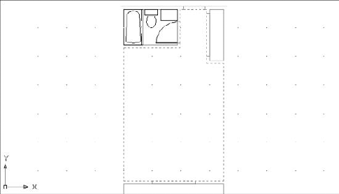
Unitfile you created earlier, or use the20a-unit.dwgfile.Zoom in to the living room and entry area so you have a view similar to Figure 20.1.

Using the Endpoint osnap, start with the lower-left corner of the living room and select the points shown in Figure 20.1. You're indicating the boundary. Notice that as you click points, the area being calculated is indicated in green.
When you've come full circle to the eighth point shown in Figure 20.1, press

Area = 39570.00 square in. (274.7917 square ft), Perimeter = 76'-0"
Type X

The number of points you can pick to define an area is limitless, so you can obtain the areas of complex shapes. Use the Blipmode feature to keep track of the points you select so you know when you come to the beginning of the point selections.
Find the Coordinate of a Point or a Distance in a Drawing
To find absolute coordinates in a drawing, use the ID command. Click the ID Point tool on the Home tab's expanded Utilities panel, or type ID
To find the distance between two points, choose Distance from the Measure flyout on the Home tab's Utilities panel, or type Dist
Hatch patterns are used primarily to add graphics to your drawing, but they can also serve as a means to finding areas. You can use any hatch pattern you want because you're interested in only the area it reports back to you. You can also set up a special layer devoted to area calculations and then add the hatch patterns you use to find areas to this layer. That way, you can turn off the hatch patterns so they don't plot, or you can turn off the Plot setting for that layer to ensure that it doesn't appear in your final output.
To practice using hatch patterns to find an area, do the following:
Set the current layer to Floor.
Turn off the Door and Fixture layers. Also make sure the Ceiling layer is turned on. You want the hatch pattern to follow the interior wall outline, so you need to turn off any objects that will affect the outline, such as the door and kitchen.


At the
Pick internal point or [Select objects/remove Boundaries]:prompt, click in the interior of the Unit plan. The outline of the interior is highlighted (see Figure 20.2).Press

Click the hatch pattern you just created. Again, you get the following message:
Area = 39570.00 square in. (274.7917 square ft), Perimeter = 76'-0"
Press X
If you need to recall the last area calculation value you received, enter ′Setvar
The Hatch command creates a hatch pattern that conforms to the boundary of an area. This feature, combined with the ability of the Measuregeom command to find the area of a hatch pattern, makes short work of area calculations. Another advantage of using hatch patterns is that, by default, hatch patterns avoid islands within the boundary of the area you're trying to find.
The area of a hatch pattern is also reported by the Properties palette. Select the hatch pattern whose area you want to find, and then right-click and select Properties. Scroll down to the bottom of the Geometry group, and you'll see the Area listing for the hatch pattern you selected. You can select more than one hatch pattern and find the cumulative area of the selected hatch patterns in the Properties palette.
Hatch patterns work extremely well for finding areas, but if you find that for some reason you can't use hatch patterns, you have another alternative. You can still use a command called Boundary to generate a polyline outline of an enclosed boundary and then obtain the area of the outline using the Measuregeom command (Measure on the Home tab's Utilities panel). If islands are present within the boundary, you have to use the Subtract feature of the Measuregeom command to remove the area of the island from the overall boundary area. In this section, you'll use the example of the flange part, which contains two islands in the form of the two circles at the lower end (see Figure 20.3).

By using the Add and Subtract options of the Measuregeom command, you can maintain a running total of several separate areas being calculated. This gives you flexibility in finding areas of complex shapes. This section guides you through the use of these options.
For the following exercise, you'll use a flange shape that contains circles. This shape is composed of simple arcs, lines, and circles. Use these steps to see how you can keep a running tally of areas:
Exit the
Unitfile, and open the fileFlange.dwg(see Figure 20.3). Don't bother to save changes in theUnitfile.
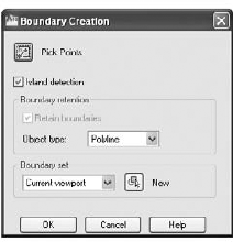
Click Pick Points.
Click in the interior of the flange shape. The entire shape is highlighted, including the circle islands.

Continue by using the Measuregeom command's Add and Subtract options. Click Area from the Measure flyout on the Home tab's Utilities panel.
Type A
Click a vertical edge of the flange outline. You see the selected area highlighted in green, and the following message appears in the Command window:
Area = 27.7080, Perimeter = 30.8496
Total area = 27.7080
Press
Type S
Click one of the circles. You see the following message:
Area = 0.6070, Perimeter = 2.7618
Total area = 27.1010
This shows you the area and perimeter of the selected object and a running count of the total area of the flange outline minus the circle. You also see the area of the subtracted circle change to a different color so you can differentiate between the calculated area and the subtracted area.
Click the other circle. You see the following message:
Area = 0.6070, Perimeter = 2.7618
Total area = 26.4940
Again, you see a listing of the area and perimeter of the selected object along with a running count of the total area, which now shows a value of 26.4940. This last value is the true area of the flange.
Press
In this exercise, you first selected the main object outline and then subtracted the island objects. You don't have to follow this order; you can start by subtracting areas to get negative area values and then add other areas to come up with a total. You can also alternate between Add and Subtract modes, in case you forget to add or subtract areas.
You may have noticed that the Measuregeom Command prompt offered Specify first corner point or [Object/Add/Subtract/eXit]: as the default option for both Add and Subtract modes. Instead of using the Object option to pick the circles, you can start selecting points to indicate a rectangular area, as you did in the first exercise in this chapter.
Whenever you press
As you can see from these exercises, it's simpler to outline an area first with a polyline wherever possible and then use the Object option to add and subtract area values of polylines.
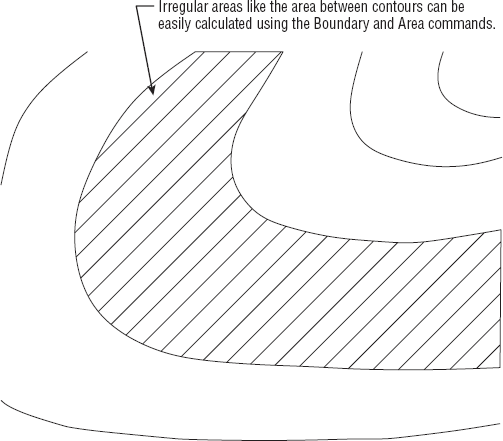
In this example, you obtained the area of a mechanical object. However, the same process works for any type of area you want to calculate. It can be the area of a piece of property on a topographical map or the area of a floor plan. For example, you can use the Object option to find an irregular shape such as the one shown in Figure 20.5, as long as it's a polyline.
The Measuregeom command offers a number of other options for measuring your drawing. The options appear in the Command window as [Distance/Radius/Angle/ARea/Volume/eXit] or at the cursor as a Dynamic Input option. These options are automatically selected when you click the related tool from the Measure flyout on the Utilities panel. Remember that to use an option, type the capitalized letter or letters of the option shown in the list. Table 20.1 gives you descriptions of the options and how they are used.
Table 20.1. The Measuregeom Command Options
So far in this book, you've seen how to get data about the geometry of your drawings. AutoCAD also includes a set of tools that you can use to access the general state of your drawings. You can gather information about the status of current settings in a file or the time at which a drawing was created and last edited.
In the following sections, you'll practice extracting this type of information from your drawing, using the tools found in the Tools tab's Inquiry panel.
When you work with a group of people on a large project, keeping track of a drawing's setup becomes crucial. You can use the Status command to obtain general information about the drawing you're working on, such as the base point, current mode settings, and workspace or computer memory use. The Status command is especially helpful when you're editing a drawing someone else has worked on because you may want to identify and change settings for your own style of working. Click Drawing Utilities

Here is a brief description of each item on the Status screen. Note that some of the items you see on the screen will vary somewhat from what I've shown here, but the information applies to virtually all situations except where noted:
- Number Objects In Drive:FolderSubfolderName.dwg
- Model Space Limits Are
The coordinates of the Model Space limits. Also indicates whether limits are turned off or on. (See Chapter 3 for more details on limits.)
- Model Space Uses
The area the drawing occupies; equivalent to the extents of the drawing.
- **Over
If present, means that part of the drawing is outside the limit boundary.
- Display Shows
The area covered by the current view.
- Insertion Base Is, Snap Resolution Is, and Grid Spacing Is
The current default values for these mode settings.
- Current Space
Model Space or Paper Space.
- Current Layout
The current tab.
- Current Layer
The current layer.
- Current Color
The color assigned to new objects.
- Current Linetype
The linetype assigned to new objects.
- Current Material
The material assigned to new objects.
- Current Lineweight
The current default lineweight setting.
- Current Elevation/Thickness
The current default Z coordinate for new objects, plus the default thickness of objects. These are both 3D-related settings. (See Chapter 21 for details.)
- Fill, Grid, Ortho, Qtext, Snap, and Tablet
- Object Snap Modes
The current active Osnap setting.
- Free Dwg Disk (Drive:)Space
The amount of space available to store drawing-specific temporary files.
- Free Temp Disk (Drive:) Space
The amount of space left on your hard drive for AutoCAD's resource temporary files.
- Free Physical Memory
The amount of free RAM available.
- Free Swap File Space
The amount of Windows swap-file space available.
When you're in Paper Space, the Status command displays information regarding the Paper Space limits. See Chapter 16 for more on Model Space and Paper Space.
In addition to being useful in understanding a drawing file, the Status command is an invaluable tool for troubleshooting. Frequently, a technical support person can isolate problems by using the information provided by the Status command.
The Time command enables you to keep track of the time spent on a drawing for billing or analysis purposes. You can also use the Time command to check the current time and find out when the drawing was created and most recently edited. Because the AutoCAD timer uses your computer's time, be sure the time is set correctly in Windows.
To access the Time command, enter Time
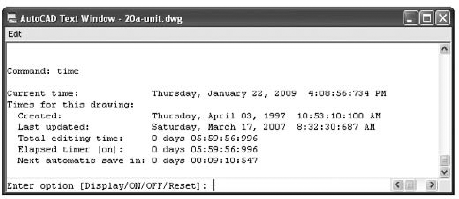
The first four lines of this message tell you the current date and time, the date and time the drawing was created, and the last time the drawing was saved.
The fifth line shows the total time spent on the drawing from the point at which the file was opened. This elapsed timer lets you time a particular activity, such as changing the width of all the walls in a floor plan or redesigning a piece of machinery. The last line tells you when the next automatic save will be.
You can turn the elapsed timer on or off or reset it by entering ON, OFF, or Reset at the prompt shown at the bottom of the message. Or press
If you've been working through this book's ongoing studio apartment building tutorial, you'll have noticed that I've occasionally mentioned a system variable in conjunction with a command. You can check the status or change the setting of any system variable while you're in the middle of another command. To do this, you type an apostrophe (′) followed by the name of the system variable at the Command prompt.
For example, if you start to draw a line and suddenly decide you need to rotate your cursor 45°, you can do the following:
At the
Specify next point or [Undo]:prompt, enter ′snapang.At the
Enter new value for SNAPANG <0>:prompt, enter a new cursor angle. You're returned to the Line command with the cursor in its new orientation.
You can also recall information such as the last area or distance calculated by AutoCAD. Type Setvar
Many system variables give you direct access to detailed information about your drawing. They also let you fine-tune your drawing and editing activities. In Appendix D, you'll find all the information you need to familiarize yourself with the system variables. Don't feel that you have to memorize them all at once; just be aware that they're available.
At times, you may find it helpful to keep a log of your activity in an AutoCAD session. A log is a text file containing a record of your activities. It can also contain notes to yourself or others about how a drawing is set up. Such a log can help you determine how frequently you use a particular command, or it can help you construct a macro for a commonly used sequence of commands.
The following exercise demonstrates how to save and view a detailed record of an AutoCAD session by using the Log feature:
Choose Options from the Application menu to open the Options dialog box. Click the Open And Save tab. A new set of options appears.
In the File Safety Precautions group, click the Maintain A Log File check box and then click OK.
Type Status
Return to the Open And Save tab of the Options dialog box, and turn off the Maintain A Log File option.
Click OK to exit the dialog box.
Switch to Windows, and start the Notepad application or any text editor.
With the text editor, open the log file whose name starts with
Flangein the folder listed here:C:Documents and SettingsUser NameLocal SettingsApplication DataAutodeskAutoCAD 2010R18.0enuThis file stores the text data from the Command prompt whenever the Log File option is turned on. You must turn off the Log File option before you can view this file. When you're attempting to view the log file using Windows Notepad, make sure you set File Of Type in the Notepad Open dialog box to All Files.
As a shortcut, you can quickly turn the Maintain A Log File feature on and off by typing Logfileon
If you're working in groups, it's often helpful to have a record of the status, editing time, and system variables for particular files readily available to other group members. It's also convenient to keep records of block and layer information so you can see whether a specific block is included in a drawing or what layers are normally on or off.
You can use the Windows Clipboard to capture and save such data from the AutoCAD Text Window. The following steps show you how it's done:
Move the arrow cursor to the Command prompt at the bottom of the AutoCAD Text Window.
Right-click and choose Copy History from the shortcut menu to copy the contents of the AutoCAD Text Window to the Clipboard.
If you want to copy only a portion of the AutoCAD Text Window to the Clipboard, perform the following steps:
Press the F2 function key to open the AutoCAD Text Window.
Using the I-beam text cursor, highlight the text you want to copy to the Clipboard.
Right-click and choose Copy from the shortcut menu. Or you can type Ctrl+C. The highlighted text is copied to the Clipboard.
Open Notepad or another text-editing application, and paste the information.
Although you used the AutoCAD Text Window to copy text in this exercise, you can also copy from the docked command line at the bottom of the AutoCAD window.
You may notice four other options on the shortcut menu: Recent Commands, Paste, Paste To CmdLine, and Options. Choosing Recent Commands displays a list of the most recent commands. For most activities, you'll use a handful of commands repeatedly; the Recent Commands option can save you time by giving you a shortcut to those commands you use the most. The Paste options paste the first line of the contents of the Clipboard into the command line or input box of a dialog box. This can be useful for entering repetitive text or for storing and retrieving a frequently used command. Choosing Options opens the Options dialog box.
Items copied to the Clipboard from the AutoCAD Text Window can be pasted into dialog box input boxes. This can be a quick way to transfer layers, linetypes, or other named items from the AutoCAD Text Window into dialog boxes. You can even paste text into the drawing area.
As you start to build a library of AutoCAD files, you'll have to start thinking about how to manage them. Keeping track of AutoCAD files can be a daunting task. Most AutoCAD users start to name files by their job number to keep things organized. But even the best organization schemes don't help if you need to find that one special file among thousands of files in your library. In this section, you'll learn how to include information in an AutoCAD file that you can use later to locate the file by using the Windows Search utility.
AutoCAD includes the DesignCenter, a tool that can help you locate a file more easily based on a keyword or description. Chapter 29 contains a complete discussion of the DesignCenter.
Here are descriptions of the four tabs in this dialog box:
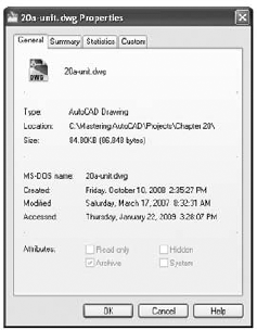
- General
The General tab gives you general information about the file. This information is similar to what you see if you use the Properties options in Windows Explorer to view the properties of a file.
- Summary
In the Summary tab, enter any text in the Title, Subject, Author, and Keywords fields that is appropriate to the drawing. The information you enter here is stored with the drawing and can be used to locate the file through the AutoCAD DesignCenter or the Windows Search utility.
In addition, you can enter a base location for hyperlinks that are applied to objects in your drawing. This base location can be a folder on your computer or network or an Internet web address. See Chapter 29 for more information on hyperlinks.
- Statistics
The Statistics tab contains the Windows username of the person who last saved the drawing as well as the time spent on the file. The username is the name used to log in at the beginning of the Windows session.
- Custom
The Custom tab contains two columns of input boxes. This tab lets you store with the drawing additional custom data that is also searchable. For example, you might enter Job Number in the Name column and then enter 9901 in the Value column. You might also include information such as project manager names, consultants, or revision numbers. You can then locate the file by using the AutoCAD DesignCenter or the Windows Search utility and doing a search for those keywords from the Name and Value columns.
After you've included information in a file's Properties dialog box, you can use the AutoCAD DesignCenter, the File dialog box, or the Windows Search function to locate your file.

This option opens a Find dialog box that works just like the Windows XP Search Results window.
No system is perfect. Eventually, you'll encounter a file that is corrupted in some way. Two AutoCAD tools can frequently salvage a corrupted file:
- Audit
Enables you to check a file that you can open but suspect has some problem. Audit checks the currently opened file for errors and displays the results in the AutoCAD Text Window.
- Recover
Enables you to open a file that is so badly corrupted that AutoCAD is unable to open it in a normal way. A Select File dialog box appears in which you select a file for recovery. After you select a file, it's opened and checked for errors.
You can access these tools from the Drawing Utilities option on the Application menu. More often than not, these tools will do the job, although they aren't a panacea for all file-corruption problems. In the event that you can't recover a file even with these tools, make sure your computer is running smoothly and that other systems aren't faulty.
If for some reason your computer shuts down while you're in the middle of editing a file, you'll see the Drawing Recovery Manager the next time you start AutoCAD. The Drawing Recovery Manager lets you recover the file you were working on when AutoCAD unexpectedly shut down. This feature works just like the file-recovery feature in Microsoft Office: A panel appears to the left of the AutoCAD Text Window showing you a list of recoverable files. You can then select the filename from the panel to open the file. You can find the Drawing Recovery Manager in the Application menu under Drawing Utilities
AutoCAD offers many ways to share data with other programs. Perhaps the most common type of data exchange is to share drawing data with other CAD programs. In the following sections, you'll see how to export and import CAD drawings using the DXF file format.
A Drawing Exchange Format (DXF) file is a plain-text file that contains all the information needed to reconstruct a drawing. It's often used to exchange drawings created with other programs. Many CAD and technical drawing programs, including some 3D perspective programs, can generate or read files in DXF format. You might want to use a 3D program to view your drawing in a perspective view, or you might have a consultant who uses a different CAD program that accepts DXF files.
Be aware that not all programs that read DXF files accept all the data stored therein. Many programs that claim to read DXF files throw away much of the DXF files' information. Attributes are perhaps the most commonly ignored objects, followed by many of the 3D objects, such as meshes and 3D faces.
To export your current drawing as a DXF file, follow these steps:
Choose Save As from the Application menu to open the Save Drawing As dialog box.
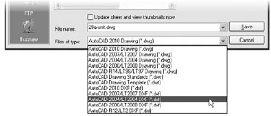
Click the Files Of Type drop-down list. You can export your drawing under a number of formats, including five DXF formats.
Select the appropriate DXF format, and then enter a name for your file. You don't have to include the
.dxffilename extension.Select a folder for the file and click Save.
In step 3, you can select from the following DXF file formats:
AutoCAD 2010 DXF
AutoCAD 2007 DXF (AutoCAD 2007, 2008, and 2009 share file formats)
AutoCAD 2004/LT 2004 DXF
AutoCAD 2000/LT 2000 DXF
AutoCAD R12/LT2 DXF
Choose the format appropriate to the program you're exporting to. In most cases, the safest choice is AutoCAD R12/LT2 DXF if you're exporting to another CAD program, although AutoCAD won't maintain the complete functionality of AutoCAD 2009 for such files.
After you've selected a DXF format from the Files Of Type drop-down list, you can set more detailed specifications by choosing Tools
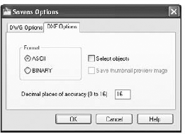
The DXF Options tab contains the following options:
- Format
Lets you choose between ASCII (plain-text) and binary file formats. Most other programs accept ASCII, so it's the safest choice. Some programs accept binary DXF files, which have the advantage of being more compact than the ASCII format files.
- Select Objects
Lets you select specific objects in the drawing for export. You can select objects after you close the Saveas Options dialog box and choose Save from the Save Drawing As dialog box.
- Decimal Places Of Accuracy (0 To 16)
Enables you to determine the accuracy of the exported file. Keeping this value low helps reduce the size of the exported file, particularly if it's to be in ASCII format. Some CAD programs don't support AutoCAD's high accuracy, so using a high value here may have no significance.
In addition to using the Save Drawing As dialog box, you can type Dxfout
Some offices have made the DXF file format their standard for CAD drawings. This is most commonly seen in offices that use a variety of CAD software besides AutoCAD.
AutoCAD can be set up to read and write DXF files instead of the standard DWG file format by default. Here's how it's done:
Choose Options from the Application menu to open the Options dialog box.
Select the Open And Save tab.
In the File Save group, select any of the DXF formats from the Save As drop-down list.
Click OK.
After you do this, all your drawings are automatically saved in the DXF format of your choice.
You can also set the default AutoCAD file type by clicking the Options button in the Save Drawing As dialog box. As you saw in the preceding section, the Saveas Options dialog box includes the DWG Options tab (Figure 20.10). You can select a default file type from the Save All Drawings As drop-down list.

If you need to open a DXF file only once in a while, you can do so by selecting DXF from the Files Of Type drop-down list in the Select File dialog box. This is the dialog box you see when you click Open from the Quick Access toolbar. You can also use the Dxfin command:
Type Dxfin
Locate and select the DXF file you want to import.
Double-click the filename. If the drawing is large, the imported file may take several minutes to open.
As you probably know, AutoCAD is a natural for creating line art, and because of its popularity, most page-layout programs are designed to import AutoCAD drawings in one form or another. Those of you who employ page-layout software to generate user manuals or other technical documents will probably want to use AutoCAD drawings in your work. In this section, you'll examine ways to output AutoCAD drawings to formats that most page-layout programs can accept.
You can export AutoCAD files to page-layout software formats in two ways: by using raster export and by using vector file export.
In some cases, you may need only a rough image of your AutoCAD drawing. You can export your drawing as a raster file that can be read in virtually any page-layout and word-processing program. To do this, you need to use the PublishToWebJPG.pc3 or PublishToWebPNG.pc3 printer option that comes with AutoCAD. To use it, do the following.
Click the Plot tool in the Quick Access toolbar.
In the Printer/Plotter group of the Plot dialog box, select PublishToWebJPG.pc3 or PublishToWebPNG.pc3 from the Name drop-down list.
The first time you use this printer option, you'll see the Plot – Paper Size Not Found dialog box. Select from the options presented in the dialog box.
Back in the Plot dialog box, you can select a size in pixels for your image file from the Paper Size drop-down list.
Click OK to create the image file.
In the Browse For Plot File dialog box, select a location for your file and click Save.
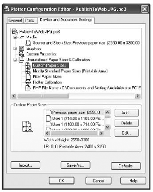
If you don't see a "paper size" you want to use, you can create a custom size using the Properties button in the Plot dialog box:
Follow the steps in the previous exercise, but at step 5, instead of clicking OK, click the Properties button to the right of the Printer/Plotter group's Name drop-down list. The Plotter Configuration Editor dialog box appears (see Figure 20.11).
Click Custom Paper Sizes in the large list box at the top of the dialog box. The options change in the lower half of the dialog box.
Click the Start From Scratch radio button, and then click Next to open the Media Bounds screen.
Enter a height and width in pixels for your image file, and then click Next to open the Paper Size Name screen. Enter a name that best describes the size of the image file, and click Next to open the File Name screen.
Enter a name for the Plotter Model Parameters file. This file stores specific setting information about the plotter. Click Next when you're finished.
On the Finish screen, click Finish. The Plotter Configuration Editor dialog box reappears. Click OK, and then click Finish in the Add-A-Plotter Wizard.
You can edit these settings at any time by opening the PC3 file in the Application DataAutodeskAutoCAD 2010R18.0enuPlotters subfolder of your profile folder. You can access this file through Windows Explorer or from AutoCAD by clicking Plotter Manager from the Output tab's Plot panel.
To create a raster file version of your drawing, click Plot from the Quick Access toolbar. Then, in the Plot dialog box, select your raster file plotter configuration from the Name drop-down list of the Printer/Plotter group. You can then proceed to plot your drawing, but instead of paper output, you'll get a raster file. You can specify the filename and location when you click the OK button to plot the file.
If you need to make changes to your raster file configuration, click Plotter Manager from the Output tab's Plot panel. Then, in the Plotters window, double-click your raster file configuration file. You'll see the same Plotter Configuration Editor you used to set up the raster plotter configuration.
You can set up a different plotter configuration for each type of raster file you use. You can also set up plotter configurations for different resolutions if you choose. To learn more about plotting in general, see Chapter 8. Appendix C provides detailed information on the Plotter Configuration Editor.
If you need to preserve the accuracy of your drawing, or if you want to take advantage of TrueType or PostScript fonts, you can use the DXF, Windows Metafile (WMF), or PostScript vector format. You can also export to DGN and SAT file formats. Intergraph's DGN format is popular in civil engineering, mapping, and other CAD applications. The SAT format is associated with ACIS and is a 3D modeling format.
For vector-format files, DXF is the easiest to work with, and with TrueType support, DXF can preserve font information between AutoCAD and page-layout programs that support the DXF format. The WMF format is also a commonly accepted file format for vector information, and it preserves TrueType fonts and lineweights used in your drawings.
PostScript is a raster/vector hybrid file format that AutoCAD supports. Unfortunately, AutoCAD dropped direct PostScript font support with Release 14. However, you can still use substitute fonts to stand in for PostScript fonts. These substitute fonts are converted to true PostScript fonts when AutoCAD exports the drawing. You don't see the true results of your PostScript output until you print your drawing on a PostScript printer.
The DXF file export was covered in a previous section of this chapter, so the following sections will concentrate on the WMF and PostScript file formats.
The WMF file type is one of the more popular vector file formats in Windows. It can be opened and edited by most illustration programs, including CorelDRAW and Adobe Illustrator. Most word-processing, database, and worksheet programs can also import WMF files. It's a great option for AutoCAD file export because it preserves TrueType fonts and lineweight settings. You can export WMF files that preserve lineweights as well.
To export WMF files, do the following:
Click Export

Enter a name and location for your WMF file, select Metafile (*.wmf) from the File Of Type drop-down list, and then click OK. The dialog box closes, and you're prompted to select objects.
Select the objects you want to export to the WMF file, and press
AutoCAD can export to the Encapsulated PostScript (EPS) file format. If you're using AutoCAD 2010, you can obtain PostScript output in two ways: You can choose Export
To set up AutoCAD to plot your drawing to an EPS file, follow these steps:
Choose Print
Choose Next on the Introduction screen.
On the Begin screen of the Add-A-Plotter Wizard, choose My Computer.
On the Plotter Model screen, select Adobe from the Manufacturers list, and then select the appropriate PostScript level from the Models list.
Skip the Import PCP Or PC2 screen and the Ports screen.
Enter a name for your EPS output settings on the Plotter Name screen.
On the Finish screen, click the Finish button.
AutoCAD doesn't preserve font information when creating EPS files from the printer option. It also produces larger files, especially if your drawing contains a lot of area fills and filled fonts. As an alternative to EPS, you can "plot" to an Adobe PDF file. EPS files can often be substituted with PDF files. You'll need to install the Autodesk-provided PDF plotter driver using the Add-A-Plotter Wizard described earlier. When you get to the Plotter Model screen, select the Autodesk ePlot (PDF) option from the Manufacturers list. You can also use the full version of Adobe Acrobat or Acrobat Pro to produce PDF files from AutoCAD.
The HPGL plot-file format is another vector format you can use to export your AutoCAD drawings. Use the method described earlier in the section "Exporting Raster Files" to add the HPGL plotter driver to your printer/plotter configuration.
To import data from other applications, you use the Cut and Paste features found in virtually all Windows programs. You cut the data from the source document and then paste it into AutoCAD. Typically, you'll want to paste data into AutoCAD in AutoCAD's native object format, but if you prefer, you can use a Windows feature called Object Linking and Embedding (OLE) to import files.
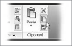
Finding the Copy and Paste Tools
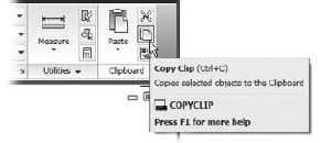
There are several variations of the Copy and Paste tools in AutoCAD, so they have been combined into tools and flyouts on the Home tab's Clipboard panel. The Paste flyout is in the large icon to the left and the Copy tool is the middle icon on the right.
When you paste data into your AutoCAD file using OLE, you can link it to the source file or you can embed it. If you link it to the source file, the pasted data is updated whenever the source file is modified. This is similar to an AutoCAD cross-referenced file. (See Chapter 15 for more on cross-referenced files.) If you embed data, you're pasting it into AutoCAD without linking it. You can still open the application associated with the data by double-clicking it, but the data is no longer associated with the source file. Importing files using OLE is similar to other cut-and-paste operations. First, cut the data from the source application. This could be Microsoft Excel or Word. In AutoCAD, click Paste Special from the Paste flyout on the Home tab's Utilities panel to open the Paste Special dialog box (Figure 20.12).
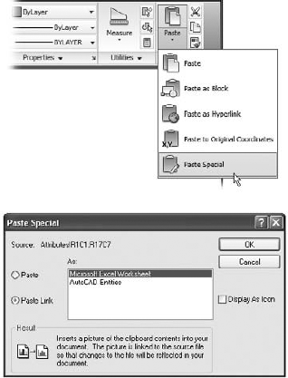
Click the Paste Link radio button to tell AutoCAD that you want this paste to be a link. Notice that the list of source types changes to show only one option: Microsoft Office Excel Worksheet. Click OK. You're prompted to select an insertion point. Place the cursor in the location for the paste, and click. The imported data appears within a bounding box. You can adjust the size of the bounding box to fit the scale of the drawing.

You can then select the type of object you want to import from the Object Type list box. Two radio buttons to the left of the list box let you import an existing object or create a new object of the type listed in the list box. If you choose the Create New radio button, the application associated with the object type will start and open a new file. If you choose the Create From File radio button (Figure 20.14), the dialog box changes to show a filename and a Browse button.

You can then browse for an existing file to import. The Link check box lets you specify whether the imported file is to be linked. If you click OLE Object to import an Excel worksheet, the entire worksheet is imported.
After you've pasted an object with links, you can control the links by typing Olelinks
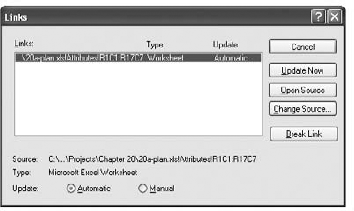
The options available in the Links dialog box are as follows:
- Cancel
Cancels the link between a pasted object and its source file. After you use this option, changes in the source file have no effect on the pasted object. This is similar to using the Bind option in the Xref command.
- Update Now
Updates an object's link when the Manual option is selected.
- Open Source
Opens the linked file in the application associated with the object and lets you edit it.
- Change Source
Lets you change the object's link to a different file. When you select this option, AutoCAD opens the Change Link dialog box, where you can select another file of the same type. For example, if you're editing the link to a sound file, the Change Link dialog box displays files with the
.wavfilename extension.- Automatic and Manual
Radio buttons that control whether linked objects are updated automatically or manually.
- Break Link
Disconnects the link between the inserted data and the source document. The inserted data then becomes embedded rather than linked.
Although it can be beneficial to import worksheets as linked OLE objects, you may prefer to import worksheets as AutoCAD entities. You may not need the direct link to the source material that OLE linking offers. The ability to edit the imported worksheet directly in AutoCAD may have a higher priority for you.
In Chapter 11, you saw how you could create tables in AutoCAD by using the Table tool. You can import an Excel worksheet as an AutoCAD table by using the AutoCAD Entities option in the Paste Special dialog box. By importing worksheets as tables, you have more control over the layout and appearance of the worksheet data.
Try the following exercise to see how you can create a table from a worksheet:
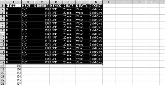
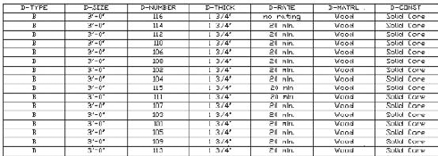
Open the Excel worksheet called
20a-plan.xls, and highlight the door data, as shown in Figure 20.16.Click Copy from the Home tab's Clipboard panel (Figure 20.17) to place a copy of the selected data into the Windows Clipboard, and then switch back to AutoCAD.
Click Paste Special from the Paste flyout on the Home tab's Clipboard panel to open the Paste Special dialog box.
With the Paste radio button selected, select AutoCAD Entities from the list and click OK.
At the
Specify insertion point or [paste as Text]:prompt, click a point in the lower-right area of the drawing. The worksheet data appears in the drawing as a table object, although it's very small (see Chapter 11 for more on tables).Use the Scale tool to enlarge the table to a readable size (Figure 20.18), and use the corner grips to adjust the width.
Close the Excel file.
You can edit this imported worksheet using the editing methods for AutoCAD tables described in Chapter 11. In that chapter, you learned that you can edit the text format, the border lineweight and color, and the background of cells. You can add rows and columns and rotate text so that it fits more uniformly in a vertical column.
In this exercise, the worksheet was imported using the default standard table style. This gives you a simple-looking table using the AutoCAD Txt font. You can set up a custom table style with the fonts and borders you want and then import the table for a more custom appearance. Make sure your custom table style is the current style before you import the worksheet.
The Paste Special dialog box offers several other options that may better suit your needs. Here is a brief description of each format that is available:
- Microsoft Document
Imports data from Microsoft Office documents. This option may show Word or Excel in the title depending on the source. The pasted object will inherit the appearance of the source document.
- Picture (Metafile)
Imports the data as vector or bitmap graphics, whichever is appropriate. If applicable, text is also maintained as text, although you can't edit it in AutoCAD.
- Bitmap
Imports the data as a bitmap image, closely reflecting the appearance of the data as it appears on your computer screen in the source application.
- Picture (Metafile)
If the image in the Clipboard contains vector data, you can use this option to paste the picture. Using this option will allow you to scale the pasted image without losing image sharpness.
- Picture (Enhanced Metafile)
Similar to the Picture (Metafile) option, with support for more features.
- AutoCAD Entities
Converts the data into AutoCAD objects such as lines, arcs, and circles. Text is converted into AutoCAD single-line text objects. Worksheets are converted into AutoCAD tables.
- Image Entity
Converts the data into an AutoCAD raster image. You can then edit it by using the raster image–related tools such as Adobe PhotoShop or the Microsoft Windows Paint program. See Chapter 14 for more on how to use raster images.
- Unicode Text
Imports text data in the Unicode format. Unicode is an international standard for encoding text. If the Text option doesn't work, try Unicode Text.
- Text
Converts the data into AutoCAD multiline text objects. Formatting isn't imported with text.
The options you see in the Paste Special dialog box depend on the type of data being imported. You saw how the Microsoft Excel Worksheet option maintains the imported data as an Excel worksheet. If the contents of the Clipboard come from another program, you're offered that program as a choice in place of Excel.
Just as you can cut and paste data into AutoCAD from applications that support OLE, you can also cut and paste AutoCAD images to other applications. This can be useful as a way of including AutoCAD images in word-processing documents, worksheets, or page-layout program documents. It can also be useful in creating background images for visualization programs such as Autodesk's 3D Studio Max and VIZ and for paint programs such as Corel Painter.
If you cut and paste an AutoCAD drawing to another file by using OLE and then send the file to someone using another computer, they must also have AutoCAD installed before they can edit the pasted AutoCAD drawing.
The receiving application doesn't need to support OLE, but if it does, the exported drawing can be edited with AutoCAD and will maintain its accuracy as a CAD drawing. Otherwise, the AutoCAD image will be converted to a bitmap graphic.
In the receiving application, choose Edit
- Find the area of closed boundaries
There are a number of ways to find the area of a closed boundary. The easiest way is also perhaps the least obvious.
- Master It
What AutoCAD feature would you use to quickly find the area of an irregular shape like a pond or lake?
- Get general information
A lot of information that is stored in AutoCAD drawings can tell you about the files. You can find out how much memory a file uses as well as the amount of time that has been spent editing the file.
- Master It
What feature lets you store your own searchable information about a drawing file, and how do you get to this feature?
- Use the DXF file format to exchange CAD data with other programs
Autodesk created the DXF file format as a means of sharing vector drawings with other programs.
- Master It
Name some of the versions of AutoCAD you can export to using the Save As option.
- Use AutoCAD drawings in page-layout programs
AutoCAD drawings find their way into all types of documents, including brochures and technical manuals. Users are often asked to convert their CAD drawings into formats that can be read by page-layout software.
- Master It
Name some file formats, by filename extension or type, which page-layout programs can accept.
- Use OLE to import data
You can import data into AutoCAD from a variety of sources. Most sources, such as bitmap images and text, can be imported as native AutoCAD objects. Other sources may need to be imported as OLE objects.
- Master It
To link imported data to a source program through OLE, what dialog box would you use?