
You can use a wealth of AutoCAD features to improve your productivity. But even with these aids to efficiency, you can always further automate in certain situations. In Part 5 of this book, you'll learn how to use AutoCAD's customization features to adapt it to fit your particular needs. I'll introduce you to some ways you can enhance AutoCAD with add-on utilities. You'll explore ways to create custom toolbars and panels and discover how you can create custom linetypes and hatch patterns.
In this beginning chapter of Part 5, you'll be introduced to customization through the AutoCAD Express tools that are supplied on the AutoCAD distribution CD. You'll also be introduced to AutoLISP, AutoCAD's macro language.
In this chapter, you'll learn to do the following:
Use enhancements straight from the source
Put AutoLISP to work
If you've followed the tutorials in this book, you've already used a few add-on programs that come with AutoCAD, perhaps without even being aware that they were not part of the core AutoCAD program. In this section, I'll introduce you to the AutoCAD Express tools: a set of AutoLISP and ARX tools that showcase these powerful customization environments. The best part about the Express tools is that you don't have to know a thing about programming to take advantage of them.
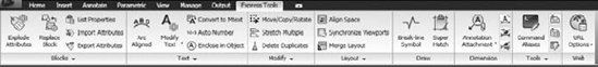
There are so many Express tools that I can't provide step-by-step instructions for all of them. Instead, I'll give you details about some of the more complicated tools and provide shorter descriptions of others. You can find the Express tools in the Express Tool Ribbon tab (Figure 26.1).
Loading the Express Tools
If for some reason, you do not see the Express Tools tab on the Ribbon, you can install the Express tools separately without having to reinstall the entire program. Choose Start
You may need to place the AutoCAD 2010 installation CD in your CD drive.
Every now and then, you'll want to use objects in a block to trim or extend to, or perhaps you'll want to copy a part of a block to another part of your drawing. In these situations, you can use the following tools. They're fairly simple to use, so the descriptions in this section should be enough to get you started.
You'll find these tools on the Blocks panel of the Express Tools tab:
- Explode Attributes
Explodes blocks containing attributes so that the attribute values are converted into plain single-line text.
- Replace Block
Replaces one set of block references with another. For example, you can replace the Tub block in the apartment plan with the Door block, turning all the bathtubs into doors. This tool works in a way similar to the Convert Block To Xref tool.
- List Properties
Displays basic information about an Xref or a block.
- Import Attributes
Enables you to import changes to the attribute information that has been exported using the Export Attribute Information tool.
- Export Attributes
Offers a quick way to extract attribute information from a block to a simple text file. You're prompted to select a file location and name and then select the attributes you want to export. The text file is formatted as a tab-delimited file. You can then edit the exported text file and use the Import Attribute Information tool (described next) to update the drawing with the modifications you made to the text file.
- Convert Block To Xref
Lets you replace block references in your drawing with Xrefs. For example, you can replace the Tub blocks in the apartment plan from earlier tutorials with an Xref of a different tub. When you select this option, the BLOCKTOXREF dialog box opens (Figure 26.2).
From here, you can select the block you want to replace. You're then asked to select a file that will be the replacing Xref.
- Copy Nested Objects
Lets you copy single objects within a block. You're allowed to select objects only individually—one click at a time.
- Extend To Nested Objects
Extends to objects in a block. This tool also works like its standard counterpart with the exception that you must select the boundary-edge objects you want to extend to individually.
- Trim To Nested Objects
Trims to objects in a block. This tool works just like the standard Trim command with the exception that you must select the cutting-edge objects individually.

It seems that we can never have enough text-editing features. Even in the realm of word processors, numerous tools let you configure fonts, paragraphs, tabs, and tables. Some programs even check your grammar. Although you may not be trying to write the great American novel in AutoCAD, you're interested in getting your text in the right location, at the right size, and with some degree of style. This often means using a mixture of text- and graphics-editing tools. The following describes some additional tools that will help ease your way through otherwise difficult editing tasks.
One problem AutoCAD users frequently face is how to get text to read clearly when it's placed over a hatch pattern or other graphic. The Hatch command hatches around existing text, leaving a clear space behind it. But what about those situations in which you need to mask behind text that is placed over a non-hatch object, such as a dimension leader or raster image?
The Text Mask tool addresses this problem by masking the area behind text with a special masking object called a Wipeout.
If you want to remove the effects of the Express Text Mask tool, choose Unmask Text from the Express Tools tab's expanded Text panel. This option prompts you to select an object. Select the masked text, and press
One of the more frustrating and time-consuming aspects of drafting is editing lengthy notes. General notes and specifications change frequently in the life of a project, so editing notes can be a large part of what you do in AutoCAD. Frequently, notes are written by someone else, perhaps a specifications writer who doesn't work directly with the drawings.
To help make note-editing easier, AutoCAD supplies the Remote Text object. This special object is linked to an external text document. Remote Text objects automatically update their contents when the source document changes.
Using Remote Text is fairly straightforward. Click the Remote Text tool from the Express Tools tab's expanded Text panel, or type Rtext
Besides the text tools already described, several others can help to simplify some common text-related operations. Table 26.l offers a description of these other tools.
Table 26.1. Tools on the Text Panel
Tool Name | Function |
|---|---|
Arc Aligned | Draws text along an arc |
Modify Text | A flyout that offers tools to explode, change case, rotate, fit, or justify text |
Convert to Mtext | Converts single-line text created with Text or Dtext into multiline text |
AutoNumber | Adds numbers to a text list |
Enclose in Object | Encloses text in a circle, slot, or rectangle |
The Express Tools Modify panel seems to be the answer to most AutoCAD users' wish lists. As with many of the Express tools discussed so far, these tools have been floating around in the AutoCAD user community as AutoLISP utilities. Stretch Multiple lets you use the crossing polygon selection option to select endpoints and vertexes for stretching. The Move/Copy/Rotate tool combines these three functions into one command. Delete Duplicates removes duplicate objects that may be hidden by overlapping objects.
In the earlier part of this chapter, you saw the tools on the Block panel. There are two more block-related tools that have a more general use, so they've been placed in the Modify panel.
- Extended Clip
In Chapter 7, you saw how to limit the display of an Xref to an L-shaped, rectilinear area. Extended Clip adds the ability to use arcs, circles, and polylines to clip the view of an Xref.
- Convert Shape To Block
Converts a shape object into a block. You can then explode the block to its component objects if needed.
In Chapter 7, you saw how you can clip an Xref or a raster image so that only a portion is visible. One limitation to the Raster Clip option is that you can clip only areas defined by straight lines. You can't, for example, clip an area defined by a circle or an ellipse.
Extended Clip is designed for those instances when you absolutely need to clip a raster image to a curved area. The following steps show you how it works:
Create a clip boundary by using a curved polyline or circle.
Choose Extended Clip from the Express Tools tab's expanded Modify panel.
Click the boundary.
Click the Xref, block, or image you want to clip.
At the following prompt, press

Enter maximum allowable error distance for
resolution of arc segments <7--16">:
The Xref, block, or image clips to the selected boundary.
You can erase the boundary you created in step 1 or keep it for future reference.
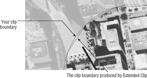
Extended Clip doesn't really clip to the boundary you created but instead approximates that boundary by creating a true clip boundary with a series of very short line segments. The prompt in step 5 lets you specify the maximum allowable distance between the straight-line segments it generates and the curve of the boundary you create (see Figure 26.3).
AutoCAD includes some Express tools that will help make your work with layouts a lot easier. These tools, found in the Express Tools tab's Layout panel, address some of the more common operations you'll encounter as you work with layouts.
If you've ever tried to align an object in a layout with objects in a Model Space viewport, you know how difficult it can be. This situation often arises when you accidentally pan or zoom a Model Space viewport, and objects drawn in Paper Space (such as break lines or dimensional notations) become misaligned with the underlying view.
The Align Space tool helps you quickly align objects in a Model Space viewport with objects in the layout Paper Space. Align Space can even rotate a viewport view to align objects that are at an angle. To see how it works, try the following exercise. You'll align a plan view of a set of survey data points to a north arrow in Paper Space:
Open the
alignspace.dwgsample file.Choose Align Space from the Layout panel. The viewport automatically becomes active.
At the
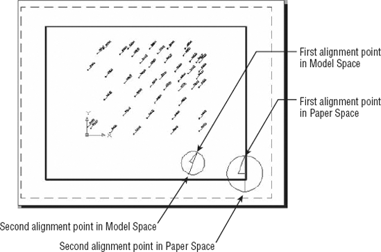
FIRST alignment point in MODEL space:prompt, click the upper endpoint of the north arrow in the viewport, as shown in Figure 26.4.At the
SECOND point in MODEL space or <Return> for none:prompt, click the endpoint of the bottom end of the north arrow, as shown in Figure 26.4.At the
FIRST alignment point in PAPER space:prompt, AutoCAD automatically switches to Paper Space to allow for your next input. Click the upper endpoint of the layout Paper Space north arrow.At the
SECOND alignment point in PAPER space:prompt, click the lower end of the Paper Space arrow. The two arrows align, and a message tells you the scale of the viewport.
In this exercise, the two north arrows were aligned in both scale and direction. The object you're aligning to in Paper Space doesn't have to be in the area of the viewport, either.
If you prefer, you can align a single point without changing the scale or rotation of the viewport by pressing
The Align Space tool lets you align a Model Space object to a Paper Space object—but what if you want to align two Model Space views? For example, suppose you want to overlap two viewports of the same view, with one viewport displaying graphics while the other displays just the power and signal symbols for a small region of the plan.
The Synchronize Viewports tool lets you do just that. It aligns one or more viewports to another master viewport. The Synchronize Viewports tool aligns the coordinates in one viewport with the coordinates and scale of another so the views are matched like pieces of a jigsaw puzzle. To get a better idea of what this means, try the following exercise. Suppose you have an enlarged plan showing a portion of a building. You want to include the grid lines in your plan, but you don't want to have to include other portions of the plan or redraw the grids. Synchronize Viewports makes easy work of this project:
Open the
synchronize.dwgfile, and then choose Synchronize Viewports from the Layout panel.Click the border of the viewport in the lower-right corner.
At the
Select viewports to be aligned to master viewport.Select objects:prompt, click the other two viewports, and press
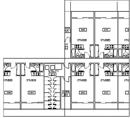
The three views of the layout combine to show a contiguous Plan view instead of three random views (Figure 26.5).
You could use Synchronize Viewports this way to piece together parts of a floor plan in a nonrectangular shape.
To finish adding the grid lines, do the following:
Double-click in the top viewport, and then click the Pan tool in the status bar.
Shift+click and drag the view downward to bring the grid lines into view. Then, Shift+click and drag and keep the pan motion in an exact vertical direction. Pan downward until you see only the grids and dimensions.
Press Esc to exit the Pan tool; then double-click the left viewport and use the Pan tool to Shift+click and drag the view toward the right. Keep panning until just the grid lines show (Figure 26.6).
If you've ever tried to do this operation without the aid of the Synchronize Viewports tool, you can see how helpful a tool it is.
The Layout panel includes two more fairly simple tools: List Viewport Scale and Merge Layout. List Viewport Scale does just what its name says. Choose List Viewport Scale from the expanded Layout panel, and then click a viewport border to display the viewport scale. Merge Layout combines the contents of one layout with another. This tool is handy if you're exporting files to earlier versions of AutoCAD in which only one layout is possible. Choosing Merge Layouts from the Layout panel opens the LAYOUTMERGE dialog box. This dialog box is a list showing the layouts in the current drawing.
You can select the layout that you want merged with the current layout. After you make your selection and click OK, another dialog box appears that looks identical to the first LAYOUTMERGE dialog box. This time, you select the destination layout for the merged layouts.
That covers the Express layout tools. As with many of the other Express tools, you may find yourself using these tools more than the other standard AutoCAD commands; keep them in mind as you work on the layout of your next set of drawings.
Two tools offer functions not found in the rest of the AutoCAD program: Break-Line Symbol and Super Hatch. The Break-Line tool is a very easy-to-use tool that just draws a break line. It is a command-line tool that offers options to use a custom block for the break symbol, adjust the size of the break symbol, or to set the extension distance for the break line.
The Super Hatch tool is quite powerful because it allows you to create a custom hatch pattern from just about anything, including image files. This tool is a bit more complicated, so it requires a bit more information to master.
You can access a number of hatch patterns from AutoCAD's Hatch And Gradient dialog box, but at times none of those patterns will fulfill your needs. This is where the Super Hatch tool comes in. With Super Hatch, you can create virtually any hatch pattern you want. You can use objects in your drawing as a basis for a hatch pattern, or you can import bitmap images and use them to form a hatch pattern, such as tiled wallpaper in the Windows Desktop background.
The following exercise shows you how to use Super Hatch:
Open the
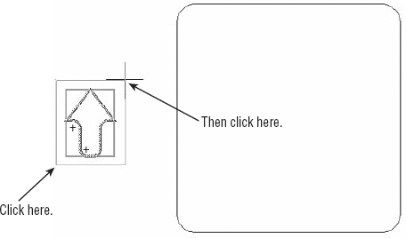
superhatch.dwgfile. You see a block of an arrow on the left side of the screen and a rectangular area to the right. In this exercise, you'll turn the arrow into a hatch pattern.
Click the Select Existing button to close the SuperHatch dialog box.

At this point, you can indicate the area you want repeated in your pattern. The default is the extents of the selected item, as indicated by the magenta rectangle.
Click the two points shown in Figure 26.8 to indicate the area that you want repeated. The rectangle changes to reflect the new area. You can repeat the area selection as many times as you need until you get exactly the area you want.
Press
Click the interior of the rectangle to indicate the area you want to hatch. If you have multiple hatch areas, you can continue to select them at this step.
Press


The object you select by using the Select Existing option in the SuperHatch dialog box must be a block. You can modify that block by using the techniques described in Chapter 7 and the changes will appear in the hatch pattern, as shown in Figure 26.10.
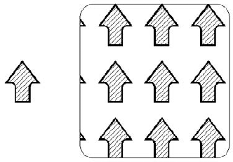
Figure 26.10. The custom hatch pattern after the arrow block has been modified to include the diagonal hatch pattern
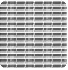
As you can see from the SuperHatch dialog box, you can incorporate Xrefs, blocks, and even image files into your custom hatch pattern. Each of these options prompts you to insert the object before you convert it into a hatch pattern. You use the usual insertion method for the type of object you select. For example, if you choose the Block option, you're prompted for an insertion point, the X and Y scale factors, and a rotation angle. For image files, you see the same dialog box that you see when you insert an image file, offering the options for insertion point, scale, and rotation. Figure 26.11 shows a sample hatch pattern with an image file used instead of an AutoCAD block.
Early in AutoCAD's history, the dimension feature was almost like its own program within AutoCAD. A user would have to enter the dimension command, add whatever dimensions were needed, and then exit the dimension command. Dimensioning is much easier now, but it is still a complex feature that can require some additional help from outside the standard dimensioning feature set.
The Dimension panel offers several tools that simplify some of the more common editing tasks for dimensions. The Annotation Attachment flyout offers tools that let you add or remove leaders to annotation. The Reset Dim Text Value tool lets you reset the text of a dimension that has been overridden or otherwise modified.
Perhaps the most frequently used dimension-related tools are the Dimstyle Export and Import tools. Dimstyles can take a fair amount of time to set up, and they contain a lot of settings that would be difficult to remember. If you're moving from one computer to another or from one office to another, the dimstyle tools can save a lot of time and effort.
Most AutoCAD users need to set up their dimension styles only once and then make minor alterations for drawing scale. You can set up your dimension styles in a template file and then use that template whenever you create new drawings. That way, your dimension styles will already be set up the way you want them.
But frequently, you'll receive files created by someone else, and they may not have the same ideas about dimension styles as you do. Normally, this would mean you'd have to re-create your favorite settings in a new dimension style. With the Express tools Dimstyle Export and Dimstyle Import options, you can export and import dimension styles at any time, saving you the effort of re-creating them.
Besides the tools you've seen so far, there are several that don't fit into a neat category. The Tools panel of the Express Tools tab contains a mix of tools that let you do everything from creating and editing your command aliases to creating new line types.
Throughout this book, I've been showing you the keyboard shortcuts to the AutoCAD commands. In Windows, all these shortcuts are stored in a file called Acad.pgp in the C:Documents and Settings folder. (Check the Working Support File Search Path option in the Files tab in the Options dialog box to find the exact location for the support files on your system.) In the past, you had to edit this file with a text editor to modify these command shortcuts (otherwise known as command aliases). But to make our lives simpler, Autodesk has supplied the Command Alias Editor, which automates the process of editing, adding, or removing command aliases in AutoCAD.UsernameApplication DataAutodeskAutoCAD 2010R18.0enuSupport
In addition, the Command Alias Editor lets you store your own alias definitions in a separate file. You can then recall your file to load your own command aliases. Here's how the Command Alias Editor works:
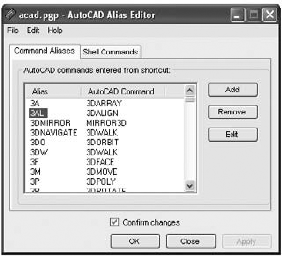
Choose Command Aliases from the Tools panel to open the AutoCAD Alias Editor dialog box (Figure 26.12).
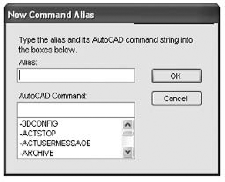
As you can see from the button options, you can add, delete, or edit an alias. Click the Add button to open the New Command Alias dialog box (Figure 26.13).
In this dialog box, you enter the desired alias in the Alias input box and then select the command from the AutoCAD Command list box. You can also enter a command or macro name, such as Wipeout, in the input box. When you click the Edit option in the AutoCAD Alias Editor dialog box, you see a dialog box identical to this one with the input boxes already filled in.
After you create or edit an alias, click OK to return to the AutoCAD Alias Editor dialog box.
Click OK to exit the dialog box. A warning message tells you that you're about to overwrite the
Acad.pgpfile.Click Yes to update the
Acad.pgpfile.
If you're a veteran AutoCAD user, you may be accustomed to your own set of command aliases. If so, you may want to create your own PGP file containing just your custom aliases. Then, whenever you use AutoCAD, you can open the AutoCAD Alias Editor, choose File
Most of the time, the linetypes provided by AutoCAD are adequate. But if you're looking for that perfect linetype, you can use the Make Linetype tool to create your own. Here's how it works:
Open the
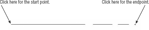
customltype_completed.dwgsample file from theFiguresfolder. The sample drawing is made up of simple lines with no polylines, arcs, or circles. When you create your own linetype prototype, make sure the lines are all aligned. Draw a single line, and break it to form the segments of the linetype (see Figure 26.14). Also make sure it's drawn to the actual plotted size.Choose Make Linetype from the expanded Tools panel to open the MKLTYPE dialog box. This is a typical save dialog box allowing you to create a new linetype file.
Enter myltype for the filename, select a location for the file, and then click Save.
At the
Enter linetype name:prompt, enter MyLinetype or any name you want to use for the linetype. The name must be a single word.At the
Enter linetype description:prompt, enter a description for your linetype. This can be a sentence that best describes your linetype.At the
Specify starting point for line definition:prompt, pick one endpoint of the sample linetype.At the
Specify ending point for line definition:prompt, pick a point just past the opposite end of the sample linetype. Pick a point past the endpoint of the sample to indicate the gap between the end of the first segment of the linetype and the beginning of the repeating portion, as shown in Figure 26.14.At the
Select objects:prompt, select the sample linetype lines. When you're done, press
If you send your file to someone else, you need to make sure you include your custom linetype files with the drawing file. Otherwise, anything drawn using your custom linetype will appear as a continuous line, and your recipient will get an error message saying that AutoCAD can't find a linetype resource.
The Make Linetype tool creates a single linetype file for each linetype you create. The linetype file is a simple ASCII text file. If you end up making several linetypes, you can combine your linetype files into one file by using a simple text editor such as Windows Notepad. Don't use WordPad or Word because these programs will introduce special codes to the linetype file.
Shapes are special types of AutoCAD objects that are similar to blocks. They're usually simple symbols made up of lines and arcs. Shapes take up less memory and can be displayed faster, but they're much less flexible than blocks, and they aren't very accurate. You can't use object snaps to snap to specific parts of a shape, nor can you explode shapes. They're best suited for symbols or as components in complex linetypes.
Shapes have always been difficult to create. In the past, you couldn't create a shape by drawing it. You had to create something called a shape definition by using a special code. A shape definition is an ASCII file that contains a description of the geometry of the shape. Creating such a file was a tedious, arcane process and few users bothered to do it.
With the introduction of complex linetypes in recent versions of AutoCAD, interest in shapes has revived. To make it easier for users to create shapes, AutoCAD 2010 provides a tool that creates a shape definition file for you based on a line drawing. Try this simple exercise to learn how to create and use a shape:
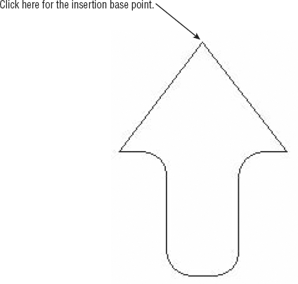
Open the
makeshape.dwgsample file from the Chapter 26 folder of the sample project files. This file contains a simple drawing of an upward-pointing arrow. It contains lines and arcs.Choose Make Shape from the expanded Tools panel to open the MKSHAPE dialog box. This is a typical save dialog box that enables you to specify a name and location for your shape definition file.
In the File Name input box, enter Arrow; then, locate the
My Documentsfolder and place your new file there.Click OK to create your file.
At the
Enter the name of the shape:prompt, enter ArrowAt the
Enter resolution <128>:prompt, enter 512At the
Specify insertion base point:prompt, select the tip of the arrow, as shown in Figure 26.15. This will be the insertion point of your shape, which is similar to the insertion point of a block.At the
Select objects:prompt, select the entire arrow, and then pressA series of messages tells you what AutoCAD is doing. The last message tells you whether AutoCAD was successful in creating the shape file, and it tells you the location and name of the new shape file:
Compilation successful.  Output file C:Documents and SettingsUser NameMy
   DocumentsArrow.shx contains 309 bytes.

Shape "ARROW" created.
Use the SHAPE command to place shapes in your drawing.
To see how your shape came out, try the following. Here you'll learn how to load and insert a shape:
At the Command prompt, type Load
In the
My Documentsfolder, locate the fileArrow.shx, and click Open to load it.Type Shape
At the
Enter shape name or [?]:prompt, type ArrowAt the
Specify insertion point:prompt, click to the right of the original arrow.At the
Specify height:prompt, pressAt the
Specify rotation angle:prompt, enter 45
In many ways, a shape acts like a block, but you can't snap to any of its points. It's also less accurate than a block in its representation, although for some applications this may not be a great concern. Finally, you can't use complex shapes such as 3D objects for your shape; you can use only lines and arcs.
Still, you may find shapes useful in your application. As mentioned earlier, you can include shapes in linetype definitions. See "Creating Complex Linetypes" in Chapter 28 for a description of how to create a linetype that includes shapes as part of the line.
This set of options is less likely to get as much use as the others you've looked at so far, so I've included a brief description of them here without going into too much detail. They're fairly easy to use, and you shouldn't have any trouble trying them. You can access both tools from the Tools panel:
- Attach Xdata
Lets you attach extended data to objects. Extended data is usually used only by AutoLISP or ARX applications. You're asked to select the object that will receive the data, and then you're asked for an application name that serves as a tag to tell others the name of the person to whom the data belongs. You can then select a data type. After this is done, you can enter your data.
- List Object Xdata
Displays extended data that has been attached to an object.
AutoCAD enables you to add URL links to objects. This is a great feature that can help you link drawings to other types of data. The Express Web tools on the Web panel add some enhancements to the URL linking features of AutoCAD:
- Show URLs
Displays the URL link attached to an AutoCAD object.
- Change URLs
Lets you quickly edit an object's existing URL. You must still choose Insert

- Find And Replace URLs
Replaces a set of existing URLs with a URL of your specification.
In previous version of AutoCAD, many of the Express tools could only be found in the menu bar under the Express menu. In AutoCAD 2010, many of those tools do not appear in the Ribbon, but you can still use them by entering their keyboard command names. You can also find these tools in the Express Tools menu if you enable the menu bar. The following section describes these tools along with the keyboard commands you'll need to use them.
AutoCAD has always made extensive use of external files for its operation. Everything from fonts to keyboard shortcuts depends on external files. The Express File tools offer options to simplify a few file-related operations. You may find some of these tools, such as Save All Drawings and Close All Drawings, helpful on a daily basis. Others may be useful to know about, such as Edit Image when you need to edit an image. The following is a list of these tools:
- Move Backup Files (Moveback)
Lets you specify a location for AutoCAD BAK files for the current drawing session.
- Convert PLT To DWG (Plt2dwg)
Converts HPGL plot files to drawing files. You must first set up AutoCAD or Windows for an HPGL plotter and then specify that HPGL plotter in the Plot Or Page Setup dialog box. You must also indicate that you want to plot to a file at the time you produce the plot (select the Plot To File check box in the Printer/Plotter group of the Plot dialog box).
- Edit Image (Imageedit)
Offers a quick way to open and edit an image file that has been inserted into an AutoCAD drawing. Type Imageedit
- Redefine Path (Redir)
Lets you redefine the path to external files that are referenced from the current drawing. This includes Xrefs, images, shapes, styles, and Rtext. You can strip a path from a referenced file by using the asterisk option (*) when you see the
Enter old directory (use '*' for all), or ? <options>:prompt. When you see theReplace "*" with:prompt, press- Update Drawing Property Data (Propulate)
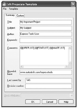
Drawing property data can be a handy feature of AutoCAD, but using it requires some discipline. (See Chapter 20 for more on drawing property data.) For one thing, the amount of data you must enter can be a bit daunting. The Update Drawing Property Data Express tool offers a way to let you quickly add drawing property data by utilizing property data templates. Drawing property data is often the same for a set of drawings, so you can create a template and apply it to similar drawings in a set by using the Update Drawing Property Data tool.
To create a drawing property data template, type Propulate
Fill in the data, click OK, and then choose Save As from the Application menu. Use the Update option in the Update Drawing Property Data Command prompt to apply the template to a drawing or to a set of drawings in a folder.
- Save All Drawings (Saveall)
Saves all currently open files. The files remain open for additional editing.
- Close All Drawings (Closeall)
Closes all currently open drawings. AutoCAD remains open.
- Quick Exit (Qquit)
Closes all currently open drawings, and exits AutoCAD. You're asked whether you want to save changes to each file before it's closed.
- Revert To Original (Revert)
Causes a drawing to revert to its last saved state. It does so by closing the file without saving any changes (since the last Save) and then reopening the file.
Sometimes it seems that there aren't enough selection tools available in AutoCAD. In Chapter 2, you learned about the various methods you can use to select groups of objects (thereby building a selection set, which is a set of objects selected for an operation such as a move or copy). The Express tools offer a few more ways to select objects.
The Get Selection Set tool (Getsel) sets up a selection set based on layers or types of objects. When you type Getsel
Another selection tool is Fast Select (Fastsel). When you type Fastsel
Most high-end CAD packages offer a macro or programming language to help users customize their systems. AutoCAD has AutoLISP, which is a pared-down version of the popular LISP artificial intelligence language.
Don't let AutoLISP scare you. In many ways, an AutoLISP program is just a set of AutoCAD commands that help you build your own features. The only difference is that you have to follow a different set of rules when using AutoLISP. But this isn't so unusual. After all, you had to learn some basic rules about using AutoCAD commands too—how to start commands, for instance, and how to use command options.
If the thought of using AutoLISP is a little intimidating, bear in mind that you don't need substantial computer knowledge to use this tool. In the following sections, you'll see how to get AutoLISP to help out in your everyday editing tasks, without having to learn the entire programming language.
Many AutoCAD users have discovered the usefulness of AutoLISP through the thousands of free AutoLISP utilities that are available from websites and online services. It's common for users to maintain a toolbox of their favorite utilities on a disk. But before you can use these utilities, you need to know how to load them into AutoCAD. In the following exercise, you'll load and use a sample AutoLISP utility:
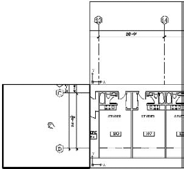
Start AutoCAD, and open the
24-unit.dwgfile.
Click the Load button. The message
GETAREA.LSP successfully loadedappears in the message box at the bottom of the dialog box. If you scroll down the list in the Loaded Applications tab, you also seeGETAREA.lsplisted there, which tells you that it's loaded.Click Close to close the Load/Unload Applications dialog box.
Enter getarea
At the
Pick point inside area to be calculated:prompt, click inside the unit plan.At the
Select location for area note:prompt, pick a point just above the door to the balcony. A label appears, displaying the area of the room in square feet.
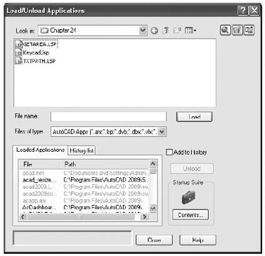
You've just loaded and used an AutoLISP utility. As you saw in the Load/Unload Applications dialog box, you can load and try several other utilities. Next, you'll look more closely at the Load/Unload Applications dialog box.
The Load/Unload Applications dialog box gives you plenty of flexibility in managing your favorite AutoLISP utilities. You can also manage your ARX applications. As you saw in the previous exercise, you can easily find and select utilities by using this dialog box. If you often use a custom application, you can include it in the History List tab of the Load/Unload Applications dialog box, as you'll see in the following steps:

Select the Add To History check box.
Click the History List tab.
Select
GETAREA.LSPfrom the list of applications at the top of the dialog box.Click Load.
GETAREA.LSPnow appears in the History List tab (Figure 26.18).Click Close to close the Load/Unload Applications dialog box.

Now when you exit AutoCAD, the dialog box retains the name of the GETAREA.LSP utility in the History List tab. When you want to load GETAREA.LSP in a future session, you won't have to hunt it down. You can highlight it in the History List tab and then load it from there. You can add as many items as you want to your History List tab or remove items by highlighting them and clicking the Remove button. The History List tab works with all types of applications that AutoCAD supports.
As you start to build a library of AutoLISP applications, you may find that you use some of them all the time. You can set up AutoCAD to load your favorite applications automatically. To do this, you use the Startup Suite in the Load/Unload Applications dialog box:
Choose Load Application from the Manage tab's Applications panel to open the Load/Unload Applications dialog box.
Click the Contents button or the suitcase icon in the Startup Suite group to open the Startup Suite dialog box. This dialog box contains a list box that shows any applications that are to be started whenever AutoCAD starts. You add applications with the Add button at the bottom. If there are applications in the list, you can use the Remove button to remove them.
Click the Add button to open the Add File To Startup Suite dialog box. This is a typical file open dialog box that enables you to search for and select a file.
Locate and select the
GETAREA.LSPfile in the Chapter 26 folder and click Add. The Startup Suite dialog box reappears andGETAREA.LSPis listed.Click Close, and then click Close again in the Load/Unload Applications dialog box.
From now on, GETAREA.LSP will be loaded automatically whenever you start AutoCAD. You can add several files to the Startup Suite list.
You can write simple AutoLISP programs of your own that create what are called keyboard macros. Macros—like script files—are strings of predefined keyboard entries. They're invaluable for shortcuts to commands and options you use frequently. For example, you might often use the Break command to break an object at a single point while editing a particular drawing. Here's a way you can turn this operation into a macro:
Close the
24-unit.dwgfile without saving it, and then open it again and enter the following text at the Command prompt. Be sure you enter the line exactly as shown here. If you make a mistake while entering this line, you can use the I-beam cursor or arrow keys to go to the location of your error to fix it:(defun C:breakat () (command "break" pause "f" pause "@"))
Enter breakat
Click the wall on the right side of the unit.
At the
Specify first break point:prompt, click a point on the wall where you want to create a break, and make sure Osnaps are turned off.To see the result of the break, click the wall again. It's been split into two lines, as shown in Figure 26.19.

You've just written and run your first AutoLISP macro! Let's take a closer look at this simple program (see Figure 26.20). It starts with an opening parenthesis, as do all AutoLISP programs, followed by the word defun. Defun is an AutoLISP function that lets you create commands; it's followed by the name you want to give the command (Breakat, in this case). The command name is preceded by C:, telling defun to make this command accessible from the Command prompt. If the C: were omitted, you would have to start Breakat by using parentheses, as in (Breakat).
After the command name is a set of opening and closing parentheses. This set encloses what is called the argument list. The details aren't important; just be aware that these parentheses must follow the command name.
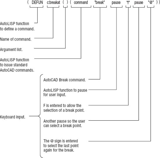
Finally, a list of words follows enclosed by another set of parentheses. This list starts with the word command. Command is an AutoLISP function that tells AutoLISP that whatever follows should be entered just like regular keyboard input. Only one item in the Breakat macro—the word pause—isn't part of the keyboard input series. Pause is an AutoLISP function that tells AutoLISP to pause for input. In this particular macro, AutoLISP pauses to let you pick an object to break and the location for the break.
Most of the items in the macro are enclosed in quotation marks. Literal keyboard input must be enclosed in quotation marks this way. The pause function, on the other hand, doesn't require quotation marks because it's a proper function, one that AutoLISP can recognize.
The program ends with a closing parenthesis. All parentheses in an AutoLISP program must be in balanced pairs, so these final two parentheses close the opening parenthesis at the start of the command function as well as the opening parenthesis back at the beginning of the defun function.
When you create a program at the Command prompt, as you did with the Breakat macro, AutoCAD remembers it only until you exit the current file. Unless you want to re-create this macro the next time you use AutoCAD, save it by copying it into an ASCII text file with an .lsp filename extension using the Windows Notepad application. Figure 26.21 shows a file named Keycad.lsp, which contains the saved Breakat macro along with some other macros I use often.

The other macros are commands that include optional responses. For example, the third item, defun c:frz, causes AutoCAD to start the Fillet command, enter an R
After the file is loaded, you can use any of the macros in it by entering the macro name. For example, entering ptx
Macros loaded in this manner are available to you until you exit AutoCAD. Of course, you can have these macros loaded automatically every time you start AutoCAD by including the Keycad.lsp file in the Startup Suite of the Load/Unload Applications dialog box. That way, you don't have to remember to load it in order to use the macros.
Now that you have some firsthand experience with AutoLISP, I hope these examples will encourage you to try learning more about this powerful tool.
Record and Play Back Actions
If AutoLISP seems a bit too intimidating but you still need a way to automate certain tasks, the Action Recorder is a feature you'll want to explore. The Action Recorder enables you to record a series of actions in AutoCAD and store them as action macros. You can play back your action macros at any time. This is a great time-saver when you are performing repetitive tasks, something that you may find yourself doing frequently in AutoCAD.
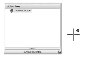
An entire panel is devoted to the Action Recorder in the Tools tab.
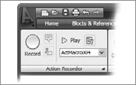
To use the Action Recorder, click the Record button. The Record button changes to a Stop button, and a red dot appears next to the cursor to remind you that you are recording your activity. You'll also see the Action Tree appear just below the recorder.
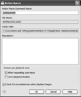
Proceed to work as you normally would in AutoCAD. As you work, your activity is displayed in the Action Tree. When you've completed the activity that you want to record, press the Stop button. The Action Macro dialog box appears, enabling you to give the recorded activity a name and description.
Once you've closed the Action Macro dialog box, you can play back your recorded action macro at any time. From the Action Recorder panel, select the macro name from the Available Action Macro drop-down list and then click Play.
The Action Tree enables you to include some interactivity in your macro. You can right-click on an individual action in the Action Tree to modify its behavior to allow user input. Perhaps the most common modification you'll want to make is to allow different selections or to change coordinate input and point selections. To do this, right-click on an action and select Request User Input.
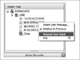
Upon selecting this option, you will be prompted for input when this particular action comes up in the macro. You can also use the Insert User Message option to have a message display while the macro is running. Messages can be helpful for users unfamiliar with your macro.
- Use enhancements straight from the source
The Express tools have been around for a while and were originally intended to show what could be done with customization. Many users have come to rely on some of these tools.
- Master It
Which of the toolbars described in this chapter is a former Express toolbar that became part of the main program?
- Put AutoLISP to work
AutoLISP is a macro language that gives you the ability to create your own commands.
- Master It
Name the filename extension for AutoLISP programs.