
Whether you're a one-person operation working out of your home or one of several hundred AutoCAD users in a large company, file sharing and file maintenance can become the focus of much of your time. In our interconnected world, the volume of messages and files crossing our paths seems to be on the rise constantly. In addition, the Internet has enabled us to be more mobile, adding yet more complexity to file-management tasks.
In this chapter, you'll learn about some of the tools AutoCAD offers to help you manage your files and the files you share with others. You'll also examine some general issues that arise while using AutoCAD in a workgroup environment. You may find help with problems you've encountered when using AutoCAD in your particular work environment in the discussion throughout the chapter.
In this chapter you'll learn to do the following:
Share drawings over the Internet
ePublish your drawings
Manage your drawings with DesignCenter and the Tool palettes
Establish office standards
Convert multiple layer settings
The Internet has become a major part of our daily working lives. It provides AutoCAD users with some real, practical benefits by giving them the ability to publish drawings and other documents online. AutoCAD gives you tools that enable you to post drawings on the Internet that others can view and download. In the architecture, engineering, and civil (AEC) industry in particular, this can mean easier access to documents needed by contractors, engineers, cost estimators, and others involved in the design, bidding, and construction of architectural projects. Suppliers of products can post symbol libraries of their products or even 3D solid models.
In the following sections, you'll learn about the tools AutoCAD provides for publishing and accessing drawings over the Internet (and on any local or wide area network). You'll start by looking at one of the most common uses of the Internet: file transmission.
Perhaps the most common use of the Internet is sending and receiving files. Whether you're a 1-person office or a member of a 50-person firm, you'll eventually have to share your work with others outside your building. Before eTransmit existed as a feature in AutoCAD, you had to examine what you were sending carefully to make sure you included all the ancillary files needed to view or work on your drawings. Xref, font, and custom linetype files all had to be included with the drawings that you sent to consultants or partners in a project, and often one of these items was omitted from the transmission.
By using eTransmit, you can quickly collect all your project drawings into a single archive file, or you can store the files in a separate folder for later processing. This collection of files is included with a report file as a transmittal. Try the following to see how eTransmit works:
In AutoCAD, open a file you intend to send to someone and then choose Send

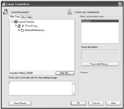
In the dialog box, a tree structure lists the files that are included in the transmittal. If you need to add more files to the transmittal than are shown in the list, you can click the Add File button to open a file dialog box. To remove files, expand the listed item and remove the check mark that appears next to the file you want to exclude. You can also use the Files Table tab to view the files as a simple list.
Click in the Enter Notes To Include With This Transmittal Package input box, and enter a description or other note.
In the Select A Transmittal Setup group, click the Transmittal Setups button to open the Transmittal Setups dialog box (Figure 29.2). From here, you can create a new transmittal or rename or modify an existing one.
Click the Modify button to open the Modify Transmittal Setup dialog box (Figure 29.3).
In the Transmittal Package Type drop-down list, select the format for your collection of files. You can create a Zip or self-extracting executable archive, or you can save the files in a folder. If you choose the Zip or executable option, you can also add a password by selecting the Prompt For Password check box in the Actions group of the dialog box. The person receiving the transmittal file must then enter a password to extract the files. If you choose the Folder option, you can tell AutoCAD where to place the files by using the Browse button to the right of the Transmittal File Folder drop-down list. For this exercise, choose the Folder option in the Transmittal Package Type list.
Click the Browse button to open the Specify Location Folder dialog box. This is a typical AutoCAD file dialog box that you can use to select a location for your files. You can use the Create New Folder tool to create a new folder for your files. You'll want to keep your transmittal files separate from other files. After you select a location, you return to the Modify Transmittal Setup dialog box.
After you've set up your transmittal, click OK. Then click Close in the Transmittal Setups dialog box.
Preview the report file by clicking the View Report button in the Create Transmittal dialog box. This report gives you a detailed description of the types of files included in the transmittal. It also alerts you to files that AutoCAD was unable to find but that are required for the drawing.
After you've set up the eTransmit options, click OK in the Create Transmittal dialog box.
If you selected the Zip option in step 6, you see the Specify Zip File dialog box. Enter a name and a location for the file and AutoCAD collects the files into an archive folder or a Zip file. You can then send the files over the Internet or put them on a removable disk for manual transport. The EXE option works in a similar way.
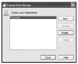

You probably noticed that you can create additional transmittal setup options in the Transmittal Setups dialog box. That way, you can have multiple transmittal options on hand that you don't have to set up each time a different situation arises. For example, you might have the Standard setup configured to create a Zip file and another setup configured to copy the files into a folder. A third setup might be created with a password.
Several options are available for configuring the transmittal setup. Table 29.l gives a rundown of those options.
Table 29.1. Modify Transmittal Setup Dialog Box Options
Option | Purpose |
|---|---|
Transmittal Package Type | Lets you select Folder, Zip, or Executable Zip file. |
File Format | Lets you select 2010, 2007, 2004, or 2000 file formats in case your recipient requires an earlier version. |
Transmittal File Folder | Lets you determine the location for your transmittal package. |
Transmittal File Name | Not available if you select Folder as the transmittal package type. Options are Prompt For A File Name, Overwrite If Necessary, and Increment File Name If Necessary. |
Preserves the folder structure for the files in the transmittal. This can be important when Xref and other files are located across several folder locations. | |
Place All Files In One Folder | Self-explanatory. |
Keep Files And Folders As Is | Preserves the entire folder structure for the files in the transmittal. |
Include Fonts | Tells AutoCAD to include the font files in the transmittal. |
Include Textures From Materials | Lets you include bitmap files that are part of a file's material settings. |
Include Files From Data Links | Lets you include external data-link files for tables. |
Include Photometric Web Files | Lets you include photometric web files for 3D lighting models. |
Send E-Mail With Transmittal | Lets you send an e-mail with the files included as an attachment. |
Set Default Plotter To 'None' | Removes any reference to printers or plotters that you've set up for the drawing. (The type of printer you've set up for your files is stored with the drawing file.) |
Bind External References | Lets you bind external references to the drawings that contain them if it isn't important for the recipient to maintain the external references as separate drawings. |
Prompt For Password | Gives you the option to password-protect the transmittal file. |
Purge Drawings | Purge drawings of unused elements. |
eTransmit gives you a quick way to package a set of files to be sent to others working on the same project. But you may need to offer a wider distribution of your files. You might want to let others view and plot your drawings from a website without exposing your drawing database to anyone who might visit your site. If this sounds like something you're interested in, you'll want to know about the AutoCAD DWF file format, which lets anyone view AutoCAD files whether they own the program or not. You'll learn more about the DWF file format in the section "ePublishing Your Drawings" later in this chapter.
Because AutoCAD drawings specify the methods and materials used to produce an object or a building, the drawings are frequently treated like legal documents. After an AutoCAD drawing is issued, it's often archived and guarded as a legal record of a design. For this reason, many AutoCAD users are concerned about possible tampering with drawings that are sent to third parties. Even minor, unauthorized changes to a drawing can have major repercussions to the integrity of a design.
AutoCAD 2010 offers tools that can help minimize file tampering. The eTransmit feature offers a password-protection option to reduce the possibility of unauthorized tampering with transmittal files. AutoCAD also offers password protection for individual files as well as a digital-signature feature that helps protect both the author of a drawing and the recipient in the event of file tampering.
The basic type of file protection is the password protection of individual files. AutoCAD offers password protection through the Save Drawing As dialog box and the Options dialog box.
To add a password to a drawing when you save it, do the following:
Choose Save As from the Application menu to open the Save Drawing As dialog box.
Choose Tools
In the Security Options dialog box, enter a password or phrase in the input box.
Click OK. You're prompted to enter the password again.
Enter the password again, and click OK to return to the Save Drawing As dialog box.
Enter the name and location of your file, and then click Save.
In addition to the Save Drawing As dialog box, you can add password protection through the Options dialog box:
Choose Options from the Application menu to open the Options dialog box, and then click the Open And Save tab.
Click the Security Options button in the File Safety Precautions group to open the Security Options dialog box.
Enter your password, select other options as necessary, and then click OK.
As a third option, you can enter Securityoptions
After you've added a password, anyone attempting to open the file will be asked to provide the password before the file can be opened. This includes any attempt to use the file as an Xref or a file insertion.
In addition to password protection, you can use a digital signature to authenticate files. A digital signature can't prevent someone from tampering with a file, but it offers a way to validate whether a file has been modified after it has been saved. This protects you in the event that your file is unofficially altered. It also protects the recipient of your file by verifying the file's authenticity and by verifying that it was not altered from the time it left your computer.
The first time you attempt to use the digital signature feature, you see a message telling you that you need a digital ID.
As the message explains, a digital ID is required to use the digital signature feature. AutoCAD uses a digital ID issued by any certificate authority, such as, for example, VeriSign, a company that specializes in Internet security. The VeriSign digital ID service is fee based, with prices ranging from about $15 for a basic one-year enrollment to nearly $700 for a professional-level ID. A free 60-day trial is also offered. The following steps show how to acquire a digital ID:
Connect to the Internet. In step 3, you'll log on to the VeriSign website.
From the Windows Taskbar, choose Start
Click the Get A Digital ID button. Your web browser opens at the VeriSign page.
Select the security services you want, and follow the rest of the instructions.
After you've obtained a digital ID, the signature resides in the Registry on your computer. You can then access the digital ID from AutoCAD by using the Digital Signature tab of the Security Options dialog box. Here are the steps:
Open the drawing to which you want to attach the digital signature, and then open the Security Options dialog box by entering Securityoptions

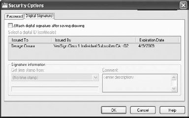
Click the Digital Signature tab (Figure 29.4).
Select the Attach Digital Signature After Saving Drawing option. The Signature Information options become available. You can add a date stamp and a brief description.
The next time you save the file, depending on the level of security you choose during the digital ID setup, you may be prompted for a password. After you enter the password, the file is saved.
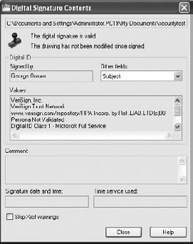
The next time the file is opened, you'll see the Digital Signature Contents dialog box (Figure 29.5), which verifies that no one has tampered with the drawing.
You'll also see a stamp icon in the lower-right corner of the AutoCAD window. You can click this icon at any time to view the file's digital signature status. You can also issue the Sigvalidate command to view the status. If the file is modified in any way and then saved, a warning message (Figure 29.6) will appear at the top of the Validate Digital Signatures dialog box the next time the file is opened.
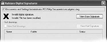
A file containing a digital signature also displays a warning when it's being modified, stating that saving a new version will invalidate the digital signature.
If you need to update a drawing that contains your digital signature, you can do so and then use the Security Options dialog box to reissue the digital signature.
If you have multiple files to which you'd like to attach your digital signature, you should use the Attach Digital Signatures utility. This program runs outside AutoCAD, and it provides a convenient way to attach your digital signature to a set of drawings. Here's how it works:

Click the Add Files button to locate and select files. You can also search for files in a particular folder by clicking the Search Folders button. The files you add appear in the Files To Be Signed list box.
If you decide to remove a file from the list box, highlight it and then click Remove. You can also remove all the files from the list by clicking Clear List.
The rest of the dialog box is the same as the Digital Signature tab of the Security Options dialog box. You can enter the date and time and a comment for the files you've selected.
Click Sign Files when you're sure you've selected the correct files and entered an appropriate comment.
If you exchange AutoCAD drawings regularly with clients and consultants, you'll want to obtain a digital ID and use AutoCAD's digital signature feature. Be aware, however, that because this feature was new in AutoCAD 2004, it works only if you exchange files with others using AutoCAD 2004 or later. In fact, a quick way to remove a digital signature from a file is to save the file in the AutoCAD 2002 or earlier file format.
If you intend to use the password feature in conjunction with your digital signature, you must add the signature first before adding the password.
The features discussed so far are intended mostly for exchanging files with others who need to work directly with your AutoCAD files. However, there are always associates and clients who need to see only your final drawings and don't care whether they get AutoCAD files. Alternatively, you might be working with people who don't have AutoCAD but still need to view and print your drawings. For those non-AutoCAD end users, AutoCAD offers the DWF file format.
You can think of the DWF file format as a kind of Adobe Acrobat file for AutoCAD drawings. DWF offers a way to get your plans and design ideas in the hands of more people more easily. With the help of the free Autodesk DWF Viewer—equivalent to the Adobe Reader for Acrobat documents—DWF files can be viewed using the same types of pan and zoom tools available in AutoCAD, which allows greater detail to be presented in your drawings. In addition, you can embed URL links that can open other documents with a single mouse click. These links can be attached to objects or areas in the drawing.
You can also print DWF files using your Windows system printer or plotter, all without having AutoCAD installed. A single DWF file can contain multiple drawing sheets, so you can combine a complete set of drawings into one DWF file. By default, AutoCAD saves DWF files in a new DWFx format that is compatible with the Windows Vista XPS format.
Imagine that you're working on a skylight addition to a house and you need to send your drawings to your client for review. In addition to the skylight plans, you want to include some alternate floor plans that your client has asked you to generate. In this exercise, you'll put together a set of drawings that will become a single DWF file that you'll send as an e-mail attachment to your client:
Open the
Sample house.dwgfile, which can be found in the Chapter 29 folder of the sample files. The file has several layout views, each representing a separate drawing sheet.Click the Save tool in the Quick Access toolbar. If you don't do this, the Publish tool you use later will ask you to do it anyway.
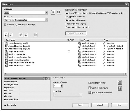
Choose Publish from the Application menu to open the Publish dialog box (Figure 29.8). You can also type Publish
In the list box, Ctrl+click Sample House-Model, Sample House-Foundation Details, and Sample House-Skylite Details to select them. Also Ctrl+click the three Unsaved Drawing items in the list. You don't want to include these layouts in your DWF file.

At this point, you could go ahead and create a DWF file. However, suppose you want to include layouts from a file that isn't currently open? The following steps show you how to accomplish this:

Locate and select the
sample house alt.dwgfile, which can be found in the Chapter 29 folder of the sample files. You see two new items, Sample House Alt-Model and Sample House Alt-Alternate Plan, in the list box. These are the layout views that are in thesample house alt.dwgfile.
All the sheets your client needs are listed in the list box. You're ready to create the DWF file:

Select a location and name for the sheet list and click Save.
Back in the Publish dialog box, in the Publish To drop-down list near the top of the dialog box, make sure the DWF option is selected. Notice that you can also select Plotter Named In Page Setup, DWFx, and PDF.
Turn off the Publish In Background option. By turning this feature off, you'll get your results faster.
Click the Publish button. The Specify DWF File dialog box appears. This is a standard file dialog box in which you can find a location for your DWF file and also name it. Select a name and location for the DWF file. By default, AutoCAD uses the same name as the current file and the folder location of the current file. You can also set up a default location in the Publish Setup dialog box.
Once AutoCAD is finished publishing your drawings, the Autodesk Design Review program opens the DWF file.
Go back to AutoCAD and click the Plot And Publish Details Report icon in the right side of the status bar. The Plot And Publish Details dialog box appears, offering detailed information about the sheets you published. You can then click the Copy To Clipboard button to export the list to a file as a record. If you want to recall this dialog box later, you can do so by choosing Print
You may notice that when you click the Publish button in the previous exercise, AutoCAD behaves as if it's printing the layouts in your list'and that is exactly what it's doing. AutoCAD uses its own DWF printer driver to "print" your drawings to a DWF file. AutoCAD uses the layout settings from the Plot dialog box for each layout to produce the DWF pages.
A few more options are available when you use the Publish feature. Let's take a moment to review some of the options in the Publish dialog box toolbar:
If you right-click an item or a set of items in the Publish dialog box list box, you see a menu with the standard options mentioned earlier plus some additional options. You'll want to know about a few of these options.
Viewing Dwf Files
The Autodesk Design Review program offers a fast and simple way to view DWF files, and as I mentioned earlier, it's free. It's installed automatically when you install AutoCAD. Choose Start
If the person receiving your DWF file doesn't have a copy of the Autodesk DWF Viewer, send them to the Products page of the Autodesk website (www.autodesk.com) to download their own copy. The download file is relatively small, and it is easily downloaded. If they are using Windows Vista, they won't need the viewer since the default DWF file format (DWFx) is XPS compatible. If you're using Windows Vista or Windows 7, your web browser may also be able to display DWF files.
By default, AutoCAD applies the existing layout settings for each layout when it produces the DWF file. These are the settings found in the Plot Or Page Setup dialog box and include settings such as the sheet size, scale, and page orientation. The Change Page Setup option lets you use a different set of layout settings for a selected layout in the list. To use this option, you must have saved a page setup in the file's Page Setup Or Plot dialog box. (See Chapter 8 for more on the Page Setup dialog box and its options.) You can import a page setup from a different AutoCAD file, or you can assign a page setup to a sheet. Do this by clicking the sheet name and selecting a page setup from the list box that appears in the Page Setup column.
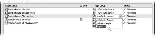
To change the page setup for multiple sheets, select the sheets from the list first and then select the setup from the list box.
If you happen to have two layouts with the same name, right-click a layout name, and then select the Rename Sheet option on the shortcut menu to rename a layout. The Copy Selected Sheets option adds copies of selected layouts to the list. The copies have the word copy appended to their names. The last two items in the shortcut menu let you control what is displayed in the list box. Include Layouts When Adding Sheets controls whether layouts are automatically imported from a drawing into the list box. Include Model When Adding Sheets controls whether Model Space views are automatically imported from a drawing into the list box.
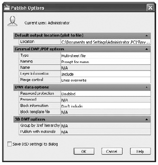
You can set up additional options by clicking the Publish Options button in the Publish dialog box. You'll then see the Publish Options dialog box (Figure 29.9).
This dialog box offers options for the location and type of output. The Default Output Location group lets you select the location for DWF files. The General DWF/PDF Options group lets you choose between a multi-sheet DWF file, which combines multiple sheets into one file, or single-sheet DWF files, which creates a file for each sheet. If you choose the multi-sheet option, you have the added option to specify a default name for your DWF files or to have AutoCAD prompt you for a name each time you create a DWF file. The DWF Data Options group lets you add password protection to the DWF file by using the Password option.
Another way to create DWF files is through the Plot dialog box. If you need to create a DWF file of only a single sheet, you may want to use the Plot dialog box because it's a simple and familiar procedure.
Open the file that you want to convert to DWF, and then proceed as if you're going to plot the drawing. In the Plot dialog box, select DWF6 ePlot.PC3 or DWFx ePlot (XPS Compatible).pc3 from the Name drop-down list in the Printer/Plotter area. The DWFx ePlot (XPS Compatible).pc3 option creates a file that is readable in Windows Vista without the need of any special viewing program.
Proceed with the plot the normal way. When AutoCAD would normally send the drawing to the printer, you'll see a dialog box asking you to enter a name for your plot file and finish with the rest of the plot. You can control the DWF plot as you would any plot.
In addition to using the settings available in the Plot dialog box, you can make some special configuration adjustments to the DWF plotter configuration file. Here is where to find those configuration settings:
Right-click the Quick View Layout tool in the status bar and select Page Setup Manager to open the Page Setup Manager dialog box, select a setup from the Page Setups list, and then click Modify to open the Page Setup dialog box.
Make sure the
DWF6ePlot.pc3configuration file is listed in the Name list box of the Printer/Plotter group.Click the Properties button to the right of the Name drop-down list to open the Plotter Configuration Editor dialog box.
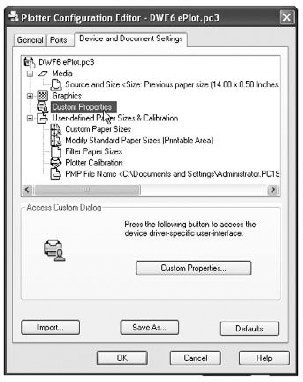
Make sure the Device And Document Settings tab is selected, and then click Custom Properties in the list box (Figure 29.10).
Click the Custom Properties button that appears in the lower half of the dialog box to open the DWF6 ePlot Properties dialog box. Here you can set the resolution, format, background color, and paper boundary for your DWF file. You can also specify whether to include layer and font information.
Click OK after selecting your settings. The Plotter Configuration Editor dialog box reappears. After you've set the custom properties, you can save any new settings in the
DWF6 ePlot.pc3file, or you can create a new DWF6 PC3 plot-configuration file. To save any setting changes, click the Save As button and select the PC3 file in which you want to save the settings. For more information about PC3 plot configuration files, see Fine-Tuning the Appearance of Output in Appendix C.Click OK in the Plotter Configuration Editor dialog box to return to the Page Setup dialog box.
Click OK to exit the Page Setup dialog box, and then close the Page Setup Manager.
After you select your custom configuration settings in step 5, you needn't open the Plotter Configuration Editor dialog box again the next time you plot a DWF file. If you save your new settings as a new PC3 file, you can select it from the File drop-down list in the Plotter Configuration group. You needn't reenter the custom settings.
You can either use the Publish feature described in the previous section to create single or multiple DWF files or create DWF files directly through the Plot dialog box. You can post the output from either method to a website to offer a wide distribution of your drawings. Just create a link to the DWF file from your web page. Be aware that the person attempting to view your DWF file from a web browser will need a copy of the free Autodesk DWF Viewer program that lets you view AutoCAD DWF files. The Autodesk DWF Viewer is automatically installed with AutoCAD 2010.
The Internet gave the world a tool that is so simple yet so powerful that it has permanently altered the way we look at information. Virtually every web page we view contains a hypertext link—a word, a sentence, or an image that takes us to another web page. Such links enable the viewer to explore the content of a website or gather more information on a particular topic.
AutoCAD offers a similar tool that you can apply to your AutoCAD drawings; it's called a hyperlink. With AutoCAD hyperlinks, you can link any document to an AutoCAD object. Then, with a few clicks of your mouse, you can follow the links to view other drawings, text files, spreadsheets, or web pages. After you create a hyperlink in an AutoCAD drawing, you can export the drawing to a DWF file and that DWF file will also contain the same links. You can then post that DWF file on a web page where others can gain access to those links.
The inclusion of hyperlinks in drawings and DWF files opens a world of new possibilities in the way you work with drawings. You can link product specifications directly to the objects in the drawing that represent the product. You can also link to extended data beyond the simple symbol or graphic in a drawing, such as to a database table or a spreadsheet.
You don't have to limit your links to HTML files containing AutoCAD drawings. You can link to all sorts of web documents, to drawings on your computer or your company network, and even to documents on other sites.
The following shows you how to add links to a sample floor plan:
In AutoCAD, open the file
Houseplan.dwg.
At the
Select objects:prompt, click on the hexagonal door symbol, as shown in Figure 29.11.When you're done, press
Click the File button on the right side of the dialog box to open the Browse The Web – Select Hyperlink dialog box. It's a typical file dialog box.
Locate the
doorsch.dwffile in theProjectssubfolder and select it.Click Open. The Insert Hyperlink dialog box reappears. Notice that
doorsch.dwfappears in the list box at the top of the dialog box.Make sure the Use Relative Path For Hyperlink option isn't selected, and then click OK.


The link you just created is stored with the drawing file. You can create a DWF file from this drawing and the link will be preserved in the DWF file.
Now let's see how you can use the link from within the AutoCAD file:
Move your cursor over the hexagonal door symbol. Notice that the cursor changes to the hyperlink icon when it's placed on the symbol. It also shows the name of the file to which the object is linked. This tells you that the object is linked to another document somewhere on your system, on your network, or on the World Wide Web (Figure 29.13).
Click the hexagonal door symbol to select it.
Right-click a blank area of the drawing. In the shortcut menu, choose Hyperlink

The Autodesk Design Review program opens and displays the file doorsch.dwf file. If you installed the sample figures on another drive or folder location, the Hyperlink menu option will reflect that location
You've used the doorsch.dwf file as an example in these exercises, but this could have been a text file, a spreadsheet, a database, or even another AutoCAD file. AutoCAD will start the application associated with the linked file and open the file.
You can edit or delete a hyperlink by doing the following:
Right-click the object whose link you want to edit, and then choose Hyperlink
You can now change the link, or you can click the Remove Link button in the lower-left corner of the dialog box to delete the link.
You were introduced to the Insert Hyperlink dialog box, shown in Figure 29.12, in the previous exercises. Let's take a moment to study this dialog box in a little more detail.
To specify a file or a website to link to, you can enter either a filename or a website URL in the Type The File Or Web Page Name input box or use the Or Select From List area, which offers a list box and three button options. When you select one of the buttons, the list box changes to offer additional related options:
- Recent Files
Displays a list of recently edited AutoCAD files, as illustrated in Figure 29.12. You can then link the object to a file in the list by clicking the filename.
- Browsed Pages
Displays a list of websites that you recently visited using your web browser.
- Inserted Links
Displays a list of recently in serted links, including files or websites.
You can also use the three buttons to the right of the list box to locate specific files (the File button), websites (the Web Page button), or saved views (the Target button) in the current drawing.
As you saw in the exercise, the File button opens the Browse The Web dialog box, which lets you locate and select a file from your computer, from your local area network, or even from an FTP site. This is a typical AutoCAD file dialog box with some additional features.
The Web Page button on the right opens a simplified web browser that lets you locate a web page for linking (as shown earlier, in Figure 29.12). In this dialog box, you can use the standard methods for accessing web pages, such as using the Look In drop-down list to select recently visited pages or entering a URL in the Name Or URL input box. The page is then displayed in the main window of the dialog box.
The Target button in the Insert Hyperlink dialog box opens the Select Place In Document dialog box, which lists the saved views in the drawing that is selected in the Edit Hyperlink list box.
Views are subdivided by Layout tab. At the top is the Model Space tab listing, and below that are other Layout tab listings. If the current drawing contains saved views, you see a plus sign next to the Layout tab name. Click the plus sign to display a listing of the views in that layout.
At the top of the Insert Hyperlink and Edit Hyperlink dialog boxes is an input box labeled Text To Display. When a hyperlink is added to an object in AutoCAD, AutoCAD will display a hyperlink icon whenever the cursor passes over the object. You can also include descriptive text that will display along with the icon by entering a description in the Text To Display input box.

By default, the text is the name of the hyperlinked item that you select. You can change the text to provide a better description of the link.
There is a column of options at far left in the Insert Hyperlink dialog box, labeled Link To. The top button, Existing File Or Web Page, displays the options discussed so far in this section. The other two buttons change the appearance of the Insert Hyperlink dialog box to offer different but familiar options:
- View Of This Drawing
This button changes the display to show just the views that are available in the current drawing. This option performs the same function as the Target button described earlier.
- E-Mail Address
This button changes the Insert Hyperlink dialog box to enable you to link an e-mail address to an object. Clicking the object will then open your default e-mail application, enabling you to send a message to the address.
As you start to build a library of drawings, you'll find that you reuse many components of existing drawing files. Most of the time, you'll probably be producing similar types of drawings with some variation, so you'll reuse drawing components such as layer settings, dimension styles, and layouts. It can be a major task to keep track of all the projects you've worked on. It's especially frustrating when you remember setting up a past drawing in a way that you know would be useful in a current project but you can't remember that file's name or location.
AutoCAD offers DesignCenter to help you keep track of the documents you use in your projects. You can think of DesignCenter as a kind of super Windows Explorer that is focused on AutoCAD files. DesignCenter lets you keep track of your favorite files and helps you locate files, blocks, and other drawing components. In addition, you can import blocks and other drawing components from one drawing to another by using a simple click and drag. If you've been diligent about setting a unit format for each of your drawings, you can use DesignCenter to import symbols and drawings of different unit formats into a drawing, and the symbols will maintain their proper size. For example, a 90 cm door symbol from a metric drawing can be imported into a drawing in Imperial units and the DesignCenter will translate the 90 cm metric door size to a 35.43″ door.
At first glance, DesignCenter looks a bit mysterious. But it takes only a few mouse clicks to reveal a tool that looks much like Windows Explorer. Try the following steps to get familiar with DesignCenter:

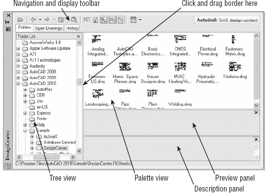
DesignCenter opens as a floating palette (see Figure 29.14).

DesignCenter displays a listing of the
Favoritesfolder. You're actually looking at a view into theC:Documents and SettingsUsernameFavoritesAutodeskfolder, whereUsernameis your login name. Unless you've already added items to theFavoritesAutodeskfolder, you see a blank view in the right panel. You can add shortcuts to this folder as you work with DesignCenter. You may also see a view showing the tree structure of the files you have open in AutoCAD.

Place your cursor in the lower-right corner of the DesignCenter window so that a double-headed diagonal arrow shows. Then click and drag the corner out so you have an enlarged DesignCenter window that looks similar to Figure 29.15. The view on the right, containing the
DesignCenterfolder, is called the Palette view. The view on the left is called the Tree view.Place your cursor on the border between the Tree view and the Palette view until you see a double-headed cursor. Then click and drag the border to the right to enlarge the Tree view until it covers about one-third of the window.
Use the scroll bar at the bottom to adjust your view of the Tree view so you can easily read its contents.
After you have it set up like this, you can see the similarities between DesignCenter and Windows Explorer. You can navigate your computer or network by using the Tree view, just as you would navigate Windows Explorer. There are a few differences, however, as you'll see in the following exercise:

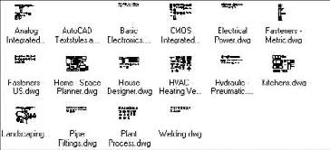
Instead of the usual list of files, you see a sample image of each file. These are called preview icons.

Click the Views tool again, and choose Large Icons to return to the previous view. The Views tool is similar to the various View options in Windows Explorer.
Click the
Basic Electronics.dwgfile to select it. You see a preview of the selected file in the Preview panel of DesignCenter. You can adjust the vertical size of the Preview panel by clicking and dragging its top or bottom border.
Below the Preview panel is the Description panel. This panel displays any text information included with the drawing or drawing element selected in the Palette view. To add a description to a drawing that will be visible here, choose Drawing Utilities
Both the Preview and the Description panels can offer help in identifying files that you may be looking for. After you find a file, you can click and drag it into a folder in the Tree view to organize your files into separate folders.
You can also add files to the Favorites folder by right-clicking and then choosing Add To Favorites. The file itself isn't moved to the Favorites folder; instead, a shortcut to the file is created in the Favorites folder. If you want to work on organizing your Favorites folder, you can open a window to the Favorites folder by right-clicking a file in the Palette view and choosing Organize Favorites. A window to the Favorites folder appears.
Because you'll be working with the sample drawings, go ahead and add the Projects folder to the Favorites folder:
Locate the
Projectsfolder (the one created when you installed the sample files) in the left panel Tree view, and right-click it.Choose Add To Favorites from the shortcut menu.

Double-click the Projects shortcut in the Palette view. You see the contents of the
Projectsfolder.
You can go beyond just looking at file listings. You can look inside files to view their components:
In the Palette view, locate the file named
16-unit.dwgin the Chapter 16 folder, and double-click it. You see a listing of its components in the Palette view. The Tree view also shows the file highlighted.Double-click the Block listing in the Palette view. Now you see a listing of all the blocks in
16-unit.dwg
What Is Autodesk Seek?
You might notice the Autodesk Seek banner in the upper-right corner of the DesignCenter palette. If you click this banner, your web browser opens to the Autodesk Seek home page where you will find a rich resource for drawings and models from manufacturers and users. 2D and 3D files are available in a number of formats, including DWG, DWF, and PDF. You can even share your own drawings with other users using the Output tab's Autodesk Seek panel. There are numerous other ways to share your own content. For example, you can find type Sharewithseek
From here, you can import any of the drawing components from the DesignCenter palette into an open drawing in AutoCAD. But before you try that, try a few other features of the DesignCenter.
By using DesignCenter, you can more easily locate the files you're looking for because you can view thumbnail preview icons. But often that isn't enough. For example, you might want to locate all the files that contain the name of a particular manufacturer in an attribute of a drawing.
After you've found the file you're looking for, you can load it into AutoCAD by right-clicking the filename in the Palette view and then choosing Open In Window. Try it with the following exercise:

In the Tree view, select the Chapter 12 folder. Then, in the Palette view of DesignCenter, locate the
12c-unit.dwgsample.Right-click the
12c-unit.dwgfile and select Open In Application Window. The drawing appears in the AutoCAD window.
If you want to insert a file into another drawing as a block, you can do so by clicking and dragging the file from the DesignCenter Palette view into an open drawing window. You can also right-click and select Insert As Block. You're then prompted for the insertion point, scale, and rotation angle. If you prefer to use the Insert dialog box to insert a drawing from DesignCenter, right-click the filename in the Palette view and then choose Insert As Block. The Insert dialog box opens, offering you the full set of Insert options, as described in Chapter 4.
Finally, you can attach a drawing as an Xref by right-clicking a file in the Palette view of DesignCenter and choosing Attach As Xref. The Attach External Reference dialog box opens, offering the insertion point, scale, and rotation options similar to the options in the Insert dialog box. This is the same dialog box described in Chapter 7.
Aside from the convenience of being able to see thumbnail views of your drawing, DesignCenter may not seem like much of an improvement over Windows Explorer. But DesignCenter goes beyond Windows Explorer in many ways. One of the main features of DesignCenter is that it enables you to locate and extract components of a drawing.
Imagine that you want to find a specific block in a drawing. You remember the name of the block, but you don't remember the drawing you put it in. You can search the contents of drawings by using DesignCenter's Search dialog box. In the following exercise, you'll search for a block named Kitchen2-metric among a set of files.

Select the drive that contains your
Projectsfolder from the In drop-down list.Select Blocks from the Look For drop-down list. As you can see from the list, you can look for a variety of drawing component types (Figure 29.17).
Enter Kitchen2-metric
Double-click the block name. DesignCenter displays the block in the Palette view and the file that contains the block in the Tree view.

As you saw from the previous example, the Search dialog box can be helpful in finding items that are buried in a set of drawings. In the exercise, you searched for a block, but you can search for any named drawing component, including attribute data and text. For example, if you want to find all attributes that contain the name ABC Manufacturing Company in your drawings, you can do so with the DesignCenter Search dialog box. Table 29.2 shows a summary of its features. When you select Drawings from the Look For drop-down list, you see a set of additional tabs in the Search dialog box, as described in Table 29.3.
Table 29.2. DesignCenter Search Dialog Box Options
Option | Purpose |
|---|---|
In | Lets you select the drive you want to search. |
Look For Options | Lets you select the type of item to search for. The options are Blocks, Dimstyles, Drawings, Drawings And Blocks, Hatch Pattern Files, Hatch Patterns, Layers, Layouts, Linetypes, Multileaderstyles, Tablestyles, Textstyles, and Xrefs. |
Browse | Lets you locate a specific folder to search. |
Search Subfolders | Lets you determine whether Search searches subfolders in the drive and folder you specify. |
Search Now | Starts the search process. |
Stop | Cancels the current search. |
New Search | Clears all the settings for the current search so you can start fresh on a new search. |
Help | Opens the AutoCAD help system to the Search topic. |
Table 29.3. DesignCenter Search Dialog Box Tab Options When Drawings Is Selected from the Look For Drop-Down List
After you've found a block by using DesignCenter, you can click and drag the block into your open drawing. In the following exercise, you'll do that, but with a slight twist. The block you've found is drawn in centimeters, but you'll insert the Kitchen2-metric block into a drawing named 12c-unit.dwg, which was created in the Imperial measurement system. If you were to insert the Kitchen2-metric block into 12c-unit.dwg, the kitchen would be exactly 2.54 times larger than it should be for 12c-unit.dwg. But as you'll see, DesignCenter takes care of scaling for you. Follow these steps:
If you haven't done so already, load the
12c-unit.dwgsample drawing in AutoCAD. You can temporarily close DesignCenter to do this.Back in DesignCenter, click and drag the Kitchen2-metric block from the Palette view into the
12c-unit.dwgwindow in AutoCAD. The kitchen appears at the appropriate scale.To see that DesignCenter did indeed adjust the scale of the Kitchen2-metric block, click it in the 12c-unit window, and then right-click and choose Properties.
Check the Scale X, Scale Y, and Scale Z settings in the Geometry category. Notice that they show .3937 as the scale factor instead of 1.
After reviewing the Properties palette, close it.
You may recall from Chapter 3 that you have the opportunity to specify the type of units the drawing is set up for in the Drawing Units dialog box under the Insertion Scale group. DesignCenter uses this information when you drag and drop blocks from DesignCenter into an open drawing. This is how DesignCenter is able to scale a block drawn in metric to a drawing that is drawn in the Imperial format correctly. The same option is offered in the Block Definition dialog box.
Blocks aren't the only type of drawing component you can click and drag from the Palette view. Linetypes, layouts, dimension styles, and text styles can all be imported from files on your computer or network through DesignCenter's Palette view.
You've seen how you can extract a block from a file stored on your hard disk and place it into an open drawing, but what if you want to copy a block from one open drawing to another open drawing? You change the way the Tree view displays data so that it shows only the files that are loaded in AutoCAD. The following exercise demonstrates how this works:
In AutoCAD, make sure that
12c-unit.dwgis still open, and then open the12c-unit-metric.dwgfile.In DesignCenter, click the Open Drawings tab above the Tree view. The Tree view changes to display only the drawings that are open.
Click the plus sign (+) to the left of the
12c-unit.dwgfilename in the Tree view. The list expands to show the components in12c-unit.dwg.Click Blocks in the Tree view. The Palette view changes to show a list of blocks available in
12c-unit.dwg.Locate the Kitchen block in the Palette view.
Click and drag Kitchen from the Palette view into the open
12c-unit-metric.dwgdrawing in AutoCAD. The block moves with the cursor. Once again, DesignCenter has automatically scaled the block to the appropriate size, this time from Imperial to metric.Click anywhere in the drawing to place the Kitchen block.
In this example, you inserted a block from one open drawing into another drawing. If you prefer to use the Insert dialog box, you can right-click the block name in step 6 and choose Insert Block. The Insert dialog box opens, enabling you to set the insertion point, scale, and rotation options.
Just as with drawings, you can see a preview and descriptive text for blocks below the Palette view. In Chapter 4, you had the option to save a preview image with the block when you first created a block. This is where that preview icon can be really helpful. The preview icon gives you a chance to see what the block looks like when you use DesignCenter to browse through your drawing files. If you don't save a preview icon, you'll see the same block icon that was displayed in the previous Palette view.
You can also add the text description at the time you create the block. Before saving the block, enter a description in the Description input box of the Block Definition dialog box.
If you're updating older drawing files to be used with DesignCenter, you can add text descriptions to blocks by using the Create tool in the Home tab's Block panel or the Create tool in the Blocks & References tab's Block panel. Click the Create tool and then, in the Block Definition dialog box, select the name of a block from the Name drop-down list. Enter the description you want for this block in the Description input box toward the bottom of the Block Definition dialog box. When you're finished, click OK.
If you want to open a file in DesignCenter that you've recently opened, you can use the History tab just above the Tree view. The Tree view closes and you see a list of the files you've worked on most recently.
In addition to obtaining files and blocks from your computer or network, you can download symbols directly from Autodesk's DesignCenter Online website. This option offers thousands of ready-to-use symbols for a variety of disciplines. Follow these steps:
Connect to the Internet.
Click the DC Online tab that appears above the Tree view. The DesignCenter Online symbol categories appear in the Tree view, and the Palette view shows the same categories in a text view.
Expand the 2D Architectural listing in the panel to the left to display a set of subcategories.
Expand the Bathrooms category, and then click Bath Tubs. The Palette view displays a set of bathtubs.
Click one of the bathtubs. The i-drop icon appears.
Click a tub to display an enlarged preview of it in the display panel along with a description of the symbol.
Click and drag a symbol into the current open drawing. The i-drop cursor appears in the drawing. When you release the mouse button, the symbol appears at the cursor, waiting for you to select an insertion point.
Click a location to place the symbol.
To return to the opening page of DesignCenter Online, click the DesignCenter Online item at the top of the Tree view.
Because DesignCenter Online is a website, AutoCAD uses the i-drop feature to bring the symbols into your drawing. As you can see, the list of symbols is fairly extensive. Many of the symbols are samples from third-party vendors that offer expanded symbols libraries.
Many AutoCAD users have built their own custom library of symbols and are accustomed to using them in conjunction with custom menus. But creating and editing menus is a bit cumbersome and can become difficult to manage. In Chapter 1, you saw how easy it is to drag and drop a symbol, known as a tool, from the Tool palettes. At first glance, there is no obvious way to add your own tools to the palettes. Adding tools and additional palettes to the Tool palettes is fairly simple once you're familiar with DesignCenter. The following exercise shows you how it's done:

Right-click in the Tool palettes, and then choose New Palette from the shortcut menu.
Enter My Tool Palette

In the Palette view to the right, double-click the
Landscaping.dwgfile, and then double-click the Blocks icon that appears in the Palette view.Make sure that the Tool palettes are visible behind DesignCenter, and then Ctrl+click Clump Of Trees Or Bushes ' Plan and North Arrow.
Click and drag the selection to the Tool palettes.
You've just created a Tool palette and added two symbols. You can continue to add symbols from other drawings to your custom Tool palette. Or, if you have a drawing that contains all the blocks you need for a Tool palette, you can quickly create a Tool palette directly from a file. Here's how that's done.

Right-click
Landscaping.dwg, and then choose Create Tool Palette. After a few moments, a new Tool palette called Landscaping appears in the Tool palettes. This new palette contains all the blocks found in theLandscaping.dwgfile.
This exercise showed that you can quickly create a palette of all the blocks from a file. You can do the same thing with entire folders of drawings, although you may want to make sure such folders don't contain too many files.
But what if you don't want some of the items in your custom palette? You can remove items easily by using a shortcut menu:
In the Landscaping palette, select the top three symbols by right-clicking the tool that is third from the top and then Shift+clicking the top tool. This is a little different from the typical Windows method for selecting items from a list.
Right-click and choose Delete from the shortcut menu. Click OK to confirm the deletion.
You may have noticed the Cut and Copy options in the shortcut menu in step 2. You can use these options to move symbols from one palette to another. For example, instead of deleting the three symbols in step 2, you can choose Cut from the shortcut menu, open another palette, right-click, and choose Paste. The symbols move to the new palette location. In the next section, you'll see how you can use the Copy and Paste shortcut menu options to make a copy of a tool in the same palette.
Other shortcut menu options let you delete entire palettes or rename tools or palettes. You can also edit the properties of symbols in a palette. The following exercise shows how to use the shortcut menu options to create two scale versions of the same tool:
In the Landscaping tab of the Tool palettes, right-click the North Arrow tool, and choose Copy from the shortcut menu.
Right-click a blank area of the palette and choose Paste. A copy of the North Arrow tool appears in the palette.
Right-click the copy of the North Arrow tool, choose Rename from the shortcut menu, and then enter North Arrow Copy.
Right-click the North Arrow Copy tool, and choose Properties to open the Tool Properties dialog box (Figure 29.18).
Click 1.0000 to the right of the Scale listing, and change the value to 4.
Click OK, and then click and drag the North Arrow Copy tool into the drawing.
Click and drag the original North Arrow tool into the drawing. Notice that the original North Arrow is smaller than the North Arrow Copy, whose scale you changed to 4.

This exercise demonstrated that you can have multiple versions of a tool at different scales. You can then use the tool that's appropriate to the scale of your drawing. As you can see from the Tool Properties dialog box, you can modify other tool properties, such as color and layer assignments. You can use this feature to create sets of tools for different scale drawings. For example, you can create a palette of architectural reference symbols for ¼″-scale drawings, and you can create another palette for ⅛″-scale drawings.
You've seen how you can turn blocks into Tool palette tools, but what about solid fills? In Chapter 1, you saw that sample hatch patterns and solid fills are available in the Tool palettes. Here's how you can add your own:
In DesignCenter, use the Tree view to locate the
AutoCAD 2010 Supportfolder. In Windows XP or Vista, it's typically inC:Documents and SettingsUsernameApplication DataAutodesk AutoCAD 2010R18.0enuSupport(UserNameis your Windows login name).
Double-click the
acad.patfile shown in the Palette view. AutoCAD builds a list of the patterns and displays the list in the Palette view.You can now click and drag a pattern into any Tool palette. You can also click and drag an entire PAT file into the Tool palette to create a palette of all the patterns in a hatch pattern file.
In this exercise, you used the standard hatch patterns that come with AutoCAD. You can also create your own custom hatch patterns and import them to the Tool palettes by using the method described here. See Chapter 26 for more information on creating custom hatch patterns.
If you want to set up a set of solid fill colors, you can do the following:
Click and drag the solid fill pattern from the
Acad.patfile into the Tool palette.Right-click the new solid fill tool, choose Properties from the shortcut menu, and select a color from the Color drop-down list in the Tool Properties dialog box.
You can select any color, including colors from the True Color or Color Book tab in the Select Color dialog box that you learned about in Chapter 5. You can also cut and paste an existing solid fill tool to make copies. You can then modify the color property for each copy to get a set of custom solid fill colors.
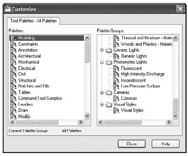
You can perform other types of Tool palette maintenance operations by using the Customize dialog box. For example, you can change the order of the Tool palette tabs, or you can group tabs into categories that can be turned on or off. The following steps offer a glimpse of what you can do by showing you how to group palettes:
To open the Customize dialog box (Figure 29.19), right-click the Tool palettes, and choose Customize Palettes from the shortcut menu.
Right-click in a blank area of the Palette Groups panel, and choose New Group.
Enter My Group for the new group name.
Click and drag My Group to a position just above another group so that it's its own group instead of a subgroup.
Click and drag Landscaping from the left panel to the right panel just below My Group. A black bar appears below My Group. Release the mouse button.
Click and drag My Tool Palette from the left panel to the right, just below Landscaping.
You've just created a new palette group and moved the two new palettes. You can view the palettes separately or all together:
Click Close to close the Customize dialog box. The Tool palette still displays all the tabs.
To display only the new tabs, click the Properties button at the bottom of the palette.
Select My Group. Now the Tool palette shows only the two tabs you just created.
You may have noticed that in the Properties menu, you also have the option to show just the new groups or all the palettes. This feature lets you keep the tabs in the Tool palettes organized.
The list on the left side of the Customize dialog box also lets you change the order of the tabs by clicking and dragging the tab names up or down in the left panel. If you select a palette in the left panel and right-click, you can rename, delete, import, or export a palette.
DesignCenter and Tool palettes offer great features that will prove invaluable to AutoCAD users. Although these examples show you how to use DesignCenter on a stand-alone computer, you can just as easily perform the same functions across a network or even across the Internet.
This ends our exploration of DesignCenter and Tool palettes. In the next part of this chapter, you'll look at AutoCAD's tools for maintaining layer naming and other standards throughout an organization and for converting between your own layering system and those of clients or partners.
Communication is especially important when you're one of many people working on the same project on separate computers. A well-developed set of standards and procedures helps to minimize problems that may be caused by miscommunication. In this section, you'll find some suggestions for setting up these standards.
The issue of CAD standards has always been difficult to resolve. Standardizing layers, dimensions, and text can go a long way toward making file exchange more seamless between different trades, and standards can also make files easier to understand. When everyone follows a standard, the structure of a drawing is more easily understood, and those who have to edit or interpret your work can do so without having to ask a lot of questions.
You've seen how layers can be a useful tool. But they can easily get out of hand when you have free rein over their creation and naming. With an appropriate layer-naming convention, you can minimize this type of problem (although you may not eliminate it entirely). A too-rigid naming convention can cause as many problems as no convention at all, so it's best to give general guidelines rather than force everyone to stay within narrow limits. As mentioned in Chapter 5, you can create layer names in a way that enables you to group them by using wildcards. AutoCAD allows up to 31 characters in a layer name, so you can use descriptive names.
Lineweights should be standardized in conjunction with colors. If you intend to use a service bureau for your plotting, check with them first; they may require that you conform to their color and lineweight standards.
The Standards command lets you quickly compare a drawing against a set of standard layer names, dimension style settings, linetypes, and text styles. A dialog box displays any item that doesn't conform to the standards you selected. You can then adjust the file to make it conform to your standards.
You can create several sets of standards for different types of files, and you can assign the standards directly to a file so that anyone editing that file can make periodic checks against your office standards while the drawing is being edited.
The first step in using the Standards command is to set up a file to which other drawing files can be compared. Standards uses an AutoCAD drawing file with a .dws filename extension. Here are the steps to create a new DWS standards file:
Open AutoCAD, and click New from the Quick Access toolbar to create a new file.
Set up the file with the layers, linetypes, dimension styles, and text styles you want as your standards.
Choose Save As from the Application menu.
In the Save Drawing As dialog box, choose AutoCAD Drawing Standards (*.dws) from the Files Of Type drop-down list.
Choose a convenient folder for the location of your standards file, and click Save.
As an alternative to creating a new file, you can open an existing file that contains all the typical settings you'll want to use on your projects. You can then delete all the graphics in the file and purge all its blocks and shapes. After you've done this, you can begin at step 3 of the previous exercise to save the file as a DWS standards file.
You can set up as many DWS files as you need for your office. Often, a single set of standards is too limiting if your office is involved in a diverse range of projects, so you may want to set up DWS files on a project basis, drawing on a core of generic DWS files.
After you've created your DWS standards files, you can begin to check other files for conformity. The next task is to assign your DWS file to the drawing file that you want to check:
In AutoCAD, open the file you want to check for standards conformity.
Click Configure on the Manage tab's CAD Standards panel to open the Configure Standards dialog box. This dialog box contains a list box and a description area. A row of buttons appears vertically between the list box and description.

The Select Standards File dialog box opens. This is a typical AutoCAD file dialog box. Notice that the Files Of Type drop-down list shows the Standards (*.dws) file type.
Locate and select the standards file that you want to use to check the current file. After a moment, the name of the file you select appears in the list box of the Configure Standards dialog box (Figure 29.20). On the right side of the dialog box, you see a description of the standards file.
Check the current file against the DWS standards file. Click the Check Standards button in the lower-left corner of the Configure Standards dialog box. AutoCAD pauses while it checks the current file, and then you see the Check Standards dialog box.

If AutoCAD finds a discrepancy between the standards file and the current file, a description of the problem appears at the top of the dialog box. For example, if a dimension style name that isn't in the standards file appears in the current file, a message appears indicating that a nonstandard dimension style name exists in the current drawing. If this happens, take the following steps:
Below the problem statement is the Replace With list box, which contains options related to the nonstandard item. You can replace the nonstandard item in your file with an option in the Replace With list box by selecting the option and clicking the check box to the right of the list. Or you can leave the problem alone for now.
Click the Next button in the bottom-right corner of the Check Standards dialog box to move to the next problem.
Repeat steps 1 and 2 until you see the statement
Checking is completein the Problem list box and the Checking Complete dialog box opens to display a summary of the checking results.
In this example, you entered the Check Standards dialog box directly from the Configure Standards dialog box. After you've used the Check Standards dialog box on a file, the DWS standards file is associated with the checked file. You can go directly to the Check Standards dialog box by choosing Tools
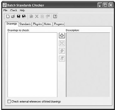
The Standards and Check Standards commands are great for checking individual files, but eventually you'll want a method to batch-check a set of files. AutoCAD 2010 provides a utility that does just that. The Batch Standards Checker is a stand-alone utility that audits a set of drawing files and checks them against their associated DWS files. The Batch Standards Checker can also check a set of drawings against a single DWS file of your choice. It then generates an audit report showing any problems it encounters.
Here's how it works:
From the Windows Desktop, choose Start
Click the Plus button in the middle of the dialog box to open the Batch Standards Checker – File Open dialog box. This is a typical AutoCAD file dialog box.
Locate and select the drawings you want to check. You return to the Batch Standards Checker dialog box, and after a moment, a list of the drawings you selected appears in the Drawings To Check list box.
Click the Standards tab (Figure 29.22). This is where you can select the standards file against which your selection will be checked.
If the drawings you selected in step 3 already have a standards file associated with them, you can use the Check Each Drawing Using Its Associated Standards Files option to check each file. You can then skip to step 7.
If you select the Check All Drawings Using The Following Standards Files option, click the plus sign in the middle of the dialog box to open the file dialog box.
Locate and select a DWS standards file. The file then appears in the Standards Used For Checking All Drawings list box on the left of the Standards tab in the Batch Standards Checker dialog box.
Click the Save button at the top of the Batch Standards Checker dialog box.
The Batch Standards Checker file dialog box opens to enable you to specify a standards check file name and location. This file has a
.chxfilename extension.

When the checking is finished, the data from the audit is automatically saved in the check file you created in step 7. Then the audit file is opened in your web browser and you see the results of the audit.
The audit report file displays a number of options in a set of radio buttons:
- Overview
Displays a simplified view of the problems encountered by the audit. It lists the drawings audited and the number of problems encountered.
- Plug-Ins
Shows the standard plug-ins used to audit the drawings. Autodesk supplies these standard plug-ins, which test for layers, dimension styles, linetypes, and text styles. Third-party developers can create other plug-ins to check for additional problems.
- Standards
Lists the DWS standards files used for the audit.
- Problems
Displays a detailed description of the problems encountered in the audit. It gives the drawing name and the specific item name that is a problem. For example, if the audit discovers a nonstandard layer name, the layer name is listed under the drawing name as a nonstandard layer.
- Ignored Problems
Displays problems that have previously been flagged as problems to ignore. You can flag problems to be ignored by using the Check Standards command in AutoCAD. (See the section "Using the Standards Command to Associate Standards" earlier in this chapter.)
- All
Displays all the audit information.
This opens the Batch Standards Checker file dialog box, where you can locate and open a previously saved standards check file with the .chx filename extension. In this file, you see a list of the files that were checked in the Drawings tab and the DWS standards file used in the Standards tab.
You can then view the results of the audit by clicking the View Report tool in the toolbar. This opens a web browser and displays the audit results contained in the standards check file.
As AutoCAD files flow in and out of your office, you're likely to find yourself working with layering standards from another system. You might, for example, receive files from an architect who uses the CSI standard for layer names, whereas your office prefers the AIA standard. If your job involves extensive reworking of such files, you'll want to change the layering system to one you're most familiar with. But converting layer settings is a painstaking and time-consuming process, especially if several files need conversion.
Fortunately, AutoCAD offers a tool that can make layer conversion from one standard to another much easier. The Layer Translator lets you map nonstandard layers (that is, those using a system different from your own) to your own set of standard layers. It can then convert those layers to match your office standards. After you've mapped a set of layers between two files, you can save the map settings in a drawing file. Then any other files you receive that contain the same nonstandard layer settings can be converted to your own layer standards quickly. Let's take a closer look at how the Layer Translator works.
When using the Layer Translator, you must initially match the layers of your incoming file with those of a file whose layers are set up the way you want. Here are the steps to do this:
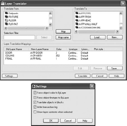
Open the file whose layers you want to convert in AutoCAD. Click the Layer Translator tool from the Manage tab's CAD Standards panel to open the Layer Translator dialog box, which lists the layers from the current file in the Translate From list box.
Click the Load button in the Translate To group to open the Select Drawing File dialog box. Locate and select a file that contains the layer settings you want to use for this project. The file can be a standard DWG file, or it can be a DWS standards file or a DWT template file. After you've opened a file, its layer names appear in the Translate To list box.
Select a layer name in the Translate From list, and then select the layer you want to convert it to from the Translate To list box. After you've made your two selections, click the Map button in the middle of the dialog box. An item in the Layer Translation Mappings group shows you the old and new layer names and the layer settings for the conversion (see Figure 29.23).
Repeat step 3 for all the layers you want to convert. You can map several layers from the Translate From list to a single layer in the Translate To list if you need to.
If there are matching layers in the Translate From and Translate To list boxes, the Map Same button in the middle of the dialog box becomes active. You can then click this button to automatically map layers that have the same names in both the Translate From and the Translate To lists.

After you've completed your layer mapping, you can save the mapping for future use:
While still in the Layer Translator dialog box, click the Save button in the Layer Translation Mappings group to open the Save Layer Mappings dialog box. This is a typical AutoCAD file dialog box.
Enter a name for your saved settings and click Save. You can save the layer-map settings as either a DWS standards file or a DWG file.
Click the Translate button and AutoCAD will proceed to translate the mapped layers.
After you've saved the layer mapping in step 2, you can load the saved layer-map settings into the Layer Translator dialog box in future layer translations. This saves you the effort of mapping each layer individually each time you want to perform a translation. This will work for incoming files that use the same layer settings, but you'll have to create another layer-map settings file for each different layer system you encounter.
To use a saved layer map, click the Load button in the Translate To group of the Layer Translator dialog box, and then select the layer-map file you saved in step 2. You can have several layer-map files for each project involving files with nonstandard layer settings.
You'll often come across situations in which the layers in the Translate From list don't correspond directly to those in the Translate To list. For these situations, the Layer Translator offers a few additional options.
If you have difficulty finding a match for layers in the Translate From list, you can create a new layer by clicking the New button in the Translate To group. This opens the New Layer dialog box (Figure 29.24), in which you can enter the properties for your new layer.
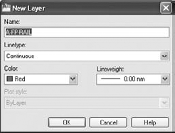
After you create a new layer with this dialog box, it appears in the Translate To list box, enabling you to map Translate From layers to your new layer.
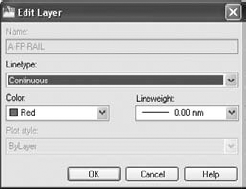
Another option you'll find useful is the Edit button in the Layer Translation Mappings group. You may find that after you've mapped a Translate From layer to a Translate To layer, the Translate To layer isn't exactly what you want. You can highlight the mapped layer in the Layer Translation Mappings group list box and then click Edit to open the Edit Layer dialog box (Figure 29.25). From here, you can modify the new layer's settings from their original values.
Finally, the Layer Translator (Figure 29.23) offers a set of options that give you some control over the way translations are performed. For example, you can control whether layer colors and linetypes are forced to the ByLayer setting or whether layer assignments for objects in blocks are translated. You can access these options by clicking the Settings button in the lower-left corner of the Layer Translator dialog box. Figure 29.26Figure 29.26 shows the Settings dialog box. The options are self-explanatory.
- Share drawings over the Internet
As a drafter or designer, it's very likely that you'll be involved in collaborative efforts, which means you'll have to share your work with others. The Internet has made it much easier to do this.
- Master It
Why is eTransmit important for sending AutoCAD drawings over the Internet?
- ePublish your drawings
Autodesk offers the DWF drawing format, which lets non-CAD users view and add comments to your drawings. You can use the Publish feature to create a single DWF file from several drawings.
- Master It
True or false: The Publish feature can be used to plot multiple drawings in the background.
- Manage your drawings with DesignCenter and the Tool palettes
The DesignCenter is a great tool for managing your drawings' resources, like blocks, custom linetypes, and other elements.
- Master It
True or false: The DesignCenter has the capacity to scale a block automatically to the correct size when moving from metric to Imperial drawings.
- Establish office standards
AutoCAD allows for a wide range of settings in a drawing. For this reason, it's a good idea to create standards for the way drawings are set up.
- Master It
Name the file extension for an AutoCAD drawing standards file.
- Convert multiple layer settings
If you exchange files with another office, you may find that their layer scheme is different from yours. AutoCAD offers the Layer Translator to help you translate layer names from an unfamiliar drawing to names you're more comfortable with.
- Master It
Name the filename extensions of the types of files that you can use as a template for layer-name translations.