
AutoCAD is a complex program with a vast set of options and settings. You don't need to know everything about AutoCAD to be a productive user, but it does help to be aware of some of the inner workings that let you fine-tune the program.
This appendix covers a few of the details that can help you get tighter control over the way AutoCAD works. You'll find a brief discussion of system variables that give you direct control over options and features. That discussion is followed by a detailed look at dimension styles settings.
System variables let you fine-tune your AutoCAD environment. Most of the system variables control the same options you find in AutoCAD's dialog boxes and palettes. The main advantage of system variables is that you can set them without having to dig through a series of dialog boxes.
To set a system variable, you enter the variable name at the Command prompt. Or, if you're in the middle of another command, you can set a system variable by entering the variable name preceded by an apostrophe. For example, if you're drawing a series of line segments, you can enter ′Snapang
Because system variables are command-line driven and don't require access to a dialog box, you can use them in your custom macros to control settings. You can also access system variables through AutoLISP by using the Getvar and Setvar functions as well as through ActiveX automation. LT users can use the Modemacro command and the Diesel macro language to obtain information from the system variables. (See Chapter 28 for more on Modemacro and Diesel.)
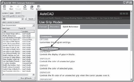
A list of the system variables and their functions could take up a full chapter. A detailed look at system variables is beyond the scope of this book, but you have an excellent resource for information about system variables in the AutoCAD Help window. Click the Help tool (the question mark icon) in the InfoCenter to open the AutoCAD 2010 Help window, or you can press the F1 key. Select the Contents tab, and expand the Command Reference option in the left panel. There you see the system variables listed in alphabetical order.
You can also find system variables through the features and commands they control. For example, if you search for Grip in the AutoCAD 2010 Help window's Search tab (Figure D.1), you'll see Understand Grip Tool at the top of the left panel. Select this option, and a list of system variables related to the Grip feature appears under the Quick Reference tab in the right side panel.
As you saw in Chapter 12, you can control the appearance and format of dimensions through dimension styles. You can create new dimension styles or edit existing ones. The following sections describe all the components of the dialog boxes you use to create and maintain dimension styles.
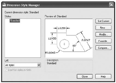
The Dimension Style Manager dialog box is the gateway to dimension styles. With this dialog box, you can create a new dimension style, edit existing dimension styles, or make an existing dimension style current. To open the Dimension Style Manager dialog box (Figure D.2), click the Dimension Style tool on the Annotate tab's Dimensions panel or type Dimstyle
You can use the DesignCenter to import dimension styles from one drawing into another.
The following sections describe the options in the Dimension Style Manager dialog box.
The image in the right half of the Dimension Style Manager dialog box gives you a preview of your dimension style. It shows a sample of most of the types of dimensions you'll use, formatted the way you specified when you created or modified your dimension style.
The Styles list box displays the available dimension styles. You can highlight the dimension style names in the Styles list box to indicate a style to be used with the Set Current, New, Modify, and Override options. You can also right-click a style name and then rename or delete the selected style.
The List drop-down list lets you control what is listed in the Styles list box. You can display either all the styles available or only the styles in use in the drawing.
The Don't List Styles In Xrefs check box lets you specify whether dimension styles in Xrefs are listed in the Styles list box. This option is grayed out if no Xrefs are present in the current drawing.
The Set Current button lets you set the dimension style highlighted in the Styles list box to be current.
The New button lets you create a new dimension style. It uses the dimension style that is highlighted in the Styles list box as the basis for the new style. Clicking New opens the Create New Dimension Style dialog box.

In the Create New Dimension Style dialog box, you can enter the name for your new dimension style. You can also select the source dimension style on which your new dimension style will be based.
- New Style Name
Lets you specify the name for your new dimension style.
- Start With
Lets you select an existing style on which to base your new dimension style.
- Use For
Lets you choose a dimension type for your new dimension style. For a completely new dimension style, use the All Dimensions option in the Use For drop-down list. If you want to modify the specifications for a particular dimension type of an existing dimension style, select a dimension type from this list. Your modified dimension type will appear in the Styles list box under the main style you specify in the Start With drop-down list. After you've modified a dimension type, the new type will be applied to any new dimensions.

After you've entered your options in the Create New Dimension Style dialog box, click Continue. You see the New Dimension Style dialog box described later. When you're finished setting up your new style, it's listed in the Styles list box.
The Modify button lets you modify the dimension style that is selected in the Styles list box. Clicking this option opens the Modify Dimension Style dialog box described later in this appendix.
The Override button lets you create a temporary dimension style based on an existing style. You may want to use this option if you need to create a dimension that differs only slightly from an existing style.
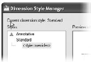
To use the Override option, select a style from the Styles list box, and then click Override. You'll see the Override Current Style dialog box described later. After you create an override, it's listed as <style overrides> in the Styles list box, right under the style you used to create the override.
The override then becomes the default dimension style until you select another one from the Styles list. When you select a different style to be current, a message tells you that the unsaved style will be discarded. To save an override style, select the override from the Styles list box and click New. Then click Continue in the Create New Dimension Style dialog box, and click OK in the New Dimension Style dialog box. You can also merge the override style with its source style by right-clicking <style overrides> and selecting Save To Current Style.
The Compare button lets you compare the differences between two dimension styles. When you click the Compare button, the Compare Dimension Styles dialog box opens (Figure D.3).
You can select the two styles you want to compare from the Compare and With drop-down lists. The differences appear in the list box. Just above the upper-right corner of the list box is a Copy button; this copies the contents of the list box to the Windows Clipboard, enabling you to save the comparison to a word-processed document.

When you click the New button in the Dimension Style Manager dialog box and then click Continue in the Create New Dimension Style dialog box, the New Dimension Style dialog box opens.
You'll also see this same dialog box under a different name when you click the Modify or Override button in the Dimension Style Manager dialog box. The options in this dialog box let you determine all the characteristics of your dimension style. The following sections provide detailed descriptions of each available option.
The equivalent dimension style variables are shown in brackets at the end of the description of each option.
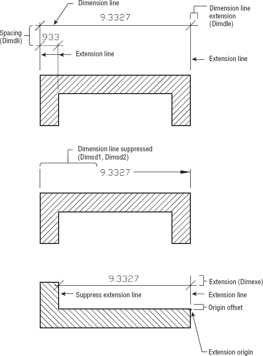
The options in this tab (Figure D.4) give you control over the appearance of dimension and extension lines. Figure D.5 shows an example of some of the dimension components that are affected by these options. The values you enter here for distances should be in final plot sizes and will be multiplied by the dimension scale value in the Fit tab to derive the actual extension distance in the drawing.

The following options let you control the general behavior and characteristics of the dimension lines:
- Color
Lets you set the color of the dimension line [Dimclrd].
- Linetype
Lets you set the linetype for dimension lines.
- Lineweight
Lets you set the lineweight for dimension lines [Dimlwd].
- Extend Beyond Ticks
Lets you set the distance that the dimension line extends beyond the extension lines. The value you enter here should be in final plot sizes and will be multiplied by the dimension scale value in the Fit tab to derive the actual extension distance in the drawing [Dimdle].
- Baseline Spacing
Lets you specify the distance between stacked dimensions [Dimdli].
- Suppress
Check boxes let you suppress the dimension line on either side of the dimension text [Dim Line1, Dim Line 2].
The following options let you control the general behavior and characteristics of the extension lines:
- Color
Lets you set the color for extension lines [Dimclre].
- Linetype Ext Line 1
Controls the linetype for the first extension line.
- Linetype Ext Line 2
- Lineweight
Lets you set the lineweight for extension lines [Dimlwe].
- Extend Beyond Dim Lines
Lets you set the distance that extension lines extend beyond dimension lines [Dimexe].
- Offset From Origin
Lets you set the distance from the extension line to the object being dimensioned [Dimexo].
- Fixed Length Extension Lines
Lets you set the extension lines to a fixed length. The Length input box provides a space to enter the length you want.
- Suppress
Check boxes let you suppress one or both extension lines [Ext Line 1, Ext Line 2].
The options in this tab give you control over the appearance of arrowheads and center marks. The values you enter in this tab for distances should be in final plot sizes and will be multiplied by the dimension scale value in the Fit tab to derive the actual extension distance in the drawing.
The following options let you select the type and sizes of arrowheads for dimensions and leaders:
- First
Lets you select the type of arrowhead to use on dimension lines. By default, the second arrowhead automatically changes to match the arrowhead you specify for this setting [Dimblk1].
- Second
Lets you select a different arrowhead from the one you select for First [Dimblk2].
- Leader
Lets you specify an arrowhead for leader notes [Dimldrblk].
- Arrow Size
Lets you specify the size for the arrowheads [Dimasz].
The following options let you set the center mark for radius and diameter dimensions:
- None/Mark/Line
Let you select the type of center mark used in radius and diameter dimensions. The Mark option draws a small cross mark, Line draws a cross mark and center lines, and None draws nothing [Dimcen].
- Size
Lets you specify the size of the center mark [Dimcen].
This set of radio buttons controls the display of the arc-length symbol in arc-length dimensions:
- Preceding Dimension Text
Places the symbol before the dimension text.
- Above Dimension Text
Places the symbol above the dimension text.
- None
No symbol.
The options in the Text tab (Figure D.6) give you control over the appearance of the dimension text. You can set the text style and default location of text in relation to the dimension line. If the text style you select for your dimension text has a height value of 0, you can set the text height from this tab.
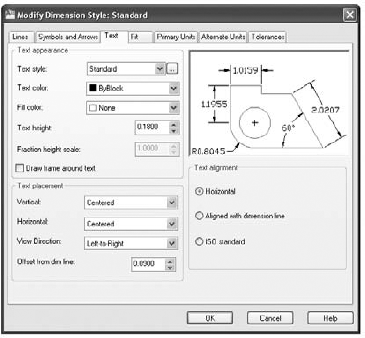
The following options give you control over the appearance of text:
- Text Style
Lets you select an existing text style for your dimension text. You can also create a new style for your dimension text by clicking the Browse button [Dimtxsty].
- Text Color
Lets you select a color for your dimension text [Dimclrt].
- Fill Color
Lets you select a color for your dimension background.
- Text Height
Lets you specify a text height for dimension text. This option is valid only for text styles with 0 height [Dimtxt].
- Fraction Height Scale
Lets you specify a scale factor for the height of fractional text. This option is available only when Architectural or Fractional is selected in the Primary Units tab [Dimtfac].
- Draw Frame Around Text
Draws a rectangle around the dimension text when selected [Dimgap].
The following options give you control over the placement of text, including the ability to specify the distance of text from the dimension line:
- Vertical
Lets you set the vertical position of the text in relation to the dimension line. The options are Centered, Above, Outside, and JIS. Centered places the text in line with the dimension line; the dimension line is broken to accommodate the text. Above places the text above the dimension line, leaving the dimension line unbroken. Outside places the text away from the dimension line at a location farthest from the object being dimensioned. JIS places the text in conformance with the Japanese Industrial Standards [Dimtad].
- Horizontal
Lets you set the location of the text in relation to the extension lines. The options are Centered, At Ext Line 1, At Ext Line 2, Over Ext Line 1, and Over Ext Line 2. Centered places the text between the two extension lines. At Ext Line 1 places the text next to the first extension line but still between the two extension lines. At Ext Line 2 places the text next to the second extension line but still between the two extension lines. Over Ext Line 1 places the text above the first extension line and aligned with the first extension line. Over Ext Line 2 places the text above the second extension line and aligned with the second extension line [Dimjust].
- View Direction
Lets you set the direction of dimension text. The default is Left-to-Right but you can also set it to Right-to-Left [Dtxtdirection].
- Offset From Dim Line
Lets you determine the distance from the baseline of text to the dimension line when text is placed above the dimension line. It also lets you set the size of the gap between the dimension text and the endpoint of the dimension line when the text is in line with the dimension line. You can use this option to set the margin around the text when the dimension text is in a centered position that breaks the dimension line into two segments [Dimgap].
The following options give you control over the alignment of text in relation to the dimension line:
- Horizontal
Keeps the text in a horizontal orientation, regardless of the dimension line orientation.
- Aligned With Dimension Line
Aligns the text with the dimension line.
- ISO Standard
Aligns the text with the dimension line when it's between the extension lines; otherwise the text is oriented horizontally [Dimtih, Dimtoh].
The options in the Fit tab (Figure D.7) let you fine-tune the behavior of the dimension text and arrows under special conditions. For example, you can select an optional placement for text and arrows when there isn't enough room for them between the extension lines.

The Fit Options radio buttons let you determine which dimension component is moved when there isn't enough room between the extension lines for either the text or the arrows or both:
- Either Text Or Arrows (Best Fit)
Automatically determines whether only text, only arrows, or both text and arrows will fit between the extension lines, and then places them accordingly. For example, if there isn't enough room for both text and arrows and the text is wider than the two arrows combined, the text is placed outside the extension lines. If the width of the arrows is greater than the width of the text, the arrows are moved outside the extension lines. If the gap between the extension lines is too narrow for either the text or arrows, both the arrows and the text are moved outside the extension lines [Dimatfit].
- Arrows
Moves the arrows outside the extension lines when there isn't enough room for both arrows and text between the extension lines. If the gap between the extension lines is too narrow for either the text or the arrows, both the arrows and the text are moved outside the extension lines [Dimatfit].
- Text
Moves the text outside the extension lines when there isn't enough room for both arrows and text between the extension lines. If the gap between the extension lines is too narrow for either the text or the arrows, both the arrows and the text are moved outside the extension lines [Dimatfit].
- Both Text And Arrows
Moves both the text and the arrows outside the extension lines when there isn't enough room for both arrows and text between the extension lines [Dimatfit].
- Always Keep Text Between Ext Lines
Places the text between the extension lines regardless of whether the text fits there [Dimtix].
- Suppress Arrows If They Don't Fit Inside Extension Lines
Removes the arrows entirely if they don't fit between the extension lines [Dimsoxd].
The Text Placement radio buttons determine how the dimension text behaves when it's moved from its default location:
- Beside The Dimension Line
Keeps the text in its normal location relative to the dimension line [Dimtmove].
- Over Dimension Line, With Leader
Lets you move the dimension text independent of the dimension line. A leader is added between the dimension line and the text [Dimtmove].
- Over Dimension Line, Without Leader
Lets you move the dimension text independent of the dimension line. No leader is added [Dimtmove].
These options offer control over the scale of the dimension components. You can set a fixed scale, or you can allow the dimension components to be scaled depending on the Paper Space viewport in which they're displayed:
- Annotative
Turns on the Annotative Scale feature, which lets you quickly set the size of text to correspond with your drawing's annotation or viewport scale setting [Annotativedwg].
- Scale Dimensions To Layout
Scales all the dimension components to the scale factor assigned to the Paper Space viewport in which the drawing appears [Dimscale].
- Use Overall Scale Of
Lets you determine the scale of the dimension components. All the settings in the Dimension Style dialog box are scaled to the value you set in the input box if this radio button is selected [Dimscale].
The following two check boxes offer miscellaneous settings for dimension text and dimension lines:
- Place Text Manually
Enables you to manually place the dimension text horizontally along the dimension line when you're inserting dimensions in your drawing [Dimupt].
- Draw Dim Line Between Ext Lines
Forces AutoCAD to draw a dimension line between the extension lines no matter how narrow the distance is between the extension lines [Dimtofl].
The options in the Primary Units tab (Figure D.8) let you set the format and content of the dimension text, including the unit style for linear and angular dimensions.
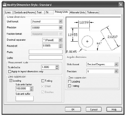
The following options give you control over the unit style and the formatting of dimension text for linear dimensions:
- Unit Format
Lets you determine the unit style of the dimension text. The options are Scientific, Decimal, Engineering, Architectural, Fractional, and Windows Desktop. You must set this option independent of the overall drawing units setting (choose Drawing Utilities

- Precision
Lets you set the precision of the dimension text. This option rounds off the dimension text to the nearest precision value you set. It doesn't affect the actual precision of the drawing [Dimdec].
- Fraction Format
Available only for Architectural and Fractional unit formats. This option lets you select between vertically stacked, diagonally stacked, and horizontal fractions [Dimfrac].
- Decimal Separator
Lets you select a decimal separator for dimension unit formats that display decimals. You can choose a period, a comma, or a space. If you want to use a dimension separator not included in the list, you can use the Dimsep system variable to specify a custom dimension separator [Dimsep].
- Round Off
Lets you determine the degree of rounding applied to dimensions. For example, you can set this option to 0.25 to round off dimensions to the nearest 0.25, or ¼, of a unit [Dimrnd].
- Prefix
Lets you include a prefix for all linear-dimension text. For example, if you want all your linear dimension text to be preceded by the word Approximately, you can enter Approximately in this input box. Control codes can be used for special characters. See Chapter 10 for more information on character codes [Dimpost].
- Suffix
Lets you include a suffix for all linear-dimension text. Control codes can be used for special characters. See Chapter 10 for more information on character codes [Dimpost].
This group offers options that can convert dimension values to different scale factors. For example, dimensions in Imperial units can be scaled to metric and vice versa. The options are as follows:
- Scale Factor
Lets you set a scale factor for the dimension text. This option scales the value of the dimension text to the value you enter. For example, if you want your dimensions to display distances in centimeters, even though the drawing was created in inches, you can enter 2.54 for this option. Your dimension text will then display dimensions in centimeters. Conversely, if you want your dimension text to show dimensions in inches, even though you've created your drawing using centimeters, you enter 0.3937 (the inverse of 2.54) for this option [Dimlfac].
- Apply To Layout Dimensions Only
Causes AutoCAD to apply the measurement scale factor to Paper Space layouts only. With this check box selected, the Dimlfac dimension variable gives a negative value [Dimlfac].
Lets you suppress zeros so they don't appear in the dimension text. For dimensions other than architectural, you can suppress leading and trailing zeros. For example, 0.500 becomes .500 if you suppress leading zeros. It becomes 0.5 if you suppress trailing zeros. For architectural dimensions, you can suppress zero feet or zero inches, although typically you wouldn't suppress zero inches [Dimzin].
Sub-Units Factor lets you control the number of places for numbers to the right of the decimal point. This is helpful if you are working in metric measurements. Sub-Unit Suffix allows you to add a suffix to a dimension. For example, you can enter cm here to display centimeter abbreviation after a sub-unit value.
The following options enable you to format angle dimensions:
- Units Format
Lets you select a format for angular dimensions. The options are Decimal Degrees, Degrees Minutes Seconds, Gradians, and Radians [Dimaunit].
- Precision
Lets you set the precision for the angular dimension text [Dimadec].
The Alternate Units tab (Figure D.9) lets you apply a second set of dimension text labels for dimensions. This second set of text labels can be used for alternate dimension styles or units. Typically, alternate units are used to display dimensions in metric if your main dimensions are in feet and inches.

Select the Display Alternate Units check box to turn on alternate units. This causes AutoCAD to include additional dimension text in the format you specify in the Alternate Units tab [Dimalt].
The following options offer control over the unit style and the formatting of dimension text for linear dimensions:
- Unit Format
Lets you determine the unit style of the dimension text. The options are Scientific, Decimal, Engineering, Architectural Stacked, Fractional Stacked, Architectural, Fractional, and Windows Desktop. You must set this option independent of the overall drawing units setting (choose Drawing Utilities
- Precision
Lets you set the precision of the dimension text. This option rounds off the dimension text to the nearest precision value you set. It doesn't affect the actual precision of the drawing [Dimaltd].
- Multiplier For Alt Units
Lets you set a multiplier value for the dimension text. This option multiplies the value of the dimension text by the value you enter. For example, if you want your alternate dimensions to display distances in centimeters even though the drawing was created in inches, you can enter 2.54 for this option. Your alternate dimension text will then display dimensions in centimeters. Conversely, if you want to have your alternate dimension text show dimensions in inches, even though you've created your drawing by using centimeters, you enter 0.3937 (the inverse of 2.54) for this option [Dimaltf].
- Round Distances To
Lets you determine the degree of rounding applied to alternate dimensions. For example, you can set this option to 0.25 to round off dimensions to the nearest 0.25, or 1'4, of a unit [DImaltrnd].
- Prefix
Lets you include a prefix for all linear alternate dimension text. For example, if you want all linear-dimension text to be preceded by the word Approximately, you can enter Approximately in the Prefix input box. Control codes can be used for special characters. See Chapter 10 for more information on character codes [Dimpost].
- Suffix
Lets you include a suffix for all linear alternate dimension text. Control codes can be used for special characters. See Chapter 10 for more information on character codes [Dimapost].
The check boxes in this group let you suppress zeros so they don't appear in the alternate dimension text. For dimensions other than architectural, you can suppress leading and trailing zeros. For example, 0.500 becomes .500 if you suppress leading zeros. It becomes 0.5 if you suppress trailing zeros. For architectural dimensions, you can suppress zero feet or zero inches, although typically you wouldn't suppress zero inches. The 0 feet and 0 inches options are grayed out until you select the Leading or Trailing options. [Dimaltz].
Sub-Units Factor lets you control the number of places for numbers to the right of the decimal point. This is helpful if you are working in metric measurements. Sub-Unit Suffix allows you to add a suffix to a dimension. For example, you can enter cm here to display the centimeter abbreviation after a sub-unit value.
The following options let you determine the location for the alternate units:
- After Primary Value
Places the alternate dimension text behind and aligned with the primary dimension text [Dimapost].
- Below Primary Value
Places the alternate dimension text below the primary dimension text and above the dimension line [Dimapost].
The options in the Tolerances tab (Figure D.10) offer the inclusion and formatting of tolerance dimension text.

The following options offer control over the format of tolerance dimension text:
- Method
Lets you turn on and set the format for the tolerance dimension text. The options are None, Symmetrical, Deviation, Limits, and Basic. None turns off the tolerance dimension text. Symmetrical adds a plus/minus tolerance dimension; this is a single dimension preceded by a plus/minus sign. Deviation adds a stacked tolerance dimension showing separate upper and lower tolerance values. The Limits option replaces the primary dimension with a stacked dimension showing maximum and minimum dimension values. The Basic option draws a box around the primary dimension value. If an alternate dimension is used, the box encloses both primary and alternate dimension text [Dimtol, Dimlim, (minus) Dimgap].
- Precision
Lets you set the precision of the tolerance dimension text. This option rounds off the dimension text to the nearest precision value you set. It doesn't affect the actual precision of the drawing [Dimtdec].
- Upper Value
Lets you set the upper tolerance value for the Symmetrical, Deviation, and Limits tolerance methods [Dimtp].
- Lower Value
Lets you set the lower tolerance value for the Deviation and Limits tolerance methods [Dimtm].
- Scaling For Height
Lets you adjust the size for the tolerance dimension text as a proportion of the primary dimension text height [Dimtfac].
- Vertical Position
Lets you determine the vertical position of the tolerance text. The options are Top, Middle, and Bottom. The Top option aligns the top tolerance value of a stacked pair of values with the primary dimension text. Middle aligns the gap between stacked tolerance values with the primary dimension text. Bottom aligns the bottom value of two stacked tolerance values with the primary dimension text [Dimtolj].
These radio buttons set the alignment of stacked tolerance values. The two options, Align Decimal Separators and Align Operational Symbols, are self-explanatory.
These options let you suppress zeros so they don't appear in the tolerance dimension text. For dimensions other than architectural, you can suppress leading and trailing zeros. For example, 0.500 becomes .500 if you suppress leading zeros. It becomes 0.5 if you suppress trailing zeros. For architectural dimensions, you can suppress zero feet or zero inches, although typically you wouldn't suppress zero inches [Dimtzin].
The Precision drop-down list lets you set the precision of the alternate tolerance dimension text. This option rounds the dimension text to the nearest precision value you set. It doesn't affect the actual precision of the drawing [Dimalttd]. You can also control zero suppression (see 'The Zero Suppression Groups,' mentioned previously).
The AutoCAD user community is worldwide, and many of you may be using the metric system in your work. As long as you aren't mixing Imperial (feet and inches) and metric measurements, using the metric version of AutoCAD is fairly easy. In the Drawing Units dialog box (choose Drawing Utilities
If your drawings are to be in both Imperial and metric measurements, you'll be concerned with several settings, as follows:
- Dimlfac
Sets the scale factor for dimension values. The dimension value will be the measured distance in AutoCAD units times this scale factor. Set Dimlfac to 25.4 if you've drawn in inches but want to dimension in millimeters. The default is 1.0000. If you want to scale dimension values from millimeters to inches, use a value of 0.03937.
- Dimalt
Turns the display of alternate dimensions on or off. Alternate dimensions are made up of dimension text added to your drawing in addition to the standard dimension text.
- Dimaltf
Sets the scale factor for alternate dimensions (that is, to metric from Imperial). The default is 25.4, which is the millimeter equivalent of 1″. If you're using metric ISO units, the default is 0.03937, which is the inch equivalent of 1 mm.
- Dimaltd
Sets the number of decimal places displayed in the alternate dimensions.
- Dimapost
Adds a suffix to alternate dimensions, as in 4.5 mm.
If you prefer, you can use the metric template drawing supplied by AutoCAD:
Choose New from the Quick Access toolbar. If you see the Select Template dialog box, go to step 2; otherwise, skip to step 3.
Select the
Acadiso.dwtfile and click Open. You can also select acadISO ' Named Plot Styles.dwt if you want to use a named plot style.In the Create New Drawing dialog box, click the Template button. Then select the filename
Acadiso.dwtand click OK to open a new drawing based on the template. You can also select acadISO ' Named Plot Styles.dwt if you want to use a named plot style.
These templates are set up for metric/ISO standard drawings.
You can also click the Metric radio button in the Start From Scratch option of the Create New Drawing dialog box. When you do so, subsequent new files will be set to metric by default.
If the AutoCAD 2010 Startup dialog box doesn't appear when you open AutoCAD, or if you don't see the Create New Drawing dialog box when you choose New from the Application menu, you can turn on these dialog boxes by using the Startup option in the System tab of the Options dialog box. Choose Options from the Application menu, and then click the System tab in the Options dialog box. In the General Options group, select Show Startup Dialog Box from the Startup drop-down list.
If you don't want to use the arrowheads supplied by AutoCAD for your dimension lines, you can create a block of the arrowheads or tick marks you want, to be used in the Arrowheads group of the Dimension Styles/Geometry dialog box.
To access the Arrowhead options, open the Symbols And Arrows tab of the New, Modify, Or Override Dimension Style dialog box.
For example, suppose you want a tick mark that is thicker than the dimension lines and extensions. You can create a block of the tick mark on a layer you assign to a thick pen weight and then assign that block to the Arrowhead setting. To do so, type Dimstyle
When you draw the arrow block, make it 1 unit long. The block's insertion point will be used to determine the point of the arrow that meets the extension line, so make sure you place the insertion point at the tip of the arrow. Because the arrow on the right side of the dimension line will be inserted with a zero rotation value, create the arrow block so that it's pointing to the right (see Figure D.11). The arrow block is rotated 180' for the left side of the dimension line.

If you want a different type of arrow at both ends of the dimension line, create a block for each arrow. In the Dimension Styles/Geometry dialog box, choose User in the drop-down list for the first arrowhead and enter the name of one block. Then choose User in the drop-down list for the second arrowhead and enter the name of the other block.