
Because some of the items that make up an AutoCAD system aren't found on the typical desktop system, I have provided this appendix to help you understand them. This appendix also discusses ways you can improve AutoCAD's performance through software and hardware.
There are two issues to consider concerning the graphics display: resolution and performance. Fortunately, nearly all computers sold today have display systems that are more than adequate for AutoCAD, thanks to the popularity of 3D games. You do need to make sure that your resolution is set to at least 1024 × 768, preferably higher. The higher your resolution, the more detail you'll be able to see in your drawings.
If you have an older system that needs a graphics display upgrade, you should consider the following factors in choosing a new display.
Contemporary motherboards use high-speed PCI Express (PCIe) slots that offer the fastest video throughput available. Check that your system is of this type. If you're doing only 2D work, you can get by with an older Accelerated Graphics Port (AGP) graphics card. Windows Vista and Windows XP also provide options for using multiple monitors, an approach that has been popular among AutoCAD users. Multiple monitors enable AutoCAD users to view multiple or large documents more easily.
If you want to take full advantage of AutoCAD's new 3D features, you'll want one of the Autodesk-certified graphics cards in your system. To get the most up-to-date information on the latest graphics-card support, check the Autodesk Service and Support website by doing the following:
Enter 3dconfig at the Command prompt.
In the Adaptive Degradation And Performance Tuning dialog box, click the Check For Updates button. Your default browser opens to the Autodesk Service and Support page, where you'll find a description of general hardware issues.
Click the Graphics Hardware List option in the left column of the page to go to the page that gives you more detailed information about available graphics hardware drivers.
Even if you already have one of these cards, make sure you have the latest drivers. You can go to the Autodesk web page and download the appropriate driver by doing the following:
Choose Options from the Application menu, and select the System tab.
Click the Performance Settings button. Then, in the Adaptive Degradation And Performance Tuning dialog box, click the Check For Updates button.
The Autodesk AutoCAD Certified Hardware XML Database page opens. You can locate driver updates on this page.
The basic means of communicating with a computer is through its keyboard and pointing device. Most likely you'll use a mouse, but if you're still in the market for a pointing device, choose an input device that generates smooth cursor movement. Some of the lesser-quality input devices cause erratic movement. Because AutoCAD relies on precise input, you may want to upgrade to an optical mouse, which is less likely to wear out or accumulate dirt in its mechanism.
If you need to trace large drawings, you may want to consider a digitizing tablet. It's usually a rectangular object with a penlike stylus or a device called a puck, which resembles a mouse. It has a smooth surface on which to draw. The most common size is 4″ × 5″, but digitizing tablets are available in sizes up to 60″ × 70″. The tablet gives a natural feel to drawing with the computer because the movement of the stylus or puck is directly translated into cursor movement.
AutoCAD supports Wintab-compatible digitizers. If your digitizer has a Wintab driver, you can use your digitizer as both a tracing device (to trace drawings on a tablet) and a general pointing device for Windows to choose program menu items.
Your Wintab digitizer must be installed and configured under Windows. Make sure it's working in Windows before enabling it in AutoCAD or you won't be able to use the digitizer as a pointing device (mouse). To enable the digitizer in AutoCAD, choose Options from the Application menu to open the Options dialog box, and click the System tab. Open the Current Pointing Device drop-down list, and select Wintab Compatible Digitizer ADI 4.2 – by Autodesk, Inc.
Output options vary greatly in quality and price. Quality and paper size are the major considerations for printers. Nearly all printers give accurate drawings, but some produce better line quality than others. Some plotters give merely acceptable results, whereas others are impressive in their speed, color, and accuracy.
AutoCAD can use the Windows Vista or XP system printer, so any device that Windows supports is also supported by AutoCAD. You can also plot directly to an output device, although Autodesk recommends that you set up your plotter or printer through Windows and then select the device from the Plot Configuration group in the Plot Device tab of the Plot dialog box or the Page Setup dialog box.
In Chapter 8, you were introduced to AutoCAD's printing and plotting features. You learned about the AutoCAD features you can use to control the appearance of your output, including layouts and lineweights. The following sections cover some of the finer points of printer and plotter setup. You'll find information about controlling how lines overlap, how to include more media sizes, adding plot stamps, adjusting the aspect ratio of your printer, and more.
If you open the Plot dialog box or the Page Setup dialog box, you see the option groups that offer control over how your plotter or printer works. These groups seem innocent enough, but behind two of them lies a vast set of options that can be quite intimidating. You've already seen in Chapter 8 how the Plot Style Table options work. This section covers the options available when you click the Properties button in the Printer/Plotter group.
The Printer/Plotter Configuration options enable you to adjust those printer or plotter settings that you may want to change only occasionally. These settings are fairly technical and include such items as the port your printer is connected to, the quality of bitmap-image printing, custom paper sizes, and printer calibration, which lets you adjust your plotter for any size discrepancies in output. You won't use most of these settings often, but you should know that they exist just in case you encounter a situation in which you need to make some subtle change to your printer's configuration. You can also use these options to create multiple configurations of the same plotter for quick access to custom settings.
All the settings in this group are stored in a file with the .pc3 filename extension. You can store and recall any number of configuration files for situations that call for different plotter settings. PC3 files are normally stored in the Plotters folder under the following folder:
C:Documents and SettingsUsername
ApplicationDataAutodeskAutoCAD 2010R18.0enu
Username is your login name. You can access this folder by choosing Print
The Printer/Plotter group in the Plot and Page Setup dialog boxes offers a drop-down list from which you can select a printer or file output configuration. If a PC3 file exists for a plotter configuration, the drop-down list displays it, and the list displays any Windows system printer. After you've selected an output device from the list, you can click the Properties button to access the Plotter Configuration Editor dialog box.
You can configure AutoCAD to create bitmap files in the most common file formats (such as PDF, TIFF, Targa, and PCX) or to create files in Autodesk's DWF file format for the Internet. After you've configured AutoCAD for these types of output, the Plotter Configuration Editor dialog box is where you select the file output type.
The Plotter Configuration Editor dialog box has three tabs: General, Ports, and Device And Document Settings. The General tab displays a list of Windows drivers that this configuration uses, if any, and there is a space for your own comments.
You can access and edit the plotter configuration settings without opening AutoCAD. To do this, locate the PC3 file in the Plotters subfolder under the
C:Documents and SettingsUsernameApplication DataAutodeskAutoCAD 2010R18.0enuPlottersfolder (Username is your login name), and double-click it.
The Ports tab lets you specify where your plotter data is sent. This is where you should look if you're sending your plots to a network plotter or if you decide to create plot files. You can also select the AutoSpool feature, which enables you to direct your plot to an intermediate location for distribution to the appropriate output device.
The Device And Document Settings tab (Figure C.1) is the main part of this dialog box. It offers a set of options ranging from OLE output control to custom paper sizes. The main list box offers options in a hierarchical list, similar to a listing in Windows Explorer. Toward the bottom of the dialog box are the Import, Save As, and Defaults buttons. These buttons let you import configuration settings from earlier versions of AutoCAD, save the current settings as a file, or return the settings to their default values.
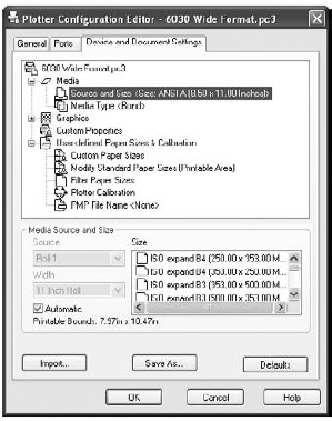
The list has four main categories: Media, Graphics, Custom Properties, and User-Defined Paper Sizes & Calibration. Not all the options under these categories are available for all plotters. When you select an item from this list, the area just below the list displays the options associated with that item. The following sections describe each category and its options, using the Xerox Engineering Systems XES6050 as an example.
Some plotters, such as the Xerox Engineering Systems 8800 series, offer options for the source and size of printer media and for the media type. If the Source And Size option is available, the dialog box offers a listing of the sources, such as sheet feed or roll, and the sheet sizes. The Media Type option lets you choose from bond, vellum, or glossy paper or any other medium that is specifically controlled by the plotter. Duplex Printing, when available, controls options for double-sided printing in printers that support this feature. Media Destination, when available, lets you select a destination for output such as collating or stapling in printers that support such features.
Pen plotters have features that diverge from the typical laser or ink-jet printers or plotters. When these options are present, they let you control some of the ways that AutoCAD generates data for pen plotters. Here is a listing of those pen-plotter feature settings:
- Prompt For Pen Swapping
Stops the plotter to enable you to switch pens. This feature is designed primarily for single-pen plotters.
- Area Fill Correction
Tells AutoCAD to compensate for pen width around the edges of a solid-filled area in order to maintain dimensional accuracy of the plot.
- Pen Optimization Level
Sets how AutoCAD sorts pen movement for optimum speed. AutoCAD does a lot of preparation before sending your drawing to the plotter. If you're using a pen plotter, one of the things it does is optimize the way it sends vectors to your plotter so your plotter doesn't waste time making frequent pen changes and moving from one end of the plot to another just to draw a single line.
- Physical Pen Characteristics
Lets you assign plotter pen numbers to AutoCAD colors, adjust the speed of individual pens, and assign pen widths.
These settings give you control over both vector and raster output from your plotter. The Vector Graphics settings let you control resolution and color depth as well as the method for creating shading. If you want to configure your printer for virtual pens, select 255 Virtual Pens under the Color Depth option.
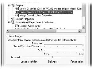
The Raster And Shaded/Rendered Viewports slider gives you control over the quality of any bitmap images. If this slider is placed all the way to the left, raster images aren't plotted. As you move the slider to the right, the raster image quality increases, the speed of printing decreases, and memory requirements increase. The OLE slider controls the quality of OLE linked or embedded files. With the slider all the way to the left, OLE objects aren't printed. As you move the slider farther to the right, OLE image quality and memory requirements increase while speed is reduced.
The Trade-Off slider (Figure C.2) lets you choose how the Raster and OLE sliders improve speed. You can choose between lower resolution and fewer colors.
For printers and plotters that support TrueType fonts, the TrueType Text options enable you to select between plotting text as graphics or as TrueType text.
Select Custom Properties from the Device And Document Settings tab and the Custom Properties button appears in the lower part of the dialog box. This button gives you access to the same printer or plotter settings that are available from the Windows system printer settings. You can also access these settings by choosing Start
The options offered through the Custom Properties button often duplicate many of the items in the Device And Documents tab. If an option isn't accessible from the Device And Documents tab, select the options under Custom Properties.
Some plotters require preinitialization and postinitialization codes in the form of ASCII text strings to get the plotter's attention. If you have such a plotter, this option lets you enter those strings.
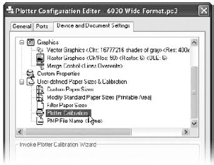
The User-Defined Paper Sizes & Calibration category offers some of the more valuable options in this dialog box. In particular, the Plotter Calibration option can be useful in ensuring the accuracy of your plots.
If your printer or plotter isn't producing an accurate plot, focus on the Plotter Calibration option. If your plotter stretches or shrinks your image in one direction or another, this option lets you adjust the width and height of your plotter's output. To use it, click Plotter Calibration (Figure C.3).
A Calibrate Plotter button appears. Click this button to start the Calibrate Plotter Wizard. You're asked first to select a paper size and then to select a width and height for a rectangle that will be plotted with your printer. Figure C.4 shows the wizard screen that asks for the rectangle size.

Figure C.4. The Calibrate Plotter Wizard lets you adjust the width and height scaling of your plotter output in order to fine-tune the accuracy of your plots.
You can use the Calibrate Plotter Wizard to plot a sample rectangle of a specific size. You then measure the rectangle and check its actual dimensions against the dimensions that you entered. If there are any discrepancies between the plotted dimensions and the dimensions you specified, you can enter the actual plotted size and print another test rectangle. You can repeat this process until your plotted rectangle exactly matches the dimensions entered into the wizard.
Toward the end of the Calibrate Plotter Wizard's steps, you're asked to give a name for a Plot Model Parameter (PMP) file that will store your calibration data. The PMP file also stores any custom paper-size information that you input from other parts of the User-Defined Paper Sizes & Calibration options. This file is then associated with the PC3 file that stores your plotter configuration data.
If you have more than one PC3 file for your plotter, you can associate the PMP file with your other PC3 files by using the PMP File Name option (Figure C.5) in the Device And Document Settings tab. You need only one calibration file for each plotter or printer you're using. This option appears under the User-Defined Paper Sizes & Calibration category.

To associate a PMP file with a PC3 plotter configuration file, select the PC3 file from the Name drop-down list in the Printer/Plotter section of the Plot dialog box. Click the Properties button, and then, in the Device And Document Settings tab, click the PMP File Name listing. The PMP options appear in the bottom of the dialog box. Click the Attach button, and then select the PMP file from the Open dialog box. Click OK. You'll see that the PMP file has been added to the PMP filename listing.
Some plotters offer custom paper sizes. This feature is usually available for printers and plotters that you've set up to use the AutoCAD drivers instead of the Windows system drivers. If your plotter offers this option, you see a list box and a set of buttons when you select Custom Paper Sizes (Figure C.6).
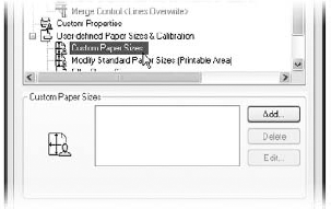
Clicking the Add button starts the Custom Paper Size Wizard, which lets you set the sheet size and margin as well as the paper source. This information is then saved in a PMP file. You're asked to provide a specific name for the custom paper size, which will be listed in the Custom Paper Size list box.
After you've created a custom paper size, you can edit or delete it by clicking the Edit or Delete button in the Custom Paper Sizes options.
The last item in the Device And Document Settings tab is the Modify Standard Paper Size option. If this option is available, you can adjust the margins of a standard paper size.
If you're using an older pen plotter, you'll see the Physical Pen Configuration options in the Device And Document Settings tab. These additional options give you control over pen speed, pen optimization, and area fill correction.
The Import, Save As, and Defaults buttons at the bottom of the Plotter Configuration Editor let you import or save your plotter settings as PC3 files, which you can then load from the Plot Device tab of the Plot dialog box and the Page Setup dialog box, as described earlier in this appendix. The Import button lets you import PCP and PC2 files from earlier versions of AutoCAD. Save As lets you save your current settings under an existing or a new PC3 filename. The Defaults button restores the default settings, if any, for the current plotter configuration.
To help cross-reference your printer or plotter output to AutoCAD drawing files, it's a good idea to add a plot stamp to your drawings so you can identify the date, time, and filename of the drawing that generated your plot. To accomplish this, the Plot Stamp feature lets you imprint data onto your plotted drawings, usually in the lower-left corner. In addition, Plot Stamp lets you keep a record of your plots in a log file.
To use Plot Stamp, type Plotstamp
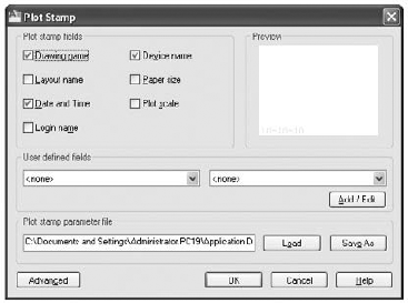
The Plot Stamp dialog box offers several options that let you determine what to include in the stamp.
If the options are grayed out, click the Save As button to save Plot Stamp settings under a new file.
The Plot Stamp Fields group lets you include seven predefined options in your stamp, including drawing, layout, and output device name. The User Defined Fields group lets you add custom text to the stamp. To use this feature, click the Add/Edit button in the User Defined Fields group. The User Defined Fields dialog box opens (Figure C.8).

You can use the Add, Edit, or Delete button to add or make changes to the user-defined fields. After you add a field, it appears in both the list boxes in the User Defined Fields group of the Plot Stamp dialog box.
To control the location, orientation, font, and font size of the plot stamp, click the Advanced button in the lower-left corner of the Plot Stamp dialog box to open the Advanced Options dialog box, shown in Figure C.9.

This dialog box lets you specify the orientation of the stamp on the page as well as the exact location of the stamp in relation to either the printable area or the paper border. In addition, you can specify whether to save a record of your plotting activities in a log file by using the Log File Location group.
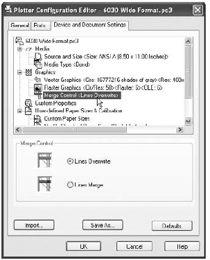
Some output devices let you control how overlapping lines and shaded areas affect one another, a feature known as merge control. In versions of AutoCAD prior to 2000, merge control was handled through additional commands such as Hpconfig or OCEconfig. AutoCAD 2010 includes merge control as part of the Plotter Configuration Editor dialog box.
You can gain access to merge control by opening the Plotter Configuration Editor and, in the Graphics area of the Device And Document Settings tab, clicking the plus sign next to Graphics to expand the list of Graphics options.
If your device supports merge control, you'll see it listed under Graphics, as shown in Figure C.10.
AutoCAD displays all the available paper sizes for a selected output device in the Page Setup dialog box or the Plot dialog box. For some plotters, the list can be a bit overwhelming. You can filter out paper sizes that you don't need by using the Filter Paper Sizes option in the Plotter Configuration Editor.
Open the Plotter Configuration Editor, and click the plus sign next to the User-Defined Paper Sizes & Calibration item. You see Filter Paper Sizes as an option. After you select this option, you see the Filter Paper Sizes area in the lower half of the Plotter Configuration Editor. Remove the check mark in the box next to any size you won't need.
In some instances, you may want to hide the Windows system printer from the list of printers shown in the AutoCAD Plot dialog box. For example, there may be several shared system printers on a network that aren't intended for AutoCAD use, so you wouldn't want those printers to appear in your list of available printers. You can do this by turning on the Hide System Printers option at the bottom of the General Plot Options group in the Plot And Publish tab of the Options dialog box (choose Options from the Application menu). This limits the selection of printers and plotters to those that have a PC3 plotter configuration. You can further limit the plotter selections by moving any unneeded PC3 files out of the AutoCAD Plotters folder and into another folder for storage.
If you prefer to use a color other than white for the plot-preview background, you can set the plot-preview background color by using the Color Options dialog box:
If you prefer using the Windows metafile file type to export AutoCAD drawings to other programs, you can control the background color of your exported file. The AutoCAD Wmfbkgnd system variable lets you control the background color of exported Windows metafiles. Wmfbkgnd offers two settings: off generates a transparent background, and on generates the background color of the current view. The initial default value is off.
Next to your computer's CPU, memory has the greatest impact on AutoCAD's speed. How much you have, and how you use it, can make a big difference in whether you finish that rush job on schedule or work late nights trying. The following sections will clarify some basic points about memory and how AutoCAD uses it.
AutoCAD is a virtual memory system. This means that when your RAM resources reach their limit, part of the data stored in RAM is temporarily moved to your hard disk to make more room in RAM. This temporary storage of RAM to your hard disk is called virtual memory paging. Through memory paging, AutoCAD continues to run, even though your work may exceed the capacity of your RAM. The Windows operating system manages this virtual memory paging. If you have several programs open at once, Windows determines how much memory to allocate to each program. AutoCAD always attempts to store as much of your drawing in RAM as possible. When the amount of RAM required for a drawing exceeds the amount of physical RAM in your system, Windows pages parts of the data stored in RAM to the hard disk. Your drawing size, the number of files you have open in AutoCAD, and the number of programs you have open under Windows affect how much RAM you have available. For this reason, if your AutoCAD editing session is slowing down, try closing other applications you may have open or closing files that you're no longer using. This will free up more memory for AutoCAD and the drawing file.
You'll notice that AutoCAD slows down when paging occurs. If this happens frequently, the best thing you can do is add more RAM. But you can also improve the performance of AutoCAD under these conditions by ensuring that you have adequate hard-disk space and that free hard-disk space has been defragmented or optimized. A defragmented disk offers faster access, thereby improving paging speed.
Windows dynamically allocates swap-file space. However, make sure there is enough free space on your hard disk to allow Windows to set up the space. A good guideline is to allow enough space for a swap file that is twice the size of your RAM capacity. If you have the minimum 1GB of RAM, you need to allow space for a 1024MB swap file (at a minimum). This will give your system 1024MB of virtual memory. Also consider setting the minimum and maximum swap file space to be equal.
Fast, high-capacity hard disks are fairly inexpensive, so even if you aren't running out of space, you may want to consider adding another hard disk with as much capacity as you can afford. You can greatly improve your system speed by upgrading from an old hard drive to a new one. Consider upgrading to an SATA or SATA2 hard-drive controller and drive. You may also consider a Raid-0 hard-drive setup if your system supports it. Raid-0 can greatly improve the speed of your system by dividing hard-drive access between two drives. Such a system can nearly double access speeds.
If you aren't in the habit of emptying your Recycle Bin, you'll want to get into the habit of doing so. Every file that you "delete" using Windows Explorer is actually passed to the Recycle Bin. You need to clear this out frequently. If you're a regular Internet user, check your Internet cache folder for unnecessary files. You can employ one of the many hard-disk cleaning utilities to do this. Finally, it's a good idea to perform regular maintenance on your hard disk to keep it clear of fragmentation and unused files. The Tools tab of the Properties dialog box for your hard disk offers error-checking and defragmenting options.
AutoCAD offers some tools to help make your use of system memory more efficient. Partial Open and the Spatial and Layer indexes let you manage the memory use of large drawings and multiple open files by reducing the amount of a file that is loaded into memory. Using these tools, you can have AutoCAD open only those portions of a file that you want to work on.
Use the Partial Open option in the File dialog box when you know you're going to work on only a small portion or a particular set of layers of a large drawing. Choose Open from the Application menu, and then locate and select the file you want to open. At the bottom-right corner of the dialog box, click the down arrow next to the Open button, and select Partial Open to open the Partial Open dialog box (Figure C.11). Note that this option is available only for files created and edited in AutoCAD 2000 and later.
You can use this dialog box to open specific views of your drawing by selecting the view name from the View Geometry To Load list box. Only the geometry displayed in the selected view is loaded into memory. This doesn't limit you to only that view as you edit the drawing. Subsequent views cause AutoCAD to load their geometry as needed.
You can further limit the amount of a drawing that is loaded into memory by selecting only those layers you want to work with. Place a check mark next to the layers you want in the Layer Geometry To Load list box.

After you open a file by using the Partial Open option, you can always make further adjustments by typing Partiaload
The Spatial and Layer indexes are lists that keep a record of geometry in a drawing. A Spatial index lists a drawing's geometry according to the geometry's location in space. A Layer index lists the drawing's geometry according to layer assignments. These indexes offer more-efficient memory use and faster loading times for drawings that are being used as Xrefs. They take effect only when Demand Load is turned on. (See Chapter 7 for more on Demand Load.) The Layer index enables AutoCAD to load only those layers of an Xref that aren't frozen. AutoCAD uses the Spatial index to load only objects in an Xref that are within the boundary of a clipped Xref.
You can turn on the Spatial and Layer indexes for a file through the Indexctl system variable. Indexctl has four settings:
0 is the default. This turns off Spatial and Layer indexing.
1 turns on Layer indexing.
2 turns on Spatial indexing.
3 turns on both Layer and Spatial indexing.
To use the Indexctl system variable, type Indexctl
The Partial Open option in the Select File dialog box includes the Index Status button group, which offers information on the index status of a drawing. If the drawing you're opening has Spatial or Layer indexing turned on, you can use it by selecting the Spatial Index check box.
If your disk is getting crowded and you need to squeeze as many files as you can onto it, you can reduce the amount of wasted space in a file by adjusting the Incremental Save value in the Open And Save tab of the Options dialog box. By setting Incremental Save to a lower value, you can reduce the size of files to some degree. The trade-off is slower performance when saving files. See Appendix B for more information on this setting.
Another related option is to turn off the BAK file option, also located in the Open And Save tab of the Options dialog box. Each time you save a file, AutoCAD creates a backup copy of your file with the .bak filename extension. When you turn off the Create Backup Copy With Each Save option, BAK files aren't created, thereby saving disk space.
Many users who have Architectural Desktop 2010 (ADT) would like to use this book to learn AutoCAD 2010. However, the interface to ADT is quite different from the standard AutoCAD interface. Still, underneath the ADT menus and palettes lies the basic AutoCAD program discussed in this book. If you have Architectural Desktop 2010, the following instructions show you how to set up a shortcut on your Windows Desktop to launch standard AutoCAD 2010:
To make a copy of the ADT Windows Desktop shortcut, right-click the Architectural Desktop 2010 shortcut, and choose Copy.
Right-click a blank spot on the Desktop, and choose Paste.
Right-click the copy of the ADT shortcut, and choose Properties.
In the Target text box, change the value to read as follows:
"C:Program FilesAutodesk Architectural Desktop 2010
acad.exe" /t "acad.dwt" /p "Standard AutoCAD"
Note that this example is broken into two lines so it can fit on the page. You should enter it as a single line. The
/tis a command switch that tells AutoCAD to use a specific template file, which in this case isacad.dwt. The/pis a command switch that tells AutoCAD to use the Standard AutoCAD profile when starting AutoCAD. Note that the Standard AutoCAD profile doesn't exist. AutoCAD creates it when you attempt to start AutoCAD from the shortcut. Click Apply after you've made the change to the Target text box.Click the Change Icon button, and then click the Browse button in the Change Icon dialog box. From here, you can select a different icon from the Change Icon dialog box.
Click OK to exit the Shortcut Properties dialog box. Then, right-click the shortcut copy again and choose Rename.
Rename the shortcut to AutoCAD 2010.
Double-click your new AutoCAD 2010 Desktop shortcut to start AutoCAD 2010. You'll see a warning message that the Standard AutoCAD profile doesn't exist and that AutoCAD will create it using the default AutoCAD settings. Once AutoCAD has started, the title bar will still show Autodesk Architectural Desktop 2010, but the program will behave like standard AutoCAD 2010. You can still start the full version of Architectural Desktop by using the Architectural Desktop 2010 shortcut or if you launch AutoCAD by double-clicking an AutoCAD file.
AutoCAD is a complex program and, at times, doesn't behave in a way you expect. If you run into problems, chances are they won't be insurmountable. Here are a few tips on what to do when AutoCAD doesn't work the way you expect.
The most common reason you'll have difficulty opening a file is a lack of free disk space. If you encounter errors attempting to open files, check whether you have adequate free disk space on all your drives.
If you've recently installed AutoCAD but you can't start it, you may have a configuration problem. Before you panic, try reinstalling AutoCAD from scratch. Particularly if you're installing the CD version, this doesn't take long. (See Appendix B for installation instructions.) Before you reinstall AutoCAD, use the Uninstall program to remove the current version of AutoCAD. After you've uninstalled AutoCAD, delete the AutoCAD 2010 folder from the Program Files folder and also delete the AutoCAD 2010 folders under the following two locations:
C:Documents and SettingsUsernameApplication DataAutodesk
C:Documents and SettingsUsernameLocal SettingsApplication DataAutodesk
Make sure you have your authorization code, serial number, and CD key handy. Make sure you've closed all other programs when you run the AutoCAD installation. As a final measure, restart your computer when you've completed the installation.
Hardware failures can result in data files becoming corrupted. When this happens, AutoCAD is unable to open the drawing file. Fortunately, there is hope for damaged files. In most cases, AutoCAD runs through a file-recovery routine automatically the next time you open it after a crash. You'll see a panel on the left side of the AutoCAD window listing files that are available for recovery, including BAK files. You can double-click the file you want to recover and then save it.
If you have a file you know is corrupted but it doesn't appear in the panel described in the previous paragraph, you can start the file-recovery utility by choosing Drawing Utilities
Another possibility is to attempt to recover your drawing from the BAK file—the last saved version before your drawing was corrupted. Rename the BAK file as a DWG file with a different name, and then open it. The drawing will contain only what was in your drawing when it was previously saved.
If you want to restore a file that you've just been working on, you can check the file with the alphanumeric name and the .sv$ filename extension. This is the file AutoCAD uses to store your drawing during automatic saves. Change the .sv$ filename extension to .dwg, and then open the file.
In some situations, a file is so badly corrupted it can't be restored. By backing up frequently, you can minimize the inconvenience of such an occurrence. You may also want to consider a third-party utility that performs regular disk maintenance.
AutoCAD is a large and complex program, so you're bound to encounter difficulties from time to time. This section covers a few of the more common problems experienced while using AutoCAD.
- You cannot open a file that others in your group are able to open
This may be happening because you have a corrupted temporary file. You can usually correct this problem by doing the following: Open the AutoCAD temporary drawing file location. This is usually
C:Documents and SettingsUsernamelocal settings empwhereUsernameis your name. Delete the SV$ and AC$ files from this folder. Note that the SV$ files are the automatic save files and you can restore them to regular AutoCAD files by changing the.sv$filename extension to.dwg.- You can see but can't select objects in a drawing someone else has worked on
This may be happening because you have a Paper Space view instead of a Model Space view. To make sure you're in Model Space, type Tilemode

- Grips don't appear when objects are selected
Make sure the Grips feature is enabled. See Appendix B for details.
- Selecting objects doesn't work as described in this book
Check the Selection settings to make sure they're set the same way as the exercise specifies. See "Selecting Objects" in Chapter 2 for details. Also check the Selection tab in the Options dialog box (choose Options from the Application menu). See Appendix B for more on the Selection tab of the Options dialog box.
- Text appears in the wrong font style or an error message says AutoCAD can't find font files
When you're working on files from another company, it's not uncommon that you'll encounter a file that uses special third-party fonts you don't have. You can usually substitute standard AutoCAD fonts for any fonts you don't have without adverse effects. AutoCAD automatically displays a dialog box that lets you select font files for the substitution. You can either choose a font file or press the Esc key to ignore the message. (See Chapter 10 for more on font files.) If you choose to ignore the error message, you may not see some of the text that would normally appear in the drawing.
- You can't import DXF files
Various problems can occur during the DXF import, the most common of which is that you're trying to import a DXF file into an existing drawing rather than a new drawing. Under some conditions, you can import a DXF file into an existing drawing by using the Dxfin command, but AutoCAD may not import the entire file.
To ensure that your entire DXF file is safely imported, choose Open from the Application menu, and select *.DXF from the File Type drop-down list. Then import your DXF file.
If you know that the DXF file you're trying to import is in the ASCII format and not a binary DXF, look at the file with a text editor. If it contains odd-looking lines of characters, chances are the file is damaged or contains extra data that AutoCAD can't understand. Try deleting the odd-looking lines of characters, and then import the file again. (Make a backup copy of the file before you attempt this.)
- A file can't be saved to disk
Frequently, a hard disk will fill up quickly during an editing session. AutoCAD can generate temporary and swap files many times larger than the file you're editing. This may leave you with no room to save your file. If this happens, you can empty the Recycle Bin to clear some space on your hard disk or delete old AutoCAD BAK files you don't need. Don't delete temporary AutoCAD files.
- The keyboard shortcuts for commands aren't working
If you're working on an unfamiliar computer, chances are the keyboard shortcuts (or command aliases) have been altered. The command aliases are stored in the
Acad.pgpfile. Use the Windows Search utility to locate this file, and make sure theAcad.pgpfile is in theC:Documents and SettingsUsernameApplication DataAutodeskAutoCAD 2010R18.0enuSupportfolder.- Plots come out blank
Check the scale factor you're using for your plot. Often, a blank plot means your scale factor is making the plot too large to fit on the sheet. Try plotting with the Scale To Fit option. If you get a plot, you know your scale factor is incorrect. See Chapter 8 for more on plotting options. Check your output before you plot by using the Full Preview option in the Plot Configuration dialog box. In addition, if only parts of a drawing are not showing up in a plot, try running the Audit command.
- Dimensions appear as objects or lines and text and don't act as described in this book
The Dimassoc system variable has been set to 0 or was 0 when the dimension was created. Another possibility is that the dimension was reduced to its component objects by using the Explode command. Make sure Dimassoc is on by typing Dimassoc
2. Unfortunately, an exploded dimension or one that was created with Dimassoc turned off can't be converted to a true dimension object. You must redraw the dimension.- A file containing an Xref appears to be blank, or parts are missing
AutoCAD can't find the Xref file. Use the External Reference palette (click the External Reference tool on the Insert tab's Reference panel title bar) to reestablish a connection with the Xref file. After the External Reference palette is open, select the missing Xref from the list, and then click the Found At option in the Details panel of the palette. Click the Browse button in the input box to the right of the Found At option and locate and select the file by using the Browse dialog box.
You may also want to run the Audit tool to make sure your current and Xref files are not corrupted. Choose Drawing Utilities

- As you draw, little marks appear on your screen where you have selected points
The Blipmode system variable is on. Turn it off by typing Blipmode
- A file you want to open is read-only, even though you know no one else on the network is using it
Every now and then, you may receive a file that you can't edit because it's read-only. This frequently happens with files that have been archived to a CD. If you have a file that is read-only, try the following:
Locate the read-only file with Windows Explorer, and right-click its filename.
Choose Properties from the shortcut menu to open the Properties dialog box.
Click the General tab.
Click the Read-Only check box to remove the check mark.
- Tracking vectors don't appear in the drawing as described in this book
Make sure that the AutoTrack features are turned on. See the discussion of the Drafting tab in the Options dialog box in Appendix B.
- The hyperlink icon doesn't appear as described in Chapter 29
Make sure the hyperlink options are turned on in the User Preferences tab in the Options dialog box.
- When you open new files, the drawing area isn't the same as described in this book
Make sure you're using the correct default unit style for new drawings. In the Create New Drawing dialog box, click the Start From Scratch button and select the appropriate unit style from the Default Settings button group. If you're using feet and inches, select Imperial (feet and inches). If you're using metric measurements, select Metric. AutoCAD uses the
Acad.dwtfile template for new Imperial measurement drawings and theAcadiso.dwttemplate for metric measurement drawings. You can also use the Measureinit system variable to set the default unit style.- When you offset polylines, such as rectangles or polygons, the offset object has extra line segments or rounded corners
Set the Offsetgaptype system variable to 0. Offsetgaptype controls the behavior of the line segments of offset polylines. When Offsetgaptype is set to 0, the individual line segments of a polyline are extended to join end to end. When Offsetgaptype is set to 1, the line segments retain their original length and are joined with an arc. If Offsetgaptype is set to 2, the line segments retain their original length and are joined by a straight-line segment.
- Your older AutoCAD file contains filled areas that were once transparent, but in AutoCAD 2010 the text and line work are obscured by solid fills
Earlier versions of AutoCAD let you adjust the Merge Control feature of your plotter, which in turn allowed solid filled areas to appear transparent. The Merge Control feature is still available, but it has been moved to the Plotter Configuration Editor. See the section "Controlling How Lines Overlap" earlier in this appendix.
Another option is to use the Draworder command to move the solid filled area behind other objects in the drawing. See Chapter 14 for more on the Draworder command.
- Filled, non-TrueType fonts appear to have extraneous lines around the edges
If your font looks distorted and lines appear around the edges, it may be due to a setting in the plot style table. Open the plot style table for your drawing (see Chapter 9), and make sure the Line End Style setting for the text's layer or plot style is set to Use Object End Style.