
Chapter 4
Control and operation of the microgrid
Abstract
Control and operation of the microgrid introduces control of connection to and disconnection from grids, operation control (three-state control, inverter control), and operation processes in grid-connected mode and islanded mode, respectively.
Keywords
independent microgrid
three-state control
MGCC
steady-state constant-frequency and constant-voltage control
SOC
dynamic generator tripping and load rejection control
transient fault protection
inverter control
PCS
battery management system
transition from grid-connected mode to islanded mode
transition from islanded mode to grid-connected mode
transition to shutoff
grid connection control
grid disconnection control
grid-connected operation
islanded operation
There are two types of microgrids: (1) independent microgrid and (2) grid-connected microgrid. The control of an independent microgrid is complicated, involving steady-state control, dynamic control, and transient control, while a grid-connected microgrid only involves steady-state control.
4.1. Three-state control of independent microgrid
Independent microgrids are mainly deployed in remote areas that are not covered by a utility grid, such as an island, a mountainous area, or a village, and the distribution system of the grid is powered by diesel generators (or gas turbines). The distributed generation (DG) capacity is close to or higher than the capacity of the distribution system, making the system a high-penetration independent microgrid.
An independent microgrid is hard to control due to the small capacity of the distribution system and the high penetration of DGs. For such a microgrid, steady-state constant-frequency and constant-voltage control, dynamic generator tripping and load shedding control, and transient fault protection can ensure its stability. Figure 4.1 is a schematic diagram of the three-state control system of an independent microgrid. In the system, an intelligent data collection terminal is arranged on each node, which collects the current and voltage of the node and sends the data to the microgrid control center (MGCC) via the Internet. The MGCC is made of the three-state stability control system, including the centralized protection and control equipment, dynamic stability control equipment, and steady-state energy management system. According to the dynamic characteristics of voltage and frequency, the control system identifies stable voltage and frequency zones, as detailed in Figure 4.2:
Zone A: the deviation from the rated voltage and frequency is within the normal fluctuation range and does not affect the power quality.
Zone B: the deviation is slightly beyond the allowable range, and can quickly restore to the range of Zone A through energy storage (ES) regulation.
Zone C: the deviation is far beyond the allowable range, and generator tripping and load shedding are required for maintaining system stability.
Zone D: the deviation is beyond the controllable range, and the grid is subject to a large disturbance (a fault, for example), necessitating quick clearing of the fault to resume system stability.

Figure 4.1 Schematic diagram of three-state control system of an independent microgrid.

Figure 4.2 Classification of stable voltage and frequency zones.
(a) Stable voltage zones and (b) stable frequency zones.
(a) Stable voltage zones and (b) stable frequency zones.
4.1.1. Steady-state constant-frequency and constant-voltage control
In steady operation, an independent microgrid is not subject to large disturbance or significant load variation, the outputs of diesel generators and DG are balanced with load, the voltage, current and frequency stay around the average values, and the voltage and frequency are in the range of Zone A. The steady-state energy management system executes steady-state constant-frequency and constant-voltage control to balance DG outputs, and monitors and analyzes in real-time the voltage U, frequency f, and power P of the system. If loads vary little, and U, f, and P are within the normal range, the system checks DC outputs and controls charge and discharge of ES to balance DC outputs. See Figure 4.3 for the control flowchart.
1. In the case of excess DG outputs, the energy management system checks the state of charge (SOC) of the ES system. If the SOC has reached the upper limit, the ES device has been fully charged, and the DG outputs will be limited; while if the SOC is below the upper limit, the ES device is charged to store excess power;
2. In the case of deficient DG outputs, the energy management system checks the SOC of the ES device. If the SOC has reached the lower limit, unimportant loads are shed and discharge is stopped; if the SOC is above the lower limit, the stored energy will be discharged;
3. In the case of balance between DG outputs and loads, no regulation of the ES, DG, and loads is necessary.

Figure 4.3 Steady-state constant-frequency and constant-voltage control.
As stated earlier, maintaining balance between intermittent DG outputs and load demand through control of ES charge and discharge, DG outputs and loads could keep an independent microgrid in steady operation.
4.1.2. Dynamic generator tripping and load shedding control
System frequency is one of the most important indicators for power quality. To ensure normal operation, it must maintain around 50 Hz. Otherwise, both the generators and loads will be adversely affected, and in the worst case, frequency collapse may occur. Load fluctuation will lead to grid frequency fluctuation. There are three types of loads in terms of the fluctuation pattern: (1) random loads featured with a low fluctuation amplitude and short interval (generally within 10 s); (2) loads featured with a high fluctuation amplitude and long interval (generally 10 s to 30 min), such as a furnace and motor: (3) and loads fluctuating slowly but constantly as a result of patterns of people’s daily activities. When suffering a dynamic disturbance caused by load fluctuation, the system should be capable of reestablishing and maintaining stability.
In a traditional large grid system, the frequency deviation resulting from load fluctuation is limited by regulating the system’s frequency. Frequency deviations caused by low-amplitude, short-interval load fluctuation are generally regulated by the speed governor of the generator, known as the primary regulation. Frequency deviations caused by high-amplitude, long-interval load fluctuation cannot be limited within the allowable range solely by the speed governor, and require frequency modulation by a frequency modulator, known as the secondary regulation.
An independent microgrid does not have such speed governor for primary regulation or frequency modulator for secondary modulation. And when subject to a dynamic disturbance due to load fluctuation, it is incapable of reestablishing stability. As such, dynamic generator tripping and load shedding control by the dynamic stability control system is required for dynamic stability of the microgrid.
As shown in Figure 4.1, the intelligent terminals on individual nodes collect the measured data of the node and send the data to the dynamic stability control system for real-time monitoring and analysis of the voltage U, frequency f, and power P. If the loads fluctuate significantly and U, f, and P are beyond their normal range, the dynamic stability control system checks DG outputs and coordinately controls the ES, DG, loads, and reactive compensation equipment. See Figure 4.4 for the control flowchart.
1. Sudden increase of loads will cause power deficit and drop of voltage and frequency. If f drops to Zone BL, the stored energy is released to provide the power deficit if the disturbance lasts for less than 30 min; if longer than 30 min, unimportant loads are shed as well to protect the ES; if f drops to Zone CL, unimportant loads are directly shed due to the large fluctuation. If U drops to Zone BL, reactive compensation equipment is used to provide the power deficit; if U drops to Zone CL, unimportant loads are shed.
2. Sudden drop of loads will cause power surplus and rise of voltage and frequency. If f rises to Zone BH, the surplus power is stored in the ES if the disturbance lasts for less than 30 min; if longer than 30 min, DG outputs are limited as well. If f rises to Zone CH, DG outputs are directly limited. If U rises to Zone BH, the reactive power is reduced to regulate the voltage; if U rises to Zone CL, unimportant loads are shed. If the disturbance lasts for more than 30 min, ES does not participate in regulation, so as to keep its SOC within the range from 30% to 70% for dynamic regulation in the case of load fluctuation with a small amplitude and short interval.
3. Faults: when the voltage and frequency become abnormal following a fault, and tripping generators and shedding loads cannot restore the system’s stability, protection and fault isolation measures will be taken. This is transient fault protection as detailed in Section 4.1.3.

Figure 4.4 Dynamic under-frequency load shedding control.
As stated, through the control of ES charge and discharge, DG outputs, and loads in response to load fluctuation to maintain dynamic balance of voltage and frequency, the microgrid can keep steady operation.
4.1.3. Transient fault protection
Transient stability of an independent microgrid refers to the microgrid’s ability to resume a new or the original steady state following a large disturbance such as a short-circuit fault and a sudden breakage. If the fault is not cleared immediately, the microgrid will be unable to serve the loads and will lose frequency stability, thus causing frequency collapse and blackout of the entire system.
To ensure transient stability of an independent microgrid, the faults on the distribution system of the main grid, such as faults on the line, bus, step-up transformer, and step-down transformer must be cleared quickly by relay protections.
Based on the characteristics of an independent microgrid when a fault occurs, fast decentralized collection and centralized processing are combined, and the centralized protection and control device is provided instead of conventional distribution network protection to realize quick self-healing. The device has the following major functions:
1. Automatically open or close the grid-tie switch based on the voltage and current of each node of the distribution system after a fault occurs, allowing for fault isolation, network restructuring, uninterrupted power supply, and thus high supply reliability.
2. Quickly identify optimal energy path and reduce or eliminate overloading, thereby realizing basic balance between generation and consumption.
3. Work on a differential protection basis, that is, the integration of DG on any node within the protected area will not affect the protection effects and ratings.
4. Directly locate faults, eliminating the time delay of busbar automatic transfer switch caused by upper-level and low-level coordination, allowing for quick resumption of power supply and improving power supply quality.
Transient fault protection greatly speeds up fault identification, shortens the duration of blackout and improves system stability. For details, see Chapter 5 “Protection of Microgrid.”
Transient fault protection depending on quick fault clearing techniques, together with steady-state constant-frequency and constant-voltage control and dynamic generator tripping and load shedding control, realizes energy balance and control of an independent microgrid at three states and ensures security and stability of the microgrid.
4.2. Inverter control
4.2.1. Grid-tie inverter control
A grid-tie inverter is used for unidirectional energy flow from DG to the grid. In grid-connected operation, the inverter obtains reference voltage and frequency from the grid. In islanded operation, the inverter serves as the slave power source, obtains reference voltage and frequency from the main power source, is under P/Q control and controls its active and reactive outputs according to orders from the MGCC.
4.2.2. Power converter system control
The power converter system (PCS), a bidirectional inverter interconnecting the ES and the grid, allows for bidirectional energy flow between the two. It executes P/Q control over the ES and regulates the power outputs of DGs. In islanded operation, it works as the main power source to execute U/f control, provide voltage reference for the microgrid, and enable black start of the microgrid. See Figure 4.5 for the block diagram of the PCS.
1. P/Q control: The PCS can control its active input/output and reactive input/output according to the orders from the MGCC, allowing for bidirectional regulation of active power and reactive power.
2. U/f control: The PCS can realize constant-voltage and constant-frequency output control according to the orders from the MGCC, and serve as the main power source to provide voltage and frequency reference for DGs.
3. Battery management system (BMS): The BMS mainly serves to monitor the status and estimate the SOC of batteries, to prevent over-charge and over-discharge, ensure safe use, extend the service life, and improve the efficiency of batteries. Its main functions are as follows:
a. Check the SOC, or residual energy of batteries, to protect the battery from damage due to over-charge or over-discharge.
b. Dynamically monitor the battery status, and collect the terminal voltage, charge/discharge current, and temperature of each cell in the battery and the total voltage of the battery during the charge/discharge process, to prevent over-charge or over-discharge; identify failed cells to ensure reliability and efficiency of the battery, and makes it possible to build a model for estimating residual energy of batteries.
c. Making balance between cells to ensure that the cells in a battery are evenly charged.

Figure 4.5 Block diagram of PCS.
4.3. Grid connection and separation control
Apart from the grid-connected operation and islanded operation discussed in Chapter 2, a microgrid may also be in a transition mode, including transition from grid-connected to islanded, from islanded to grid-connected, and transition to shutoff.
In grid-connected operation, the grid provides the power deficit or absorbs the power surplus of DG to maintain energy balance within the microgrid. In this mode, optimization and coordination are required for maximizing the energy efficiency, that is, to utilize DG outputs as much as possible for best economy of the microgrid provided that operation constraints are met.
1. Transition from grid-connected mode to islanded mode
When a fault occurs on the distribution network or the microgrid is scheduled to operate in islanded mode, the microgrid switches to this transition mode. First, the circuit breaker at the point of common coupling (PCC) is opened, and the islanding protection of DG inverters act and DG quits service, leading to temporary power interruption. Then unimportant loads are shed and the main power source switches to U/f control from P/Q control to ensure continuous supply to important loads. After DGs resume operation, depending on their output, some loads shed previously are reconnected. Thus the microgrid enters the islanded mode. In islanded mode, energy balance and voltage and frequency stability within the microgrid are achieved by the control system, and on this condition, the power quality is improved and DG output is utilized as practical as possible.
2. Transition from islanded mode to grid-connected mode
During islanded operation, when the microgrid detects that the distribution network resumes operation or receives an order from the energy management system to end the intentional islanding, the microgrid prepares for reconnection to grid and resumption of supply to loads shed previously. At this time, if the microgrid meets the voltage and frequency conditions for grid connection, it will switch to the transition mode. First, the circuit breaker at the PCC is closed to resume power supply to loads. Then the main power source of the microgrid is switched to P/Q control from U/f control. Thus, the microgrid enters the grid-connected mode.
3. Transition to shutoff
When a fault occurs on the DG or other equipment within the microgrid, causing failure of control and coordination of DG output, the microgrid will be shut off for maintenance.
A microgrid constantly transits between these operation modes, most often between grid-connected mode and islanded mode.
4.3.1. Grid connection control
4.3.1.1. Conditions for grid connection
Figure 4.6 shows the system diagram and phasor diagram for a microgrid connected to the distribution network.

Figure 4.6 System diagram and phasor diagram for a microgrid connected to the distribution network.
(a) System diagram and (b) phasor diagram.
(a) System diagram and (b) phasor diagram.
Ux represents the voltage on the distribution network side and UDG the operation voltage of the microgrid in islanded mode. The ideal condition for connecting a microgrid to a distribution network is:
The phase angle difference between  and
and  is zero, that is,
  .
.
When Eqs (4.1) and (4.2) are met, the rush current arising from the closing of the circuit breaker is zero, and the DG is synchronized with the distribution network. In fact, it is hard and unnecessary to meet the ideal condition in Eqs (4.1) and (4.2), as long as the rush current is small enough to cause no problem. The actual synchronization criteria are as follows:
where fset represents the setting value of frequency difference between the distribution network and microgrid, and Uset the setting value of voltage difference between the two.
4.3.1.2. Grid-connection logic
There are two grid-connection logics: no voltage and synchronization:
1. No-voltage grid-connection: The logic applies to the scenario when a microgrid is shut off, the ES and DG are not in operation, the distribution network serves the loads, and the circuit breaker at the PCC is ready for no-voltage grid connection. See Figure 4.7 for the schematic diagram of a no-voltage grid-connection logic, where the circuit breaker is closed manually or through remote control, and “Ux <” and “UDG <” represent zero voltage.
2. Synchronization-based grid-connection: This logic applies to the scenario when the grid resumes to normal operation or an order to end intentional islanding is received from the energy management system of the microgrid, the microgrid and grid will be checked for synchronization. If they are synchronized, the circuit breaker at the PCC is closed, an order to shift to grid-connected mode is sent, and the ES ceases to output power and switches to P/Q control from U/f control. After the circuit breaker is closed, the microgrid is reconnected to the grid.
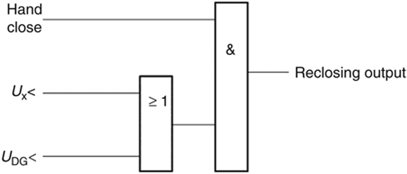
Figure 4.7 No-voltage grid-connection logic.
See Figure 4.8 for the schematic diagram of synchronization-based grid connection logic, where “Ux >” and “UDG >” represent nonzero voltage, and a time delay of 4 s is for confirmation of voltage stability.

Figure 4.8 Synchronization-based grid-connection logic.
After the microgrid is reconnected to the grid, the loads and DG previously taken out of the system are gradually reconnected to the system, and the microgrid enters the grid-connected mode. Figure 4.9 shows the flowchart of transfer from islanded mode to grid-connected mode.

Figure 4.9 Flowchart of transfer from islanded mode to grid-connected mode.
4.3.2. Grid separation control
For transfer of a microgrid from grid-connected mode to islanded mode, quick and accurate islanding detection is a prerequisite. Currently, there are many islanding detection methods, from which a suitable one should be determined based on the specific conditions. Short-time unsmooth transfer or smooth transfer may be adopted, depending on whether the microgrid has loads that must be continuously powered.
4.3.2.1. Islanding of microgrid
The microgrid is a solution for the integration of DG to a distribution network. It changes the architecture of the distribution network and realizes bidirectional power flow. Traditionally, when the distribution system became unavailable, power supply to loads will be interrupted. With a microgrid, when the distribution system is out of service, the DG is expected to operate independently to power the loads. This is known as islanding, either intentional or unintentional, as shown in Figure 4.10. Intentional islanding means planned islanding with predetermined control strategies, and unintentional islanding means unplanned and uncontrollable islanding, which should be prevented.

Figure 4.10 Schematic diagram of islanding.
Unintentional islanding does not meet the utilities’ requirements on grid management. The status of an island system is unknown as it is not monitored by the utility and operates independently. Therefore, unintentional islanding is uncontrollable, poses high risks, and will cause the following problems:
1. Some lines that are considered to have been disconnected from all power sources may still be powered, endangering the maintenance personnel and consumers.
2. Normal closing of the grid is disturbed. When the DG in islanded operation is reconnected to the grid, the microgrid system may be asynchronous with the grid. In this case, when the circuit breaker is closed, it may be damaged and a high current may appear, thus damaging the DG, or even causing tripping of the grid.
3. The grid cannot control the voltage and frequency of the island system, thus causing damage to distribution equipment and loads. If, after islanding occurs, the DG cannot regulate its voltage and frequency and is not equipped with protection relay for limiting deviation, the voltage and frequency of DG will fluctuate remarkably, thus causing damage to distribution equipment and loads.
With the development of the microgrid and increasing penetration of DG, anti-islanding is essential. Anti-islanding is intended to prevent unintentional islanding. The key of anti-islanding is detection, which is the prerequisite for islanded operation of the microgrid.
4.3.2.2. Transfer from grid-connected mode to islanded mode
1. Unsmooth transfer
Given the relatively long time taken for the low-voltage (LV) circuit breaker at the PCC to operate, power supply will be lost during this time during the transfer from grid connection to islanding. This is the so-called unsmooth transfer.
In the case of grid failure or outage, if voltage and frequency of the grid-tie bus are found beyond the normal range, or an intentional islanding order is sent from the energy management system, the connection/separation controller quickly disconnects the circuit breaker at the PCC and initiates transfer of control mode of the main power source after unimportant loads (or DG, as the case may be) are disconnected from the microgrid. The main power source switches to U/f control from P/Q control to realize constant-frequency and constant-voltage output and ensure voltage and frequency stability within the microgrid.
In this process, the islanding protection of DG acts and the DG quits service. After the main power source initiates islanded operation and resumes supply to important loads, the DG will automatically connect to the system and start operation. If all DGs are started at the same time, the island system will suffer a high impact. Therefore, they should be started separately. The energy management system should increase their output gradually. As the output is on the increase, the loads previously shed should be connected until the loads or DG outputs are beyond further regulation, and generation and consumption reach a new balance, thus realizing fast transfer from grid-connected mode to islanded mode. See Figure 4.11 for the flowchart of unsmooth transfer from grid-connected mode to islanded mode.
2. Smooth transfer
For a microgrid placing a higher requirement on reliability, smooth transfer is preferred. For this purpose, a high-power solid-state switch (with a closing or opening time less than 10 ms) is required to make up for the slow turn-on or turn-off of the mechanical circuit breaker, and the structure of the microgrid needs to be optimized.
As shown in Figure 4.12, important loads, a proper amount of DGs, and the main power source are connected to a section of the bus that is connected to the microgrid bus through a static switch, thus forming a subsystem that can maintain energy balance at the instant of isolation from the grid. Unimportant loads are directly connected to the main grid through the circuit breaker at the PCC.
In grid-connected mode, the microgrid often exchanges a large amount of power with the grid. This is especially the case for a low-capacity microgrid, which is mainly supported by the grid. When the microgrid is isolated, there will be a high power deficit, requiring the circuit with the solid-state switch to achieve balance between important loads and power output of DGs within a very short time after islanding occurs. In islanded mode, the ES or microturbines with self-regulation capability are used to maintain frequency and voltage stability within the microgrid; therefore, their capacities should be determined considering their output, demand of important loads, and maximum and minimum possible output of DG. A solid-state switch permits smooth transfer of the microgrid from grid-connected mode to islanded mode, and downsizes the service area of the microgrid in islanded mode.
In the case of grid failure or outage, if the system detects that the voltage or frequency of the grid-tie bus is beyond the normal range, or an intentional islanding order is sent from the energy management system, the grid connection/separation controller rapidly disconnects the circuit breaker at the PCC and the solid-state switch. As the switch can be quickly opened and closed, the main power source can start quickly and power important loads after the switch is opened, thereby ensuring continuous power supply to important loads. After the LV circuit breaker and circuit breaker for unimportant loads at the PCC are opened, the static switch is closed, and with large-capacity DGs restoring to operation, supply for unimportant loads is resumed gradually. See Figure 4.13 for the flowchart of smooth transfer from grid-connected mode to islanded mode.

Figure 4.11 Flowchart of unsmooth transfer from grid-connected mode to islanded mode.

Figure 4.12 Structure of microgrid using a solid-state switch.

Figure 4.13 Flowchart of smooth transfer from grid-connected mode to islanded mode.
4.4. Operation
A microgrid may operate in grid-connected mode or islanded mode. Grid-connected operation means that the microgrid is connected to the distribution network at the PCC and exchanges power with it. When load is greater than the DG output, the microgrid absorbs power from the distribution network; otherwise, the microgrid injects the excess power to the distribution network.
4.4.1. Grid-connected operation
Grid-connected operation can realize economic and optimal dispatch, central dispatch by the distribution network, automatic voltage and reactive power control, and forecast of intermittent DG output, loads, and power exchange. See Figure 4.14 for the flowchart of grid-connected operation.
1. Economic and optimal dispatch: A microgrid in grid-connected operation is aimed at maximizing energy efficiency (i.e., to utilize renewable energy as practical as possible) across the system under the premise of security, and to shift loads by means of charge and discharge of ES and time-of-use tariff.
2. Central dispatch by the distribution network: The centralized control layer of microgrid interacts with the distribution network dispatch layer in real time, and sends the microgrid status (connected or disconnected) and amount of power exchange at the PCC to the dispatch center, and acts according to control over the microgrid status and power exchange setting by the dispatch center. When an order is received from the dispatch center, the centralized control layer regulates the DG output, ES, and loads to maintain balance of active power and reactive power. Central dispatch by the distribution network can be achieved by setting the power exchange curve either in the microgrid management system or according to the remote orders from the distribution network dispatch automation system.
3. Automatic voltage and reactive power control: The microgrid can be deemed as a controllable load with respect to the grid. In grid-connected mode, the microgrid is not allowed to participate in management of grid voltage, and it manages its power factor under a uniform power factor, and manages the bus voltage within the microgrid to some extent by regulating the reactive power compensation equipment and reactive output of DG.
4. Forecast of intermittent DG output: Short-time DG output can be forecast according to the weather information released by the meteorological bureau, historical meteorological information, and historical records of DG outputs.
5. Load forecast: The demand of various loads, including total loads, sensitive loads, controllable loads, and interruptible loads within a short period can be forecast according to historical records.
6. Forecast of power exchange: Power exchange through the common circuits can be forecast based on forecast of DG output and loads and preset charge and discharge curves of ES.
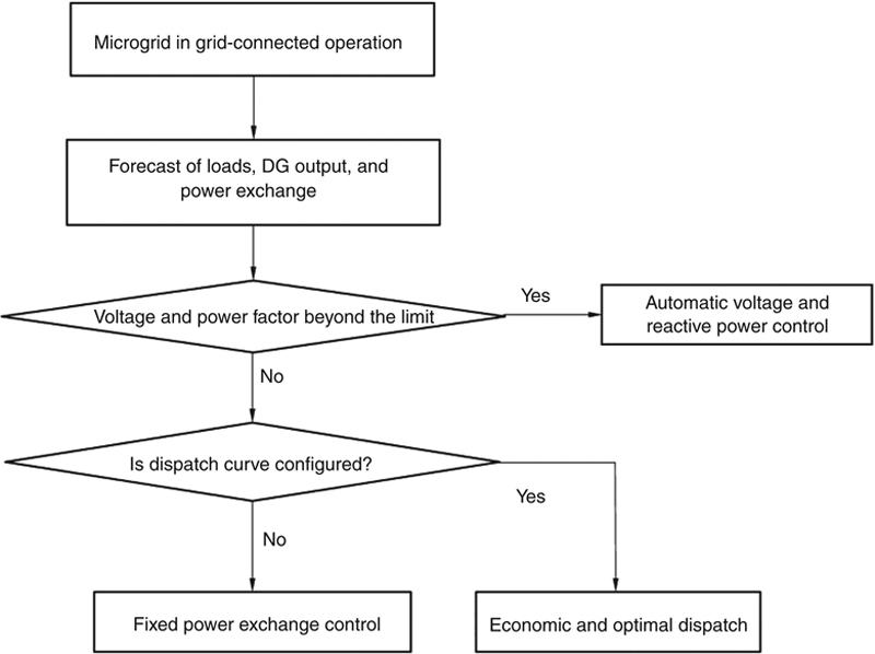
Figure 4.14 Flowchart of grid-connected operation.
4.4.2. Islanded operation
Islanded operation is mainly intended for stability of the microgrid and for continuous power supply to as many loads after the microgrid is separated from the main grid. See Figure 4.15 for the flowchart of islanded operation.
1. Load shedding in case of under-frequency or under-voltage: Fluctuation of load or DG output beyond the compensation capacity of ES may result in a drop of system frequency and voltage. When they drop below the settings, unimportant loads will be shed to prevent frequency collapse and voltage collapse.
2. Generator tripping in case of over-frequency or over-voltage: Fluctuation of load or DG output beyond the compensation capacity of the ES may result in a rise of system frequency and voltage. When they rise above the settings, the output of some DGs will be limited until the system frequency and voltage fall back to the normal range.
3. Control in case of relatively high DG output: In the case of high DG output, some loads previously shed can be reconnected to consume the excess power.
4. Control in case of excessive DG output: If DG output is excessive, and the system frequency and voltage are very high even though no loads are shed and all ESs are fully charged, the DG will quit service and loads are powered by the ES for a certain time, and then the DG is brought back to service.
5. Control in case of deficient DG output: If the dispatchable DG has been producing maximum output, and the SOC of ES is below the lower limit, unimportant loads will be shed to ensure continuous supply to important loads as long as possible.

Figure 4.15 Flowchart of islanded operation.
..................Content has been hidden....................
You can't read the all page of ebook, please click here login for view all page.