
Chapter 8
Earthing of a microgrid
Abstract
Earthing of a microgrid, introduces microgrid-earthing schemes.
Keywords
protective earthing
N conductor
PE conductor
TN system
neutral point
exposed conductive part
PEN conductor
residual current device (RCD)
displacement of neutral point
main equipotential bonding (MEB)
Earthing is one of the most widely used electrical safety measures in daily industrial production, work, and life. Users are generally unfamiliar with earthing protection measures. Any problem in earthing of the distribution system may pose a threat to the safety of personnel and equipment. There are two kinds of earthing, namely, functional earthing and protective earthing. Functional earthing includes working earthing, logic earthing, signal earthing, and shield earthing. Protective earthing means connecting a part of the electrical equipment to the earth by an earthing device to ensure the safety of personnel and equipment. This chapter discusses protective earthing, which, by securely earthing the electrical equipment, ensures the safety of personnel and equipment.
8.1. Secure earthing of low-voltage distribution network
Providing system earthing and protective earthing through conductors can ensure safety and provide protection. System earthing means the earthing of a point (generally the neutral point) of the power source, and protective earthing means earthing of electrical equipment, electrical installation or system. Two kinds of conductors are used, namely, a neutral conductor (represented by N) and a protective conductor (represented by PE). The former is connected with the system neutral point and can transmit electricity. It is a neutral line and working line, also called “zero wire” in single-phase systems. The latter, commonly known as “earth wire,” is used to earth the exposed conductive part of electrical equipment. Without the former, single-phase equipment cannot work normally; without the latter, equipment can be functional while its enclosure may be energized. The PE conductor can prevent electric shock.
As stated in GB 14050-2008 Types and Safety Technical Requirements of System Earthing, the earthing of 380/220 V AC low-voltage (LV) distribution systems is mainly in three forms, namely, TN, TT, and IT, and TN is further divided into three forms, namely, TN-C, TN-S, and TN-C-S (a total of five forms).
The meanings of these letters are as follows: The first letter indicates the relation between the power source and the earth, specifically, T means that a point (usually the neutral point) of the power source is directly earthed, I means that the power source is isolated from the earth or a point of the power source is directly earthed via a high impedance; the second letter indicates the relation between the exposed conductive part of electrical installation and the earth, specifically, T means that the exposed conductive part is directly earthed (irrelevant to earthing of the power source), and N means that the exposed conductive part is connected to the earthed neutral point of the power source; the third and fourth letters indicate the relation between N conductor and PE conductor, specifically, C indicates the combination of the two, and S indicates separation of the two.
8.1.1. TN earthing system
TN earthing is a prevailing form in China. In a TN earthing system, the neutral point of the power source is directly earthed, and the exposed conductive part of power-consuming equipment is connected to the N conductor via PE conductor.
The advantage of TN earthing is that when a single-line-to-earth short circuit occurs due to contact of a phase line of electrical equipment with the enclosure or due to damage of insulation of the equipment, and the fault current rises, overcurrent protection will act to instantaneously cut off the power. Ideally, when such a fault occurs, the fuse on the source side will break and the LV circuit breaker will trip instantly, thus disconnecting the faulty equipment from the power source, shortening the duration of hazardous touch voltage, and improving security. In addition, TN earthing requires fewer materials and work time and is used in a wide range of applications. Currently, it is widely used in China. In the case of no neutral point, or when the neutral point is not led out, a phase on the secondary side of the transformer may be earthed instead. Depending on the relation between the N conductor and PE conductor, TN earthing can be divided into three forms, respectively, TN-C, TN-S, and TN-C-S.
1. TN-C earthing system
Figure 8.1 shows the schematic diagram of a TN-C earthing system, in which the N conductor and PE conductor are combined as PEN conductor. Such a system is traditionally called a three-phase four-wire system.
Its main advantages include reducing a conductor, plus simple installation and saving of costs.
However, it also has several disadvantages. When the PEN conductor is disconnected, an earthing fault will occur, the enclosure of the electrical equipment will be charged with a 220 V voltage, and thus pose hazards; as the PEN conductor cannot be disconnected, it is hard to make electrical isolation during maintenance; when a current flows through the PEN conductor, a voltage drop will occur, leaving a potential difference between the enclosure of the equipment connected with the conductor and the earth, which may interfere with the communication device or cause explosion in an explosive atmosphere.
Note: In the event of an earthing fault, the magnetic field of the current flowing through the PEN conductor affects correct operation of the residual current device (RCD), and poses hazards for preventing disconnection of the PE conductor. Therefore, repeated earthing shall be made, which, however, will easily cause displacement of the neutral point. For this reason, the PE conductor or repeated earthing system of loads should be connected to the PEN conductor on the power source side of RCD, as shown in Figure 8.2.
2. TN-S earthing system
Figure 8.3 shows the schematic diagram of a TN-S earthing system, in which the N conductor and PE conductor are separated. This system is traditionally called a three-phase five-wire system.
Its main advantages are high security and reliability. In the case of load unbalancing, there will be unbalanced current flowing through the N conductor while the PE conductor is not affected and has no potential to the earth. There is fault current flowing through the PE conductor only in contact with the enclosure, and normally, the exposed conductive part of the electrical equipment has zero potential to the earth; the switches at four levels can disconnect L1, L2, L3, and N conductors as necessary, thus making electrical isolation possible during maintenance.
However, a separate PE conductor needs to be erected all the way, requiring a high initial investment.
Note: The PE conductor must not be disconnected, but can be earthed repeatedly; the RCD may be used for preventing electrical shock and lightning strike, and the N conductor should in no case be earthed repeatedly.
3. TN-C-S earthing system
Figure 8.4 shows the schematic diagram of a TN-C-S earthing system, in which the N conductor and PE conductor are combined (TN-C earthing) before the entry point into the building, and are separated (TN-S earthing) after the entry point into the building. Such a system is traditionally called a local three-phase five-wire system.
For this system, it is unnecessary to erect a special PE conductor from the power source to the consumers’ equipment. Although all conductive parts are interconnected at the entry point (i.e., main equipotential bonding, or MEB for short), and that the PEN conductor is split into separate PE conductor and N conductor after the entry point, no voltage drop appears in the PE conductor, and the entire electrical installation has zero potential to the earth. To sum up, such a system is free of the hazards that may arise in a TN-C earthing system and has a security level as a TN-S earthing system.
However, the voltage drop along the PEN conductor increases the voltage of the entire electrical installation to the earth. The amplitude of the voltage depends on the unbalanced current through the line and length of the line before combination. The more unbalanced the loads and longer the line before combination, the greater the displacement of the equipment enclosure-to-earth voltage. Therefore, the unbalanced current of loads is required to be within a certain range.
Note: The PE conductor shall be earthed repeatedly to prevent hazards resulting from disconnection of the conductor, which, however, may easily cause displacement of the neutral point.
Whether in a TN-C, TN-S, or TN-C-S earthing system, the fault voltage appearing on the PE conductor or PEN conductor will spread among various electrical installations energized by the same power source. Therefore, MEB shall be made to prevent any accident due to spreading of the fault voltage. For this reason, TN earthing should not be used in occasions without MEB such as street lights, construction sites, or agricultural applications.

Figure 8.1 Schematic diagram of a TN-C earthing system.
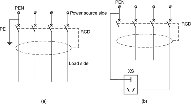
Figure 8.2 RCD in a TN-C earthing system.
(a) Repeated earthing and (b) PE conductor.
(a) Repeated earthing and (b) PE conductor.

Figure 8.3 Schematic diagram of a TN-S earthing system.

Figure 8.4 Schematic diagram of a TN-C-S earthing system.
8.1.2. TT earthing system
Figure 8.5 shows the schematic diagram of a TT earthing system, in which the neutral point of the power source is directly earthed, and the N conductor is led out to constitute a three-phase four-wire system; the exposed conductive parts of power-consuming equipment are separately earthed via their respective PE conductors, thus realizing electrical isolation with system earthing.

Figure 8.5 Schematic diagram of a TT earthing system.
The PE conductors of the exposed conductive parts of electrical installation are isolated from system earthing and independent of each other. Normally, the exposed conductive parts have a zero potential to the earth, and the fault voltage appearing on the power source side or various power-consuming equipment will not spread.
In the event of three-phase load unbalance after disconnection of the N conductor, potential drift of the neutral point will occur, causing voltage rise on a phase and thus burning of single-phase equipment; in the event of earthing fault, the fault current can return to the power source via the protective earthing resistor and system earthing resistor, and due to the resistance, the fault current is relatively small, thus failing to initiate overcurrent protection, and making the setting of overcurrent protection much more complicated.
Note: In the event of earthing fault, the fault current is relatively small due to the earthing resistance, and thus the LV automatic switch may fail to isolate the fault quickly, leaving a voltage on the enclosure of equipment. Therefore, an RCD is required for prevention against electric shock and lightning strike.
8.1.3. IT earthing system
Figure 8.6 shows the schematic diagram of an IT earthing system, in which the power source is not earthed or earthed via an impedance, the live parts on the power source side are insulated from the earth or earthed via a high impedance, the exposed conductive parts of electrical equipment are directly earthed, and the metallic enclosures of power-consuming equipment are directly earthed or connected to the earthing electrode of the power source via PE conductor.

Figure 8.6 Schematic diagram of an IT earthing system.
It has the following advantages: in the case of a single earthing fault, due to the lack of a circuit for the fault current to return to the power source, the fault current is just a capacitive current to earth of the healthy phase and very small, and therefore, the fault voltage to the earth is very low and will not cause electric shock, explosion, or fire. Therefore, IT earthing is applicable to special occasions with high electrical hazards. Furthermore, in the case of a single earthing fault, it is not necessary to disconnect the power source to interrupt power, thus making IT earthing very suitable for electrical installations having a high requirement for uninterrupted power supply.
In this system, no N conductor is led out to provide 220 V power supply for single-phase equipment; in the case of single-phase-to-earth faults, the voltage of the other two phases will rise to a 380 V line voltage from a 220 V phase voltage, posing a greater threat to personal safety.
Note: Single-phase-to-earth fault is hard to detect; load unbalance will result in displacement of the neutral point. To detect single-phase-to-earth fault, an insulation monitoring device or single-phase earthing protection shall be provided to give audio and visual signals when a fault occurs to remind the operators to isolate the fault in time; otherwise, the fault will develop into two-phase-to-earth fault if earthing fault occurs in another phase, which will cause interruption of the power supply.
In view of the advantages and disadvantages of each individual earthing system, it is concluded that, in determining the earthing mode of an LV distribution system, TN-C earthing should be selected with due care; for a building with a substation, TN-S earthing is preferred, while for a building without a substation and with an LV power supply, TN-C-S earthing in conjunction with MEB should be employed; for an outdoor place without MEB, TT earthing should be employed in conjunction with RCD; for a place having a high requirement on power reliability and with inflammable and explosive materials, IT earthing should be employed.
8.2. System earthing of a microgrid
8.2.1. Requirements for earthing of microgrid
Grid-connection of distributed resources (DRs) should follow the requirements in Q/GDW 480-2010 Technical Rules for Distributed Resources Connected to Power Grid, specifically, the earthing mode of DRs shall be consistent with that of the grid, and can ensure personnel and equipment safety and protection coordination. IEEE 1547 IEEE Standard for Interconnecting Distributed Resources to Electric Power Systems specifies the basic principles for earthing of the microgrid as follows: the earthing mode of DRs should not cause overvoltage of equipment within the microgrid and affect coordination of protections. For distributed generation (DG) that is connected to the distribution network not as a microgrid, it is usually connected with the neutral point not earthed.
Depending on the earthing mode of the LV distribution system, the microgrid can adopt three earthing modes: (1) the neutral point of DG is not earthed and the N conductor is not led out, (2) the neutral point of DG is not earthed but the N conductor is led out, (3) and the neutral point of DG is earthed. The earthing mode of the microgrid should be properly determined for different earthing systems.
8.2.2. Earthing mode of DG in a TN or TT earthing system
If, in a TN or TT earthing system, the neutral point of DG is not earthed and the N conductor is not led out, a 220 V voltage cannot be provided for single-phase loads in islanded operation, as shown in Figure 8.7a. While if the neutral point of DG is earthed, as shown in Figure 8.7c, in grid-connected operation, a small proportion of the three-phase unbalanced current will return to the power source not via the N conductor as it is supposed to but via an unexpected circuit. This proportion of current is called stray current. This stray current will be high if there are multiple DGs or if the transformer and DG are located in the same building. This may result in the following accidents:
1. Fire: The stray current may ignite combustible materials if the circuit is poorly conductive.
2. Corrosion of underground metallic parts: If returning to the power source through the earth circuit, the stray current may cause corrosion of underground metallic pipelines or foundation reinforcement.
3. Interference of magnetic fields: The power distribution circuit and the stray current-to-power source circuit may form a closed ring. The magnetic fields within the ring may cause interference to the highly sensitive communication equipment within the ring.

Figure 8.7 Earthing mode of DG in a TN or TT earthing system.
(a) N conductor not led out, (b) N conductor led out, and (c) neutral point earthed.
(a) N conductor not led out, (b) N conductor led out, and (c) neutral point earthed.
IEC 60364 – 1: 2005 Low-voltage Electrical Installations–Part 1: Fundamental Principles, Assessment of General Characteristics, Definitions, IEC 60364 – 4-444 Electrical Installations of Buildings–Part 4: Protection for Safety Section 444: Protection against Electro-Magnetic Interferences (EMI) in Installations of Buildings and China’s standard GB/T 16895.1 – 2008 Low-voltage Electrical Installations–Part 1: Fundamental Principles, Assessment of General Characteristics, Definitions all stipulate that a multisource system shall be earthed only at one point, to avoid any unwanted stray current circuit due to improper earthing (see Figure 8.8). The following lists the requirements:
1. The neutral points of transformers or the star points of generators should not be directly connected to the earth.
2. The conductor interconnecting the neutral points of transformers or star points of generators should be insulated and not be connected with power-consuming equipment.
3. The conductor interconnecting the neutral points of power sources shall be connected with the PE conductor only at one point and within the main distribution panel.
4. The PE conductor connecting to the electrical installation may be provided with additional earthing device.
5. No extension of the system should affect the normal functions of protection measures.

Figure 8.8 Earthing of a multisource system.
In conclusion, in a TN or TT earthing system, the DGs may be earthed in such a way that the neutral point is not directly earthed, and the N conductor is led out and earthed at one point within the LV main distribution panel, as shown in Figure 8.7b.
8.2.3. Earthing mode of DG in an IT earthing system
In an IT earthing system, all live parts are isolated from the earth, and the exposed conductive parts of the electrical installation are separately earthed. The integration of DGs should not change the original earthing mode. If in an IT earthing system, the neutral point of DG is earthed as shown in Figure 8.9c, IT earthing will become TN or TT earthing, which is worse than IT earthing in terms of power reliability and security.

Figure 8.9 Earthing of DG in an IT earthing system.
(a) N conductor not led out, (b) N conductor led out, and (c) neutral point earthed.
(a) N conductor not led out, (b) N conductor led out, and (c) neutral point earthed.
In an IT earthing system, the N conductor is generally not led out, and in this case, the N conductor of DG may not be led out either, as shown in Figure 8.9a; while if the N conductor in an IT earthing system is led out, the N conductor of DG may be also led out, as shown in Figure 8.9b, to ensure safety and reliability in grid-connected operation and islanded operation.
..................Content has been hidden....................
You can't read the all page of ebook, please click here login for view all page.