
Chapter 5
Protection of the microgrid
Abstract
Protection of the microgrid, discusses impacts of connection of microgrids on distribution network relay protection, microgrid protection strategies, and configuration scheme of protection for microgrids connected to distribution networks.
Keywords
relay protection
fault characteristics
common distribution network
protection configuration
effects on relay protection
three-phase short circuit
two-phase short circuit
single phase to ground fault
protection strategy
differential protection
packet transport network
back-up protection
forward impedance relay
reverse impedance relay
operation protection
islanding protection
overcurrent protection
synchronous grid connection
The same as a traditional electric power system, a microgrid is required to operate securely and stably and its relay protection should provide reliability, response speed, flexibility, and selectivity. When the microgrid is grid-connected, power can flow bidirectionally between the distribution network and the microgrid, different from the unidirectional flow found in traditional distribution networks. In addition, different from traditional rotating generators, the microgrid is flexibly connected to the grid based on power electronic technologies, which brings a difference to the relay protection.
5.1. Special fault characteristics of DG
Different types of distributed generation (DG) sources are integrated to the grid in different modes:
1. DC sources: power sources producing direct current, including fuel cells, photovoltaic (PV) cells, and DC wind turbines. These sources are integrated to the grid via inverters, as shown in Figure 5.1a.
2. AC–DC–AC sources: power sources producing alternating current not at power frequency, including AC wind turbine and single-shaft microturbine. The alternating current needs to be converted to direct current and then back to alternating current before being delivered to the grid, as shown in Figure 5.1b.
3. AC sources: producing stable alternating current at power frequency, including asynchronous wind turbines and small synchronous generators. These sources are directly integrated to the grid without using any power electronic inverters, as shown in Figure 5.1c.
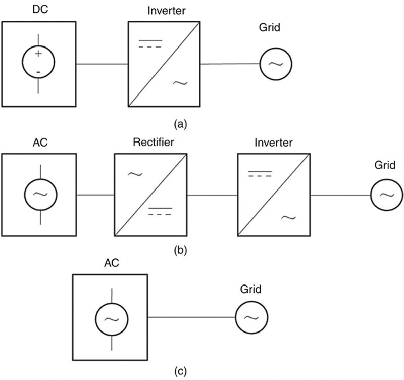
Figure 5.1 Schematic diagrams of DG sources connected to the grid.
(a) DC sources, (b) AC–DC–AC sources, and (c) AC sources.
(a) DC sources, (b) AC–DC–AC sources, and (c) AC sources.
As stated, DG sources are connected to the grid either directly or via inverters, with the latter more often used.
Inverters are under either P/Q or U/f control. In grid-connected operation, all DGs are under P/Q control; in islanded operation, the master DG is under U/f control while the slave DGs are under P/Q control.
For inverters under P/Q control, the output current when a fault occurs should not be higher than 1.5In according to Q/GWD 147 – 2010 Technical Specifications for Interconnecting PV Stations with Grid and CGC/GF 001:2009 Technical Requirements and Test Methods for Inverters Exclusively for Integrating PV Power to the Grid. In the case of the three-phase short circuit, if the fault current is smaller than 1.5In, the inverter is a constant-power source, the current rises, and the voltage drops; if the fault current is equal to 1.5In, the inverter is a constant-current source, and after its protection acts, the inverter automatically quits service. In the case of asymmetric short circuit, the inverter is a constant-power positive sequence source, and the current rises; in the case of two-phase short circuit, the negative sequence voltage rises; and in the case of single-phase-to-earth fault, the zero sequence voltage rises.
For inverters under U/f control, in the case of the three-phase short circuit, the inverter is a constant-voltage constant-frequency source, and if the output power has not reached the maximum, the current rises and the output power increases; and if the output power has reached the maximum, the voltage drops and the undervoltage protection of the inverter acts; in the case of asymmetric short circuit, the inverter is a constant-power positive sequence source, and the current rises; in the case of two-phase short circuit, the negative sequence voltage rises; and in the case of single-phase-to-earth fault, the zero sequence voltage rises.
5.2. Effects of microgrid on relay protection of the distribution network
5.2.1. Protection of a traditional distribution network
A traditional distribution network is a 10 kV network in one-way radial pattern or in hand-in-hand open-loop pattern.
Figure 5.2a shows a one-way radial distribution network, which is generally provided with traditional three-stage current protections, respectively current quick-break protection, specified time current quick-break protection, and specified time overcurrent protection. The protection is set as follows: current quick-break protection is set based on the maximum short-circuit current following a three-phase short-circuit fault at the end of the line and cannot protect the entire line; specified time current quick-break protection is set based on the operating current of current quick-break protection for components of the neighboring line and can protect the entire line; specified time overcurrent protection is set based on the maximum load current of the line, serves as the backup for the protection of the neighboring line, and can protect the entire line. For nonterminal lines, three-stage current protection and other line protections are used together. The protection for terminal lines is simplified, generally including current quick-break protection (set to avoid the maximum three-phase short-circuit current appearing on the low-voltage (LV) side of the step-down transformer at the line end) and specified time overcurrent protection (set to avoid the maximum load current, with a time delay of 0.5 s). Cable lines mostly experience permanent faults and are not provided with reclosing function; while overhead lines are generally provided with this function.

Figure 5.2 Patterns of distribution network.
(a) One-way radial network and (b) hand-in-hand loop network.
(a) One-way radial network and (b) hand-in-hand loop network.
Figure 5.2b shows a hand-in-hand loop network, in which the automatic circuit recloser realizes automatic distribution, and the stage current protection, automatic circuit recloser, and sectionalizer work together to isolate the faults. When a fault occurs on a line, the circuit breaker trips off and the voltage of the line is lost. When voltage loss is detected, all sectionalizers will open. When the circuit breaker is reclosed for the first time, the automatic circuit reclosers will switch in stage by stage according to the predefined time delays. When it comes to the fault section, the circuit breaker trips off again and the switches on both sides of the faulty section will detect fault voltage and block. Then, after the circuit breaker recloses again, the normal section will resume normal operation while the faulty section is isolated.
5.2.2. Protection of a traditional LV distribution network
An LV distribution system operates at 0.4 kV (380/220 V) and is usually provided with an LV circuit breaker (also called universal circuit breaker) with relay protection, fuse protection, and hot relay protection. According to GB 10963.1 – 2005/IEC 60898 – 1:2002 Circuit-breakers for Overcurrent Protection for Household and Similar Installation-Part 1: Circuit-breakers for a.c. Operation, there are three types of instantaneous current tripping: (1) the tripping range of type B is 3In–5In, (2) type C 5In–10In, and (3) type D 10In–20In, and quick-break tripping time shall be less than 0.l s. The time delay of action following a short-circuit has an inverse time feature, the conventional tripping current is 1.45In, and the tripping time is less than l h (In < 63 A) or 2 h (In > 63 A).
5.2.3. Impacts of microgrid on relay protection of distribution network
A traditional distribution system is a radial one-end-source system, which requires no directional element for feeder protection, and is mostly provided with three-stage current protection. After a microgrid is connected to the distribution network, when a fault occurs, the DG sources in the microgrid, in addition to the system, also contribute to the fault current, forming a multisource system and changing the short-circuit current level on a node. The type, location, and capacity of the DG sources affect the operation of relay protection of the distribution network.
The integration of a microgrid to a one-way radial distribution network mainly affects the distribution network in the following ways: reduction of sensitivity of infeed current protection for the line end; undesired operation of fault protection of neighboring lines; and reclosing failure. The following gives a detailed analysis on the impacts of the microgrid on relay protection of the distribution network when the microgrid is connected to the distribution network at different points.
1. At the end of the feeder: As shown in Figure 5.3, DG is integrated to the distribution network at the feeder end. When a fault occurs on point kl on the neighboring line L2, the fault current may flow from the DG to k1, causing the protections 1, 2, and 3 of L1 to operate falsely.
2. In the middle of the feeder: As shown in Figure 5.4, the DG is integrated to the distribution network in the middle of the feeder. Similarly, when a fault occurs at point k1 on the neighboring line L2, the fault current may flow from DG to k1, causing the protection 3 of L1 to operate falsely; when a fault occurs at point k2 on L1, due to the infeed current produced by DG, the sensitivity of protection 3 is reduced, probably causing failure of operation, and therefore, the branch coefficient needs to be recalculated. With the DG connected to the distribution network, protection 2 needs to be reset based on the maximum operation mode. When protection 2 operates, the arc cannot be extinguished, causing reclosing failure of protection 2.
3. At the head of the feeder: As shown in Figure 5.5, the DG is integrated to the distribution network at the head of the feeder. In this case, all protections need to be reset based on the new maximum operation mode.

Figure 5.3 DG integrated to the distribution network at the feeder end.

Figure 5.4 DG integrated to the distribution network in the middle of feeder.

Figure 5.5 DG integrated to the distribution network at the head of feeder.
In a hand-in-hand loop distribution network, the automatic circuit recloser is used for automatic power distribution, and the stage current protection works together with the automatic circuit recloser and sectionalizer to isolate the faults. However, due to the presence of DG, when a fault occurs, the line still has a voltage, and thus the sectionalizer will not open, the fault cannot be isolated, and the backup power source cannot serve the normal section.
5.2.4. Impacts of a microgrid on protection of traditional LV distribution lines
Figure 5.6 shows the current path of load circuit in a microgrid system, in which  represents the potential of the microgrid system,
  the potential of DG sources, PCC the point of common coupling,
  the voltage at the PCC, Zf loads of the microgrid, and
  load currents. In normal grid-connected operation, and jointly provide the load current; and in islanded operation, alone provides the load current.

Figure 5.6 Path of load current in a microgrid system.
Figure 5.7 gives a complex sequence network diagram for various faults based on the method of symmetrical components, where  represents the potential of the power source, and Z0, Z1, and Z2 the zero-sequence impedance, positive-sequence impedance, and negative-sequence impedance, respectively. In grid-connected operation, is equivalent to the sum of the grid source and DG source , and in islanded operation, is the DG source . Fault current analysis involves three-phase short circuit, two-phase short circuit, and single-phase-to-earth fault.

Figure 5.7 Complex sequence network diagram of various short circuits.
(a) Three-phase short circuit, (b) two-phase short circuit, and (c) single-phase short circuit.
(a) Three-phase short circuit, (b) two-phase short circuit, and (c) single-phase short circuit.
5.2.4.1. Three-phase short circuit
Figure 5.8 is a diagram of the three-phase short circuit. Taking short circuit in phase U as an example, it can be inferred from Figure 5.7a that
 (5.1)
(5.1)where Z1S is the positive sequence impedance of power source, and Z1L the positive sequence impedance of line.

Figure 5.8 Diagram of three-phase short circuit.
5.2.4.2. Two-phase short circuit
Figure 5.9 is a schematic diagram of the two-phase short-circuit. Taking short circuit in phases V and W as an example, it can be inferred from Figure 5.7b that

where Z1 = Z1S + Z1L, Z2 = Z2S + Z2L

Figure 5.9 Diagram of two-phase short circuit.
As Z1 is approximately equal to Z2, then
 (5.2)
(5.2)5.2.4.3. Single-phase-to-earth fault
Figure 5.10 is a diagram of single-phase-to-earth fault. Taking short circuit in phase U as an example, it can be inferred from Figure 5.7c that
where Z1 = Z1S + Z1L, Z2 = Z2S + Z2L, and Z0 = Z0S + Z0L, and Z1 is approximately equal to Z2, then
 (5.3)
(5.3)
Figure 5.10 Diagram of single-phase-to-earth fault.
For overhead lines, Z0 = 2Z1, then
 (5.4)
(5.4)For cable lines, Z0 = 3.5Z1, then
 (5.5)
(5.5)It can be seen that the three-phase short-circuit current is the greatest, followed by two-phase short-circuit current (0.87 times the three-phase short-circuit current) and single-phase-to-earth fault current (0.55 or 0.75 times the three-phase short-circuit current).
To carry out the above analysis and calculation, the impedance of the section from the location of protection to the equivalent power source, and the impedance of the section from the location of protection to the fault point should be identified. As the equivalent parameters of DG are hard to define, the short-circuit capacity method is used here to calculate the short-circuit currents in grid-connected operation and islanded operation.
In grid-connected operation, the grid source operates in parallel with the DG source , and the short-circuit capacity of the distribution transformer is
 (5.6)
(5.6)where U1k% is the short-circuit impedance (short-circuit voltage), and S1N the capacity of the distribution transformer.
The short-circuit current provided by is
Assuming that the overcurrent protection of inverters acts once the current rises above 1.5 times the rated current, the short-circuit capacity of is
where S2N is the capacity of .
The short-circuit current provided by is
The maximum short-circuit current in grid-connected operation Ik = I1k + I2k.
In islanded operation, alone serves the loads, and the maximum short-circuit current Ik is equal to I2k.
For instance, in Figure 5.6, is a 10 kV distribution network connected with a distribution transformer with a capacity (S1N) of 800 kVA, the short-circuit impedance Uk% is 4%, the voltage of LV bus, U is 400 V, and the capacity of the DG source (S2N) is 600 kVA.
The maximum short-circuit current in grid-connected operation is

The maximum short-circuit current in islanded operation is
The short-circuit current in grid-connected operation, mainly provided by the power source of the distribution network, is much greater than that in islanded operation. In grid-connected operation, when a fault occurs on the LV distribution network, the system source and DG source contribute to the fault current, and therefore, the fault current is greater than that produced solely by the system source. In islanded operation, when a fault occurs on the LV distribution network, the DG alone provides the fault current, which is relatively small. In addition, in islanded operation, the output current of inverters is limited within 1.5In following a fault on the distribution network, the tripping time of a traditional LV circuit breaker with relay protection is nearly 1 h (In < 63 A), and thus the fault cannot be isolated rapidly.
5.3. Microgrid operation and protection strategies
Microgrid protection is required to deal with the influence caused on the traditional distribution system by integrating the microgrid and meeting the requirement for protection brought by islanded operation. The integration of multiple DGs and energy storage (ES) changes the fault characteristics of the distribution system, and makes the variation of electrical variables very complicated in the case of a fault. The traditional protection principles and fault detection methods may fail to correctly locate the fault. Proper operation and protection strategies are the key to reliable operation of the DG system. As the microgrid is intended for grid-connected operation and islanded operation, its protection and control are very complicated. According to current practices, control and protection are a core microgrid enabling technology.
Before the concept of microgrid was introduced, the DGs integrated to the distribution network were not allowed to operate independently. Hence, besides the basic protection functions, the inverters should be able to prevent the occurrence of islanding, and automatically take the DGs out of service following a fault. The main protection strategies are as follows:
1. The DG is automatically taken out of service following a fault on the distribution network and the protection of the distribution network is not affected.
2. The capacity and PCC of DG are limited and the distribution network remains unchanged.
3. Measures for limiting the fault current are taken, for example, a fault current limiter is used to minimize the effects of DG after a fault occurs, and the distribution network remains unchanged.
A microgrid should be able to operate in parallel with the grid and in islanded mode. It shall meet the following basic requirements:
1. In grid-connected operation, if a fault occurs on the microgrid, the microgrid protection should operate reliably to clear the fault. For example, when the electrical equipment in the LV distribution network fails, the protection of the distribution network should operate to remove the equipment to ensure secure and stable operation of the microgrid.
2. When an instantaneous fault occurs on the distribution network, the protection of the distribution network should operate quickly to clear the fault to maintain uninterrupted operation of the microgrid.
3. In the case of power loss of the distribution network, the islanding protection of the microgrid operates to isolate the microgrid from the distribution network and the microgrid switches to islanded operation.
4. In islanded operation, when a fault occurs on the microgrid, the protection should operate reliably to clear the fault to ensure secure and stable operation of the microgrid;
5. Upon recovery of the distribution network, the microgrid is reconnected to the grid.
5.4. Protection scheme for distribution network connected with a microgrid
5.4.1. Requirements of microgrid on primary equipment and relay protection of distribution network
In a traditional one-way radial distribution network, a circuit breaker is provided only at the power source end. While in a traditional hand-in-hand loop network, circuit breakers are provided at the power source end and the open-loop points, and sectionalizers are provided at other points. Since the sectionalizers are incapable of isolating faults, repeated reclosing operations are needed to isolate the fault. One purpose of the microgrid is to improve power reliability and quality, which requires quick fault isolation.
With the integrated microgrid, the traditional primary equipment in the distribution system cannot realize quick fault isolation, and therefore the following configuration is required:
1. Distribution networks at 10 kV or above should all be provided with a circuit breaker.
2. 0.4 kV LV distribution networks should be provided with a miniature circuit breaker supporting remote control.
3. The integration of the microgrid should not cause any change to the earthing pattern of the 0.4 kV LV distribution network.
4. In islanded operation, earthing of DGs should be considered.
5.4.2. Differential relay protection of the distribution network
To solve the problems caused by integration of the microgrid, the mature differential protection scheme for high-voltage (HV) systems is configured for the distribution network as the main protection and simple overcurrent protection is configured as backup. Theoretically, Kirchhoff’s law-based differential protection is the best scheme for the buses, lines, and transformers in substations. For this protection, only the currents on both sides of the protected object are collected and compared based on simple criteria and the protected object has a high sensitivity.
5.4.2.1. Main protection – differential protection
Figure 5.11 presents the protection for a distribution network containing multiple microgrids. A 10 kV distribution network can be divided into multiple areas based on the protected object, respectively, line differential protection area, bus differential protection area, and distribution transformer differential protection area, as shown in the figure. For the distribution transformer, the differential current should be calculated taking into account the effect of the Y→∆ or ∆→Y current compensation method. For other protection areas, if the forward current direction is presumed to be from bus to line, the differential current is the vector sum of currents on both sides.

Figure 5.11 Schematic diagram of protection for a distribution system containing multiple microgrids.
In differential protection, differential protection actuating criteria and percentage restraining criteria form an AND gate, as shown in Figure 5.12.

Figure 5.12 Block diagram of current differential protection.
The differential protection actuating criteria are
The percentage restraining criteria are
where, Id means the differential current,  ;
;  the setting value of the actuating criteria; Ir the restraining current,
  ; k the percentage restraining coefficient; and
  currents on both sides of the protected object.
The smart collection unit provided for the circuit breaker interacts with the differential protection through the Packet Transport Network (PTN) with the sampled value and Generic Object Oriented Substation Event (GOOSE) messages specified in IEC 61850. The IEEE 1588 clock synchronization protocol can realize a synchronization precision of 100 ns.
The IEC 61850 is the most complete standard on substation automation to date, and has been widely applied in smart substations. It defines GOOSE and switching Ethernet with priority and virtual local area network flag (IEEE 802·1Q), which ensure real-time transfer of messages. Using the multicast application association model based on the publisher/subscriber communication principles, the GOOSE communication mechanism is an effective solution for real-time data transfer from one data source to multiple receivers.
The IEEE 1588, a precision clock synchronization protocol for distributed measurement and control systems, was released in 2002 and has a precision of μs. In 2008, IEEE 1588 V2 was released, which further specified and optimized the precision, security, and redundancy. In the second and third revisions of IEC 61850, experts of the working group proposed to apply the IEEE 1588 protocol in the substation-wide automation system.
PTN is a new optical transmission network architecture. It provides a layer between IP services and optical transmission media at the bottom layer, and is designed to meet the requirements of sudden increase of packet services and statistical multiplexing. Although mainly intended for packet services, it also supports other service types. It helps reduce the overall cost while inheriting such traditional advantages of optical transmission as high availability and reliability, effective bandwidth management and traffic engineering, convenient operation administration and maintenance, scalability, and high safety. At present, clock synchronization based on IEEE 1588 V2 has been widely applied in PTN.
Differential protection is based on the three-layered structure described in Chapter 2. Figure 5.13 presents a diagram of the differential protection system based on three-layer control areas, respectively, the smart collection unit at the local control layer, differential protection at the centralized control layer, and distribution network dispatch system at the distribution network dispatch layer, consistent with the three-layer architecture of the microgrid control system. It best suits protection against and control of transient faults of independent microgrids. See Figure 4.1 “Schematic diagram of three-state control system of an independent microgrid” in Chapter 4. For reliability purposes, the differential protection at the central control layer is configured in duplicate.

Figure 5.13 Schematic diagram of central differential protection system based on three-layer control architecture.
The smart collection units at the local control layer have the following functions:
1. Collect the voltage and current at the installation points and switch position;
2. Receive and respond to the tripping and reclosing orders from the differential protection at the centralized control layer;
3. Provide back-up protection for equipment at the local control layer;
4. Send fault information and other operation information;
5. Provide back-up protection.
The differential protection at the centralized control layer has the following functions:
1. Receive sampled current values and status information sent from the smart collection units;
2. Determine the differential protection criteria based on sampled current values;
3. Provide circuit breaker failure protection;
4. Identify the faulty area and give tripping orders;
5. Send fault information to the distribution network dispatch layer.
The differential protection at the centralized control layer collects current and status information from all nodes of the distribution network. This is in nature a network-based differential protection and realizes quick and automatic fault location and isolation.
Differential protection is configured in duplicate, to prevent loss of protection of the entire system when the differential protection is out of service due to hardware failure. The two protection systems are both in service under normal conditions. When one of them fails and quits service, its logic judgment and tripping output are blocked, while the remaining one is not affected.
5.4.1.2. Back-up protection
In differential protection, circuit breaker failure protection is provided to make the neighboring circuit breaker operate and isolate the fault when a circuit breaker fails.
Distribution networks at 10 kV and above are provided with dual differential protection systems, ensuring high reliability, response speed, sensitivity, and selectivity. In addition to the highly reliable main protection, simple back-up protection, such as specific time-delay overcurrent or distance protection and directional overcurrent protection, may also be provided by making use of the smart collection units to prevent complete loss of protection of the distribution network when the central differential protection fails and quits service.
Local smart collection units are provided with back-up protection. Specifically, the local line collection unit is provided with distance or overcurrent protection as the back-up protection for lines and buses; the local transformer collection unit is provided with overcurrent protection as the back-up protection for transformers; the HV side of the distribution step-up transformer is provided with specific time-delay directional overcurrent protection (as illustrated in Figure 5.14a) as the back-up protection against internal faults of the transformer. It can also serve as the back-up protection for internal faults of the submicrogrids by setting it to prevent overcurrent flowing to the power source and be sensible to some extent to 0.4 kV bus faults. The distribution step-down transformer is configured with specific time-delay overcurrent protection as shown in Figure 5.14b, which is set based on the maximum load current.

Figure 5.14 Back-up protection for distribution transformers.
(a) Distribution step-up transformer and (b) distribution step-down transformer.
(a) Distribution step-up transformer and (b) distribution step-down transformer.
5.4.3. Protection of LV distribution network based on directional impedance relay
In the LV distribution network containing a microgrid, forward and reverse impedance relays are provided for feeder units with DGs as distance protection, in which the forward impedance relay operates without time delay and is used for protection of the outgoing line. The reverse impedance relay operates with a time delay of 0.5 s and is used for protection of the LV bus (see Figure 5.15). Other feeder units without DG (load lines) are provided with forward impedance relay as distance protection, which operates without time delay and is used for protection of the outgoing line (see Figure 5.16).

Figure 5.15 Feeder unit with DG.

Figure 5.16 Feeder unit without DG.
The impedance relays use an overcurrent-actuating member, are polarized with memory positive sequence voltage, and have biasing impedance characteristics considering the small angle of impedance for a 0.4 kV voltage class.
Criteria of current-actuated element
Criteria of the forward impedance relay
 (5.13)
Criteria of the reverse impedance relay
 (5.14)
where, for phase-to-phase impedance relay, 
 for phase-to-ground impedance relay,
 ; zset is the setting value of impedance, and θ is the deviation angle of impedance, which is −30°.
The forward impedance relay is set to avoid the maximum load. When phase-to-phase or phase-to-ground short circuit occurs on the line, it operates without time delay to trip the circuit breaker of this line.
The reverse impedance relay should be set to avoid the short-circuit current of the bus or the setting value of the current quick-break protection for the line end on the HV side of the transformer. It covers the transformer and sometimes part of the HV line and LV line. Its setting value is relatively small so as to avoid unintentional operation when short circuit occurs on the HV side. In the case of phase-to-phase or phase-to-ground short circuit on the LV bus, the reverse impedance relay of the feeder unit with DG operates with a time delay of 0.5 s to trip the circuit breaker of this line and disconnect the DG from loads. In the case of short circuit on the LV line, transformer or HV line, although the reverse impedance relay of this feeder unit operates, the 0.5 s time delay ensures no protection output and no tripping of the circuit breaker of this line; and when the fault is cleared, the relay is automatically recovered.
This distance protection is in service in islanded operation and in grid-connected operation. In islanded operation (the microgrid is separated from the grid at the PCC), it is the sole protection for the microgrid. In grid-connected operation, it can also trip the circuit breaker of the 0.4 kV LV distribution system.
Figure 5.17 shows an analysis on the operation of microgrid protections following a fault at different points in islanded operation. When a fault occurs at point k1, the forward impedance relay of L2 will operate; the forward impedance relays of L1 and L3 do not operate while the reverse impedance relays operate; as the current through L4 and L5 is approximately zero, neither the forward nor reverse impedance relays operate. After the fault is cleared by the protection of L2, the reverse impedance relays of L1 and L3 are reset.

Figure 5.17 Schematic diagram of protection for microgrid in islanded operation.
When a fault occurs at point k2, the forward impedance relays of L1, L2, and L3 do not operate while the reverse impedance relays operate with a time delay to trip the circuit breaker; neither the forward nor reverse impedance relays of L4 and L5 operate.
When a fault occurs at point k3, the forward impedance relay of L4, and reverse impedance relays of L1, L2, and L3 operate. After the fault is cleared, the reverse impedance relays of L1, L2, and L3 are recovered. Neither the forward nor reverse impedance relay of L5 operates. The forward impedance relay of L4 operates to trip the circuit breaker and clear the fault.
The protections operate in such a process: after the current element is actuated, the forward impedance relay operates to trip the circuit breaker on the branch; the reverse impedance relay operates with a time delay (to ensure the fault on the feeder is cleared) to trip the circuit breaker on this branch.
5.4.4. Protection at the PCC
Islanding protection, overcurrent protection, and recloser for synchronous grid connection are the main protections provided at the PCC. Islanding protection operates to quickly trip the circuit breaker at the PCC when power loss of the distribution network is detected in grid-connected operation and thereafter, the microgrid switches to islanded operation. Overcurrent protection operates to trip the circuit breaker at the PCC in the case of a fault on the LV incoming line or LV bus in grid-connected operation. The recloser for synchronous grid connection can automatically connect the islanded microgrid to the distribution network when the distribution network restores to normal operation.
For islanding protection purposes, electrical variable-based passive detection and communication-based active detection are combined. As shown in Figure 5.18, the time of electrical variable detection is limited as required in IEEE std. 929, that is, t1 = 2 s, t2 = 0.04 s, and t3 = 0.1 s. Communication-based active islanding detection is reliable and easy to achieve, in which the smart collection unit sends the status of each circuit breaker to the central control and protection through the network and the central control and protection conducts islanding detection. When power loss of the grid is detected, the islanding protection operates.

Figure 5.18 Logical diagram of islanding protection at the PCC.
Figure 5.19 shows the logical diagram of overcurrent protection. Overcurrent protection operates to trip the circuit breaker at the PCC following a fault on the LV incoming line or LV bus.

Figure 5.19 Logical diagram of overcurrent protection.
Figure 5.20 shows the logical diagram of the recloser for synchronous grid connection. When it is detected that the distribution network restores to normal operation, and the bus voltage of the microgrid in islanded operation is synchronous with the voltage of the distribution network, the recloser for the synchronous grid connection operates to connect the microgrid to the grid.

Figure 5.20 Logical diagram of synchronous grid connection.
..................Content has been hidden....................
You can't read the all page of ebook, please click here login for view all page.