
Chapter 3
Microgrid and distributed generation
Abstract
Microgrid and distributed generation (DG), introduces types of DGs commonly used in microgrids.
Keywords
DG
DR
DER
PV
wind power
microturbine
geothermal energy
biomass energy
ocean energy
pumped storage
CAES
flywheel ES
SMES
supercapacitor
3.1. Concepts and characteristics
Distributed generation (DG) refers to any small electric power system independent of traditional utility grids, which is located on the user side to meet end-users’ unique demands. This includes internal combustion engine, microturbine, fuel cell, small hydropower system, photovoltaic (PV) generation, wind generation, waste generation, and biomass generation.
Distributed resource (DR) refers to a combined DG and energy storage (ES) system, that is, DR = DG + ES. It includes all DG technologies and can store energy in a battery, flywheel, regenerative fuel cell, superconducting magnetic storage device, and other devices.
Distributed energy resources (DER) means generation of electricity or heat on the user side for local use. It includes all DG and DR technologies, and systems connected to a utility grid with which users can sell surplus power to utilities. From these definitions, it can be inferred that DG is a subset of DR, which is then a subset of DER.
No definition has been given to DER in China. All of its definitions are introduced from other countries. With a growing interest in DER, studies on this subject are going deeper. The following sums up the characteristics of a distributed energy system:
1. Comprehensive and efficient energy use. A traditional centralized power system can only provide power, while other types of energy, such as heat, in particular cooling and hot water, when required, can only be provided by power, making it impossible for comprehensive and cascaded energy use. While a distributed energy system, with a small size and high flexibility, can not only meet load demand, but also solve the difficulty of long-distance transmission of cooling or heating sources. A large power plant generally has a generation efficiency ranging from 35% to 55%, while the end-use efficiency is only 30–47% after deducting feeder loss. The efficiency of a distributed energy system can reach above 80% without any transmission loss.
2. An improvement to grid security and stability. Several widespread blackouts have occurred in the world in recent years; for example, the blackout in east California, USA, revealing the weakness of modern interconnected power systems. In addition, after the September 11 attacks, power supply became a national security issue and drew great attention in all countries, and the rapid expansion of the grid poses a threat to grid security and stability. Deploying a distributed energy system on the user side as a supplement to the macrogrid can significantly enhance reliability and continuity of power supply to critical loads in the event of grid collapse or disasters such as an earthquake, snowstorm, sabotage, or war.
3. Small capacity, small area, low initial investment, no long-distance transmission loss and investment on transmission and distribution (T&D) network, and ability to meet special demands. A distributed energy system is located as close as possible to loads for best coordination with users. Unlike a centralized energy system, a distributed energy system obviates the need for long-distance transmission and distribution, thus causing no feeder loss, requiring no investment on T&D network, and contributing to good economy and flexible, energy-efficient, and comprehensive services for end users. It is an ideal choice for remote western areas where it is infeasible to erect a grid. Another benefit is that the waste energy, such as residual heat, residual pressure, and combustible waste gas, can be reused.
4. Environmental friendliness, diversified energy mix, a new way to utilize renewable energy. Using clean fuels as the energy, a distributed energy system is environmentally friendly. Compared with fossil fuels, renewable energy forms, such as PV, geothermal energy, and wind, have a smaller energy density and widespread distribution. However, the current renewable energy systems have a small capacity and low efficiency, and thus, are not suitable for centralized power supply. In contrast, a distributed energy system has a small capacity and is suitable for integration of renewable energy.
DG has many advantages, but at the same time is hard to control and fluctuates randomly. Therefore, a higher penetration of DG may jeopardize grid stability. For the grid, DG is an uncontrollable power source. At present, DG is often limited or isolated to reduce its impacts on the grid. As stipulated in IEEE 1547 IEEE Standard for Interconnecting Distributed Resources with Electric Power Systems, when the electric power system fails, the DG must be taken out of service. A microgrid controls DG, ES, and loads coordinately with the control system to form a single controllable power source and is directly arranged on the user side. For the grid, the microgrid is a controllable entity; and for the user side, the microgrid can meet its unique demands, reduce feeder loss, and ensure local voltage stability.
A microgrid has the following advantages:
1. ES and DG are combined, thus addressing the problem of significant fluctuations of DG outputs.
2. DG is connected to the grid through power electronics, which can flexibly control the active and reactive outputs and voltage output of DG, improving grid reliability.
3. Small combined heat and power (CHP) plants are generally located in heat load centers, for example, for air conditioning and power supply in a commercial building. This way, electricity and heat can be fully utilized.
4. In case of grid failure or a disaster, the microgrid can operate in islanded mode, ensuring power supply reliability.
Various types of DGs are discussed later.
3.2. Photovoltaics
PV is a means of electricity generation by directly converting solar energy to electricity. The solar cell is the core component for light-to-electricity conversion. Currently, crystalline silicon solar cell is the dominant type in the market, and other types include amorphous silicon thin film solar cell and compound thin film PV cell. A PV power system may operate independently or in parallel with the grid.
3.2.1. Independent PV power system
An independent PV power system is not connected to a traditional electric power system and is mostly deployed in remote off-grid areas to meet local demands. PV electrification is possible only during the daytime, while power is required around the clock. To solve this issue, independent PV systems must be provided with ES. Figure 3.1 shows the structure of an independent PV power system, mainly consisting of solar cell array, DC combiner box, controller, battery, off-grid inverter, and AC distribution box. The PV components produce direct current to charge the battery and, after DC to AC conversion by the inverter, serve the AC loads.
Solar cell array: Consists of two or more solar cell modules formed by encapsulating solar cells. At present, single crystalline or polycrystalline silicon solar cells are used, which are made of waterproof glass on the front contact and soft material on the back contact. It is the most fundamental component of a PV power system for conversion of solar energy to electricity.
DC combiner box: Combines multiple circuits of low-current DC outputs of solar cell array into one or more circuits of high-current outputs. Its output may then be collected to the next-level combiner box or the inverter, and it can protect against and monitor the occurrence of overcurrent, countercurrent, and lightning strike.Controller: Controls the charge and discharge voltage and current of the battery, balances the energy of the system, collects system status information, and controls, protects, and monitors the charge and discharge processes of ESs.
Battery: Stores the intermittent and uncertain energy produced by solar cells to ensure power supply balance and continuity.
Off-grid inverter: Inverts direct current to alternating current to serve AC loads.
AC distribution box: An enclosed or semienclosed metal box housing AC-side switchgear, meters, protections, and other auxiliary equipment for ease of maintenance and management.

Figure 3.1 Structure of independent PV power system.
3.2.2. Grid-connected PV power system
A grid-connected PV power system is connected to the grid and injects electricity to the grid. It is the mainstream of PV power systems. Grid-connected PV power systems can be further divided into distributed type and centralized type. The former is a type of DG in a microgrid, in which electricity is directly distributed to users and the surplus or deficit is regulated by the grid. The latter is a PV power system that directly injects electricity to the grid for distribution to users. The structures of these two types are essentially the same.
Figure 3.2 shows the structure of a grid-connected PV power system, mainly comprising solar cell array, DC combiner box, DC distribution box, grid-tie inverter, and AC distribution box. Their functions are the same as those of an independent PV power system. For the off-grid inverter and grid-tie inverter, the similarity is that they both convert direct current to alternating current, and the difference is that the former is the voltage source for U/f output and the latter the current source for P/Q output. In addition, the grid-tie inverter has the following functions: (1) maximum power point tracking (MPPT), that is, it always produces the maximum power when the output voltage and current vary with the cell temperature and solar irradiance; (2) output of current for harmonics suppression to ensure power quality of the grid; (3) automatic tracking of voltage and frequency of the grid in the case of excess power output.
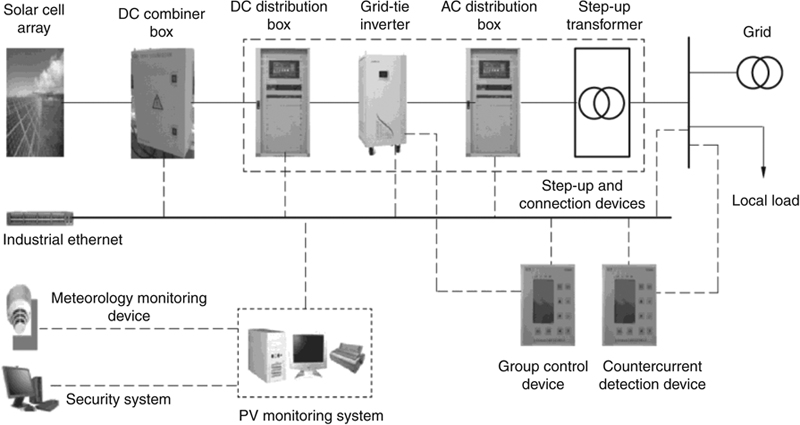
Figure 3.2 Structure of grid-connected PV power system.
3.3. Wind power
Wind energy is a clean renewable energy. Producing electricity is the major way to utilize wind energy, in which the kinetic energy of air in motion is converted to mechanical energy by the rotor and then the mechanical energy is converted to electricity by the generator. Wind power systems are also divided into independent type and grid-connected type.
3.3.1. Independent wind power system
An independent wind power system is not connected to a traditional electric power system and is mostly deployed in remote off-grid areas to meet local demand. To resolve intermittency of wind-produced electricity, such a system must be provided with ES. Figure 3.3 shows the structure of an independent wind power system, mainly including wind turbine generator, rectifier, controller, battery, off-grid inverter, and AC distribution box. The alternating current from the generator is first converted to direct current by the rectifier to charge the battery and then converted back to alternating current by the inverter to serve AC loads.

Figure 3.3 Structure of independent wind power system.
3.3.2. Grid-connected wind power system
A grid-connected wind power system is connected to a grid and injects electricity to it. It is the mainstream of wind power systems. Grid-connected wind power systems can be further divided into distributed type and centralized type. The former is a type of DG in a microgrid, in which electricity is directly distributed to users and the surplus or deficit is regulated by the grid. The latter is a wind power system that directly injects electricity to the grid for centralized distribution to users. The structures of the two types are essentially the same.
A grid-connected wind power system may be connected to the grid directly, via inverter or in a hybrid mode, depending on the wind turbine generator.
1. Direct connection: Asynchronous generators, including squirrel-cage asynchronous generator and wound induction generator, are directly connected to the grid. Figure 3.4 shows the schematic diagram of an asynchronous generator directly connected to the grid. The alternating current produced from the generator is directly injected to the grid.
2. Connection via inverter: Synchronous generators, including electrically excited synchronous generator and permanent-magnetic synchronous generator, are connected to the grid via an inverter. Figure 3.5 shows the schematic diagram of a synchronous generator connected to the grid via an inverter. The alternating current produced from the generator is first converted to direct current and then back to alternating current before it is delivered to the grid.
3. Connection in a hybrid mode: Doubly fed induction generators are connected to the grid in a hybrid mode, that is, the stator is directly connected to the grid while the rotor is of wound type and connected to the grid via inverter. Figure 3.6 shows the schematic diagram of a doubly fed induction generator connected to the grid in a hybrid mode.

Figure 3.4 Schematic diagram of an asynchronous generator directly connected to the grid.

Figure 3.5 Schematic diagram of synchronous generator connected to the grid via inverter.

Figure 3.6 Schematic diagram of doubly fed induction generator connected to the grid in a hybrid mode.
3.4. Microturbine
A micro gas turbine, or simply microturbine, is suitable for various traditional fuels. It makes low noise during operation, and has a much longer life and higher performance than a diesel generator. This small DG system has a short history and first appeared in the United States and Japan. It is advantageous because of its small size and weight, reduced maintenance, lower emissions, and high durability, making it popular in the world’s energy sector.
The microturbine is an emerging small heat engine, which works in a similar way to the trotting horse lamp popular in China’s Tang Dynasty. There is a rotor on the top of the lamp, and when the lamp is lighted, the air inside is heated and moves upward, thus driving the rotor and then the lamp to rotate. Similarly, in a microturbine, the fuel, such as natural gas, methane, petrol, and diesel, is combusted and becomes high-temperature and high-pressure gas, thus driving the rotor to rotate. The unit power ranges from 25 kW to 300 kW. A microturbine consists of a radial flow turbomachinery centripetal turbine and centrifugal compressor, with their rotors arranged back to back on the turbine rotor, an efficient plate regenerator, and a lubrication-free air bearing. The structure is much simpler, as the turbine and generator are integrated. A microturbine may be of a single-shaft or split-shaft structure.
Normally, a microturbine has a speed as high as 50,000–120,000 r/min. A single-shaft microturbine uses a permanent-magnet synchronous generator made of high-energy permanent magnetic materials (such as NdFeB), and the high-frequency alternating current produced is converted to power-frequency alternating current by a power electronic converter. A split-shaft microturbine is connected with the generator through variable-speed gear, and thus power-frequency alternating current can be generated by reducing the speed of the turbine. In a microturbine system, the high-temperature exhaust gas from the generator can be used to preheat the compressed air to be injected to the combustor, thus reducing fuel consumption for combustion and improving energy efficiency. With a lithium bromide absorption refrigerator or heat exchanger, the exhaust gas from the regenerator can be recycled to meet cooling and heat loads.
The components of a microturbine (taking a single-shaft microturbine as an example) are introduced in the subsequent section.
3.4.1. Components of microturbine
The high-speed microturbine is of a simple radial flow design, integrates the circulating reheat technology, and features high reliability, low maintenance cost, low-amplitude vibration, low emissions, and compact structure. It is mainly composed of a single-stage radial compressor, low-emission ring combustor, single-stage radial turbine, compression ratio, and air bearing or bearing with dual lubricating systems.
Figure 3.7 shows the three basic components of a microturbine, namely, the compressor, combustor, and turbine.
Compressor: Air flows through the inlet to enter the compressor, where its pressure and temperature are increased by the blades.
Combustor: The mixture of high-pressure air and natural gas sprayed to the combustor from around is ignited and heated and then expands rapidly.
Turbine: The heated, expanded gas enters the turbine and drives blades stage by stage and then the generator rotor to rotate.

Figure 3.7 Profile of a microturbine.
(1) Load coupling. (2) Axial/Radial inlet casing. (3) Radial bearing. (4) Rotor blade of compressor. (5) Mediate casing of compressor. (6) Rigid front support. (7) Disk. (8) Tie-rod. (9) Inlet casing. (10) Horizontal split surface. (11) Front plate of combustor. (12) Counter flow combustor. (13) Fuel distributor. (14) Flame tube of combustor. (15) Impingement cooling structure of combustor transition piece. (16) Stage-one nozzles. (17) Protective ring for stage-one stator blades. (18) Turbine rotor blade. (19) Exhaust diffuser. (20) Thermocouple of outlet casing.
(1) Load coupling. (2) Axial/Radial inlet casing. (3) Radial bearing. (4) Rotor blade of compressor. (5) Mediate casing of compressor. (6) Rigid front support. (7) Disk. (8) Tie-rod. (9) Inlet casing. (10) Horizontal split surface. (11) Front plate of combustor. (12) Counter flow combustor. (13) Fuel distributor. (14) Flame tube of combustor. (15) Impingement cooling structure of combustor transition piece. (16) Stage-one nozzles. (17) Protective ring for stage-one stator blades. (18) Turbine rotor blade. (19) Exhaust diffuser. (20) Thermocouple of outlet casing.
3.4.2. High-speed AC generator
The high-speed generator and microturbine are mounted on the same shaft. Thanks to its small size, the generator can be placed inside the microturbine to constitute a compact and high-speed turbine AC generator.
3.4.3. Regenerator
The regenerator increases the efficiency of the microturbine, making the microturbine more competitive than a reciprocating generator. It preheats the air to be injected to the combustor and thus reduces fuel consumption.
3.4.4. Converter system
The high-frequency alternating current produced from the generator must be converted to power-frequency alternating current by the power electronic converter under the control of a microprocessor. The power electronic converter can adjust the speed against load variation of the generator or the grid, or operate as an independent power source. The system facilitates remote management, control, and monitoring, as shown in Figure 3.8.
1. Soft start and rectifier unit: During startup of the system, the rectifier bridge operates as an inverter to enable soft start of the permanent-magnet synchronous motor (PMSM); during normal operation, the rectifier bridge functions as a rectifier.
2. Master inverter power unit: It mainly consists of an insulated gate bipolar transistor (IGBT) inverter bridge and power filter. It inverts and filters the input DC voltage of 720 V (±40 V) for integration to the grid.
3. Battery control and management unit: It controls and manages the smart charge, instantaneous loads, temperature compensation, discharge protection, activation, and self-test of batteries.
4. Power regulation unit: It outputs speed signals and adjusts the speed of the microturbine according to the optimal power-speed curve and the relationship between the output power and torque variation of the compressor.

Figure 3.8 Power converter system of a microturbine generator.
3.4.5. Control system
Figure 3.9 shows the structure of the microturbine control system, in which the regenerator is controlled by adjusting the opening of the active valve and bypass valve to control heat exchange between exhaust gas and clean air (i.e., regenerator effectiveness), so as to control the temperatures of the gas to enter the combustor from the compressor and the exhaust gas and thus improve energy efficiency.

Figure 3.9 Structure of microturbine control system.
The high-speed single-shaft microturbine is the mainstream type and the most commonly used for small CHP applications. When it is used in a microgrid, its operating status and control methods will affect its dynamic characteristics. Constant active power and reactive power control or U/f control may be adopted to ensure stability of the frequency and voltage of the microgrid when operating as an island.
Depending on the system structure, a microturbine may be connected to the grid through an inverter or directly.
1. Connection to grid through an inverter: A single-shaft microturbine generator rotates at a very high speed and produces a high-frequency alternating current, and hence, an inverter is required for connection to the grid. Figure 3.10 shows the schematic diagram of a single-shaft microturbine connected to the grid through an inverter. The high-frequency alternating current from the microturbine is first converted to direct current, and then to power-frequency alternating current before it is delivered to the grid.
2. Direct connection to grid: For a split-shaft microturbine, the power turbine and gas turbine are mounted on different shafts and connected with the generator through a speed-variable gear. As the generator speed is reduced, it can be directly connected to the grid. Figure 3.11 shows the schematic diagram of a split-shaft microturbine directly connected to the grid.

Figure 3.10 Schematic diagram of single-shaft microturbine connected to the grid through inverter.

Figure 3.11 Schematic diagram of split-shaft microturbine directly connected to the grid.
3.5. Other types of DGs
In addition to PV, wind, and microturbine discussed earlier, there are some other types of DGs that currently are not widely used due to immature technologies, including geothermal, biomass, and ocean energy. The following gives an outline of these energy forms.
3.5.1. Geothermal energy
Producing electricity is the major means to utilize geothermal energy. Similar to thermal power generation, in geothermal generation, the thermal energy of steam is converted to mechanical energy in the turbine to drive the generator to produce power. The difference is that geothermal generation does not require a huge boiler and uses geothermal sources instead of fuels. Geothermal power systems may be of flash steam type or binary cycle type, depending on the temperature of the geothermal source. Moreover, total flow generation and dry hot rock generation are currently under study.
3.5.2. Biomass energy
In the broad sense, biomass is the organic matter generated from the photosynthesis process of plants and therefore, its energy is converted from solar energy. Biomass energy may come from agricultural, forestry, and fisheries resources such as crops, wood, and seaweed, or industrial organic waste such as pulp waste, black liquid from paper making, and residue from alcoholic fermentation, or common municipal waste such as household garbage and paper scraps, or residual sludge from sewage treatment plants. Biomass power generation comes in three forms: (1) biomass combustion, (2) biomass gasification, and (3) methane combustion.
1. Biomass combustion: In biomass combustion electrification, the biomass is combusted in the boiler, the hot gas heats the heating surface of the boiler to produce high-temperature high-pressure steam, which expands in the gas turbine and drives the turbine to produce electricity. Generally, the biomass needs to be processed before combustion for a higher efficiency.
2. Biomass gasification: In biomass gasification electrification, the biomass is first converted to gas fuel by thermal chemical reaction, and then the gas fuel is purified and directly injected to the boiler, internal combustion engine, and combustor of the gas turbine to produce electricity.
3. Methane combustion: Methane combustion electrification emerges following the improved use of methane. The methane is used for the generator and other devices to produce power and heat.
3.5.3. Ocean energy
Ocean energy, a kind of renewable energy generated from the motion of seawater, mainly includes thermal gradient energy, tide energy, wave energy, tidal current energy, sea current energy, and salinity gradient energy. Accordingly, electrification technologies using ocean energy include tide electrification, sea current electrification, tidal current electrification, wave electrification, and thermal gradient electrification.
1. Tide electrification: Tide is a result of the relative motion of the Earth, Moon, and Sun, and thus is somewhat predictable. Tidal power is generated using the potential energy produced from the rise and fall of tides. Among all ocean energy technologies, it is the most mature and widely used type. The principle is as follows: a dam is built in an appropriate location. During the rise of tides, seawater flows to the dam reservoir and drives the hydraulic turbine to rotate to produce electricity; and during the fall of tides, the seawater flows back to the sea and also drives the turbine to produce electricity. As a result, the water turbine shall be able to rotate in the same direction irrespective of the direction of the water flow.
2. Sea current electrification: Sea current is an electrification form using the kinetic energy of sea currents and tidal currents moving in a given direction. The generation facility, similar to a wind turbine, is called “underwater windmill.” Facilities to convert the kinetic energy of sea currents to electricity may be of a propeller type, symmetrical airfoil and perpendicular shaft wheel type, and parachute type or magnetic flow type. The magnetic flow type works like this: when the sea currents containing large amounts of electric ions flow through the magnetic field, induced electromotive force will be generated and electricity is produced.
3. Tidal current electrification: Tidal currents are periodic seawater currents resulting from tides, and are similar to tides. They are weaker in the deep sea and stronger when getting closer to the shore, especially at the narrow entrance to a gulf or a narrow strait or waterway formed after separating from the land, where the water flows very fast. As such, the geographical distribution of fast-moving tidal currents is coincidental with that of large tidal ranges. To obtain energy from tidal currents, water turbine that can rotate in the same direction when the tidal currents flow in opposite directions is used. Different from tide electrification, tidal current electrification requires no dam or levee, and the tidal currents directly pass through the turbine by gravity to produce electricity.
4. Wave electrification: Wave electrification may be of floating type or stationary type. The principle is that waves move the water in the air chamber upward and downward and then the air above the installation moves back and forth, thereby driving the turbine to rotate and produce electricity.
5. Thermal gradient electrification: This is an electrification form using the temperature difference between surface water (at 26–27° C as most of solar radiation energy is converted to thermal energy) and deep water (at 1–6° C). It comes in two types, namely, closed circulating type and open circulating type. For the former type, the medium (ammonia or Freon) is evaporated by the heat of surface water (13–25° C) in the evaporator, enters the turbine, and drives the generator to rotate. Then the medium is cooled to liquid state by deep water in the condenser and is again sent to the evaporator by the circulating pump, in the same circulating sequence as in thermal power generation. For the latter type, the low-pressure surface water is sent to the evaporator with a vacuum pump, where a small portion of water is evaporated and the rest is sent back to the sea, and under the action of the vacuum pump, the evaporated water drives the turbine to produce electricity. After that, the water enters the condenser and is cooled and desalinated for drinking and industrial use.
3.6. Energy storage
ES technologies solve the imbalance between supply and demand. In distributed generation, they solve the intermittency and uncertainty of output and load shifting. They also enable a number of other functions such as black-start, power quality adjustment and control, and stability.
ES technologies include physical, electromagnetic, electrochemical, and phase-change forms. Physical ES technologies include pumped storage, compressed air ES (CAES) and flywheel ES; electromagnetic ES includes superconducting magnetic ES (SMES), supercapacitor, and high-energy-density capacitor; electrochemical ES includes various types of batteries such as lead-acid battery, nickel-hydrogen battery, nickel-cadmium battery, lithium-ion battery, sodium sulfur battery, and flow battery; phase-change form includes ice thermal storage.
3.6.1. Pumped storage
Pumped storage is a physical ES form. To use this form, an upstream reservoir and a downstream reservoir are required at the storage station. During off-peak hours, the pumped storage device operates as a motor to pump the water from the downstream reservoir to the upstream; and during peak hours, the device operates to produce electricity using the water in the upstream reservoir. A pumped storage station could have a capacity of energy for release for a few hours to a few days, with an efficiency ranging from 70% to 85%. Among all ES forms, this is the most widely used form in power systems, mainly for load shifting, frequency and phase modulation, emergency reserve, black-start, and system reserve. It can also improve the efficiency of thermal and nuclear power stations.
3.6.2. Compressed air ES
CAES is a physical ES form realized by means of gas turbine power generation and is intended for load shifting. It works like this: during off-peak hours, the excess power of the grid is used to compress the air, which is then stored in a typical 7.5 MPa sealed container and released during peak hours to drive the turbine to generate power. During the power generation, 2/3 of the gas is used to compress air, reducing gas consumption by 1/3, and the gas consumption is 40% less than that of a conventional gas turbine. CAES makes cold start and black-start possible, and can respond immediately. It is mainly for power regulation, load balance, frequency modulation, and distributed ES and reserve of power systems.
3.6.3. Flywheel ES
Flywheel is a physical ES form. A flywheel ES system is composed of a high-speed flywheel, bearing support system, motor/generator, power converter, electronic control system, and optional equipment including vacuum pump and backup bearing. During off-peak hours, the grid energizes the flywheel to rotate fast, thus realizing conversion from electricity to mechanical energy; during peak hours, the high-speed flywheel works as a prime mover for the generator to produce electricity and output current and voltage via the power converter, thus realizing conversion from mechanical energy to electricity. The flywheel is mainly used for uninterrupted power supply (UPS), emergency power system (EPS), load shifting, and frequency control.
3.6.4. Superconducting magnetic ES
SMES, an electromagnetic ES form, uses superconducting coils to store magnetic energy and requires no energy conversion for power transmission. It has such advantages as quick response (within several ms), high conversion efficiency, high specific capacity/power, and real-time large-capacity energy exchange with and power compensation for the electric power system. It is mainly used for voltage support, power compensation, and frequency regulation of TD networks to improve system stability and transmission capacity.
3.6.5. Supercapacitor
A supercapacitor, an electromagnetic ES form, is developed based on the electromagnetic double-layer theory and can provide very high pulse power. In the charging process, the charges on the surface of an ideally polarized electrode will attract the ions of opposite polarity in the electrolyte to the electrode surface, forming an electric double-layer and thus an electric double-layer capacitor. As the spacing between the two layers is very small, generally less than 0.5 mm, and the electrode is of a special structure, the surface area of the electrode increases by tens of thousands of times, creating an extremely large capacitance. However, due to the low voltage withstand level of the dielectric medium and occurrence of current leakage, the amount and duration of energy storage are limited, and supercapacitors must be series-connected to increase the volume of the charge and discharge control circuit and the system. The supercapacitor is mainly used for short-time and high-power load shifting, for reliable supply following a voltage drop and instantaneous disturbance, and in situations of high peak power, for example, support for startup and dynamic voltage recovery of a high-power DC motor.
3.6.6. Battery
Battery is a chemical ES form and comes in many types, mainly lead-acid battery, nickel-cadmium battery, lithium-ion battery, sodium sulfur battery, and vanadium redox flow battery.
1. Lead-acid battery: Its lifetime will be reduced when working at a high temperature. Similar to a nickel-cadmium battery, it has a low specific energy and specific power, but is advantageous because of its low price and cost, high reliability, and mature technology and has been widely used in electric power systems. However, it has a short lifetime and causes environmental pollution during manufacture. It is mainly used as the power source for closing of circuit breakers during system operation, and an independent power source for relay protection, driver motor, communication, and emergency lighting in the event of failure of power plants or substations.
2. Nickel-cadmium battery: It has a high efficiency and long lifetime, but the capacity decreases as time goes by, and the charge retention needs to be enhanced. Furthermore, it has been restricted by the EU due to heavy metal pollution. It is rarely used in electric power systems.
3. Lithium-ion battery: It has a high specific energy and specific power, little self-discharge, and causes no pollution. However, due to the influence of the process and difference in ambient temperature, the system indices are more often worse than those of a cell, and in particular, the lifetime is several times or even more than 10 times shorter than that of a cell. What is more, integration of a high capacity is very difficult and the cost for manufacture and maintenance very high. In spite of this, the lithium-ion battery is expected to be widely used in DG and the microgrid thanks to advancements of technologies and reduction of costs.
4. Sodium sulfur battery: Owing to its high energy density, its size is just 1/5 of a lead-acid battery while the efficiency is up to 80%, contributing to convenient modular design, transportation, and installation. It can be installed by stage according to the intended purpose and capacity, and suits urban substations and special loads. It is a promising ES technology for DG and the microgrid in improving the system stability, shifting loads, and maintaining power supply in an emergency.
5. Flow battery: Flow battery features slight electrochemical polarization, 100% discharge, long lifetime, and rated power independent of rated capacity. The capacity can be increased by adding electrolyte or increasing the concentration of the electrolyte. The storage form and pattern can be designed according to the location. It is a promising ES technology for DG and the microgrid in improving the system stability, shifting loads, and maintaining power supply in an emergency.
..................Content has been hidden....................
You can't read the all page of ebook, please click here login for view all page.