
Chapter 11
A practical case
Abstract
A practical case, introduces engineering design and test schemes by taking a specific project as example.
Keywords
practical case
microgrid system combining PV and ES
trial project
11.1. Project background
In 2010, the State Grid Corporation of China (SGCC) launched the plan for the second batch of pilot programs in its [2010] No. 131 document, and Henan Electric Power Company, as SGCC’s only trial distributed generation (DG) connection point, undertook the demonstration program “Comprehensive study on operation control of microgrid containing PV and ES and engineering application” with the 380 kW photovoltaics (PV) power system in the new campus of Henan College of Finance and Taxation.
PV power is of low stability and dispatchability, and may cause difficulty in harmonics management for the grid. To address such problems, the microgrid is set up to allow for distributed generation. Integrating PV power to a distribution network on a local balance basis can facilitate interaction and management of the power grid and loads, and promote utilization of DG, development of smart households, and construction of smart grid and interaction service system. Thus, it is necessary to implement trial projects and conduct studies on the possible maximum integration of DGs to reduce energy consumption and improve energy efficiency, power reliability, disaster prevention capability, and postdisaster emergency supply capability of the entire grid.
11.2. Project description
The new campus of Henan College of Finance and Taxation is situated in the planned Henan occupational education cluster, 3 km east of the intersection of Beijing–Zhuhai Expressway and Zhengkai Road, Baisha Town, Zhongmu County, Zhengzhou. It has a total floor area of 556,000 m2 and a planned building area of 342,713 m2, and over 43,500 m2 of rooftop areas can be used for PV generation, accommodating a total installed capacity of 2 MW. In view of the design of the seven dormitories, a 380 kW microgrid system combining PV and ES is deployed.
Specifically, the 380 kW PV system is a building-integrated-PV (BIPV) demonstration project jointly launched by the Ministry of Finance and the Ministry of Housing and Urban–Rural Development of China, which will be constructed by Henan College of Finance and Taxation in accordance with given technical requirements; the energy storage (ES) system has a capacity of 2 × l00 kW/100 kWh and uses lithium iron phosphate batteries; the microgrid, including three PV circuits, two ES circuits, and 32 low-voltage (LV) distribution circuits, covers the dormitories and canteens in the No. 4 distribution area of the campus and communicates with the dispatch center of Zhongmu Electric Power Company.
Figure 11.1 shows the primary connection of the microgrid system, where the section circled with a dotted line is the coverage area of the microgrid. In the system, the PV system is connected to the grid on the LV side of the No. 4 distribution area at 380 kV. The DC outputs of PV cells on the rooftop of the seven students’ dormitories are first collected and then respectively connected to the two busbar sections on the LV sides of the two distribution transformers in the No. 4 distribution area via inverters. The two sets of 100 kW/100 kWh lithium iron phosphate batteries are respectively connected to the two busbar sections on the LV sides of the two distribution transformers in the No. 4 distribution area via a power converter system (PCS).
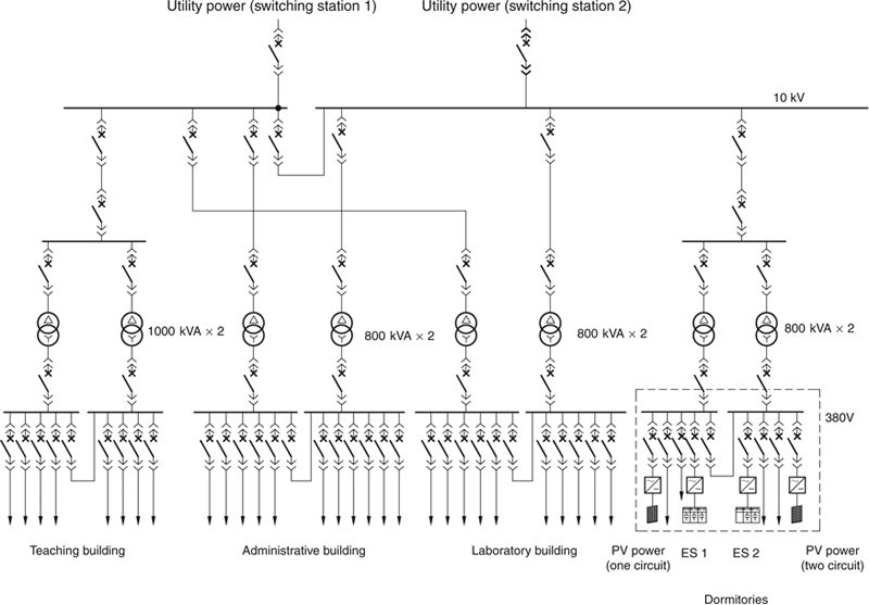
Figure 11.1 Schematic diagram of primary connection of the PV–ES combined microgrid system.
The loads of the system vary seasonally. When the school is open, the power loads may peak at around 600 kW, and the PV power can all be consumed locally; while during the holidays, the loads will fall below 50 kW, when PV generation exceeds power demand, and surplus power will flow to the distribution network.
11.3. System design
11.3.1. Three-layer control system
The control system is of a three-layer architecture, namely, distribution network dispatch layer, centralized control layer, and local control layer, as shown in Figure 11.2. The distribution network dispatch layer, the upper layer, coordinates and dispatches the microgrid to maintain security and economy of the distribution network, and the microgrid is regulated and controlled by the distribution network. The centralized control layer, the middle layer that manages the DRs and various loads in a centralized way, can maintain the microgrid in optimal operation in grid-connected mode and maintain the stability and security of the microgrid in islanded mode by regulating the output of DRs and consumption of various loads. The local control layer, the lower layer, controls various DGs and loads to maintain transient security of the microgrid.

Figure 11.2 Three-layer control system of the microgrid.
11.3.2. System design
11.3.2.1. PV system
The PV system is connected to the microgrid in three circuits through four inverters, including three 100 kW inverters and one 50 kW inverter. Specifically, two 100 kW inverters are separately connected to the grid, and the other 100 kW inverter and the 50 kW inverter are connected to the grid as one circuit. In addition to their own operation parameters, the inverters are also capable of adjusting their output. The inverters are all installed in the No. 4 distribution area.
The PV power is connected to the grid via an inverter and LV cabinet. The LV cabinet is equipped with electrically operated LV circuit breaker and meters (including power quality meter) to measure the common operation parameters (including voltage, current, active power, and reactive power) and power quality (voltage harmonics and current harmonics of 2nd to 31st orders) of the PV circuits.
11.3.2.2. ES circuits
The two batteries are respectively connected to the two busbar sections via two 100 kW PCSs. In addition to its own operation parameters, the PCS is also capable of output regulation and mode transfer. When the microgrid is out of service, the “black start” function can restore the microgrid back to normal operation quickly.
11.3.2.3. Load circuits
Load circuits are connected to the microgrid through the LV cabinet, which is equipped with an electrically operated LV circuit breaker. Common meters are installed to measure the common operation parameters of the load circuits including voltage, current, active power, and reactive power.
11.3.2.4. PCC circuit
The point of common coupling (PCC) circuit is connected with MSD-831, a grid connection and separation controller that collects the voltage and current of various PCC branches. It can rapidly control the circuit breaker at the PCC, and enables islanding detection, tripping following line faults, synchronous grid-connection after recovery from fault, and autoswitching of standby busbar (see Figure 11.3).

Figure 11.3 Schematic diagram of the PCC circuit.
11.3.2.5. LV busbar circuit
The LV busbar circuit is connected with MSD-832, a centralized load controller that collects busbar voltage. At the instant of islanding, it can establish balance between generation and consumption within the microgrid and execute emergency control to remove unimportant loads (or trip some DGs, as the case may be), and during islanded operation, can shed loads at low frequency and low voltage and trip generators at high frequency and voltage to maintain the frequency and voltage of the microgrid within the allowable range (see Figure 11.4).

Figure 11.4 Schematic diagram of microgrid load controller.
11.3.2.6. Microgrid central controller
The microgrid control center (MGCC) is equipped with MCC-801 as the centralized controller. Through IEC 61850 communication protocol, it can realize data access, monitoring, and energy management of the entire microgrid. It plays the most important role in microgrid control. As shown in Figure 11.5, MCC-801 communicates with the PV inverter, PCS, grid connection and separation controller, and load controller through Ethernet.

Figure 11.5 Structure of the control system.
11.3.2.7. Monitoring system
The monitoring system monitors the operation of the entire microgrid by collecting the analog values and Boolean values of the LV measurement and control unit, DG inverter, and grid connection and separation controller in real time.
11.3.3. Energy management system
The energy management system makes statistics and advanced analysis of the microgrid in real time on the basis of supervisory control and data acquisition (SCADA). In particular, advanced analysis includes automatic transfer between grid-connected mode and islanded mode, energy dispatch in islanded mode (to automatically maintain balance between generation and consumption), ES charge and discharge curve control, and power exchange control in an emergency (coordinated with the distribution network).
11.3.3.1. Power exchange control in emergency
In special situations (e.g., an earthquake, snowstorm, or flood), the microgrid can serve as reserve to the distribution network, thereby providing effective support to the macrogrid and speeding up recovery of the macrogrid from failure. In this case, the distribution system will specify the amount of power exchange and inform the microgrid, and the MGCC will coordinate the DGs, ESs, and loads according to the specified amount of power exchange.
11.3.3.2. ES charge and discharge curve control
The energy management system defines the expected charge and discharge curves of ESs according to power consumption and PV generation in peak hours and off-peak hours in grid-connected mode, and controls the state of charge (SOC) and charge power and discharge power of ESs in real time according to the curves, thus allowing for load shifting and balance of power consumption and generation.
11.3.3.3. Grid connection and separation control
Upon receiving grid connection orders from the grid connection and separation controller, the energy management system informs the ESs to switch to islanded mode; while upon receiving grid separation orders from the grid connection and separation controller, the energy management system informs the ESs to switch to grid-connected mode.
11.3.3.4. Power balance control in islanded mode
In islanded operation, the energy management system monitors the power generation and consumption of the entire microgrid in real time, restores power supply to loads previously shed, and adjusts the outputs of the PV system and ESs, thus ensuring high reliability and quality of power supply to the most important loads, and keeping the outputs of various DGs and ESs within the allowable range.
To maintain power balance within the microgrid, load shedding or adjustment of DG outputs are required. In load shedding, unimportant loads come before important loads. In adjusting DG outputs, the maximum outputs of renewable energy should be maintained as practical as possible, and then the energy is charged to or discharged from the ESs.
11.3.3.5. Automatic recovery after transfer from islanding to grid connection
When it is detected that the microgrid has been reconnected to the grid, the DGs and loads that were previously removed are reconnected, the DG outputs are adjusted to the maximum, and the ESs are charged, thus restoring the microgrid to normal grid-connected operation and making it ready for possible islanding.
11.3.4. Dispatch of distribution network
Telecontrol equipment is provided at the centralized control layer, which sends the operation information at the PCC to the dispatch automation system of the distribution network. According to economic analysis of the distribution network, the dispatch automation system delivers power exchange regulation orders to the microgrid, making the microgrid a controllable unit of the distribution network.
When the microgrid is in grid-connected operation, the distribution network dispatch layer sends dispatch orders to the microgrid to keep it operating with a specified amount of power exchange, and cooperates with the distribution network in load shifting, economic and optimal dispatch, and rapid recovery from failure.
11.4. Operation of microgrid
11.4.1. Operation of the integrated monitoring system
The integrated monitoring system monitors the system voltage and frequency of the microgrid, voltage at the PCC, power of the distribution network, total outputs of DGs, SOC of ESs, and loads within the microgrid. Figure 11.6 shows the operation screens of the integrated monitoring system, Figure 11.7 shows the daily busbar voltage curve of the microgrid, and Figure 11.8 shows the daily system frequency curve of the microgrid.

Figure 11.6 Operation screens of the integrated monitoring system.
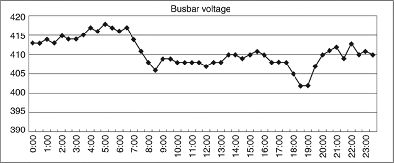
Figure 11.7 Daily busbar voltage curve of the microgrid.
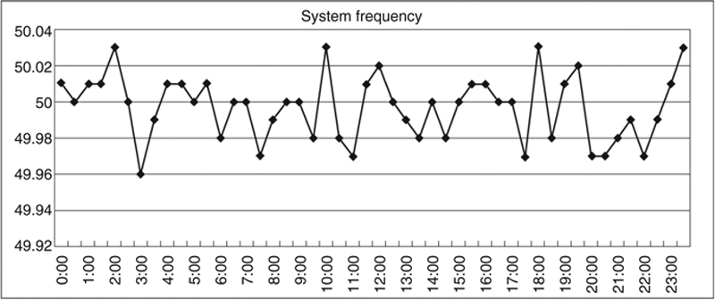
Figure 11.8 Daily system frequency curve of the microgrid.
11.4.2. Operation of the PV system
There are four PV inverters in total, among which the output power of the three 100 kW inverters can be adjusted from 10% to 100%, while that of the 50 kW inverter cannot be adjusted. The startup time of the inverters can be adjusted. To avoid impacts on the PCS due to simultaneous startup of the four inverters in islanded operation, the four inverters are started at different times.
In grid-connected mode, the PV inverters operate at the maximum output; in islanded mode, they operate at the output as specified by the MGCC. Figure 11.9 shows the monitoring screen of operation of the PV system, Figure 11.10 shows the daily output curve of the 100 kW PV inverter, Figure 11.11 shows the voltage waveform of the 380 V busbar in grid-connected mode, and Figure 11.12 shows the voltage spectrum of the 380 V busbar in grid-connected mode, where voltage harmonics are mainly odd harmonics of third, fifth, seventh, and ninth orders, and the total harmonic distortion and contents of various orders of harmonics all meet the requirements of applicable national standards.
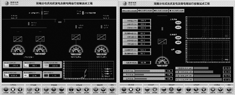
Figure 11.9 Monitoring screen of operation of the PV system.

Figure 11.10 Daily output curve of 100 kW PV inverter.

Figure 11.11 Voltage waveform of the 380 V busbar in grid-connected mode.
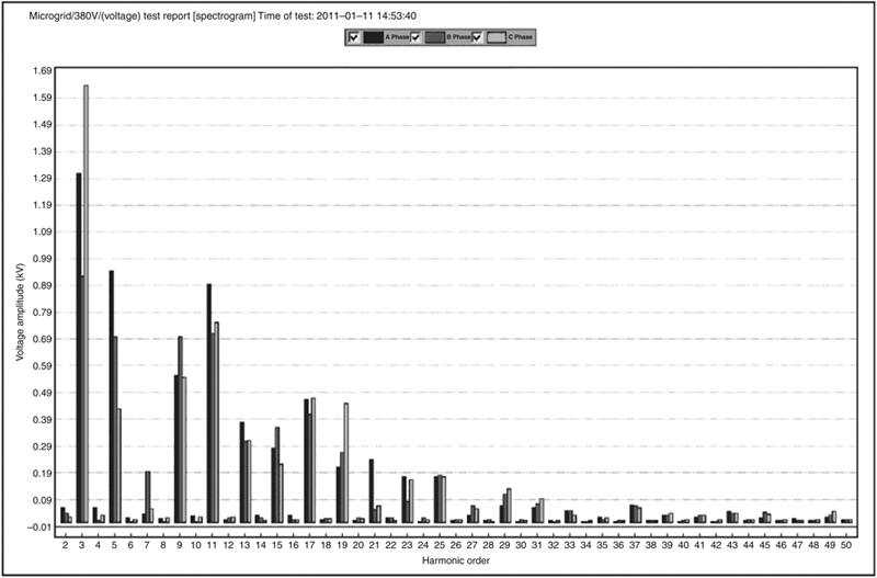
Figure 11.12 Voltage spectrum of the 380 V busbar in grid-connected mode.
11.4.3. Monitoring of ES
In grid-connected operation, the PCS operates in P/Q control and regulates its output as specified by MGCC. In islanded operation, the PCS operates in U/f control, outputs power at a constant frequency and voltage, and acts as the master power source for the microgrid. Figure 11.13 shows the operation monitoring screen of ES.

Figure 11.13 Operation monitoring screen of ES.
11.5. Tests
11.5.1. Test on transfer from grid-connected mode to islanded mode
Purpose: To verify that the microgrid can automatically switch to islanded operation and maintain stability in the mode following an outage in the macrogrid.
Method: Open the switch on the 10 kV side of the distribution transformer to simulate macrogrid outage.
Process: The grid connection and separation controller detects outage of the macrogrid and opens the circuit breaker at the PCC, thus entering the islanded mode. The grid connection and separation controller also sends grid separation signals to the PCS and microgrid control system, and the load control device sheds unimportant loads. After receiving the grid separation signals, the PCS switches to the islanded mode and outputs power at a constant frequency and voltage, and the microgrid control system immediately executes control on the transfer from grid-connected mode to islanded mode.
Figure 11.14 shows the voltage waveform of the 380 V busbar during transfer from grid-connected mode to islanded mode, Figure 11.15 shows the current waveform of the PCS during transfer from grid-connected mode to islanded mode, Figure 11.16 shows the current waveform of the PV inverter during transfer from grid-connected mode to islanded mode, and Figure 11.17 shows the voltage trend during transfer from grid-connected mode to islanded mode and then to grid-connected mode. During the transfer from grid-connected mode to islanded mode, due to loss of support from the macrogrid, the circuit breakers of the main incoming line and unimportant loads open quickly, and instantly the microgrid loses power, the PV system quits service, and the ESs switch from grid-connected mode to islanded mode. Five to 10 seconds later, the microgrid enters the islanded mode, and the busbar voltage and system frequency restore to normal level. As such, after separating from the macrogrid, the microgrid experiences a short-time outage before entering the islanded mode.

Figure 11.14 Voltage waveform of the 380 V busbar during transfer from grid-connected mode to islanded mode.

Figure 11.15 Current waveform of the PCS during transfer from grid-connected mode to islanded mode.

Figure 11.16 Current waveform of the PV inverter during transfer from grid-connected mode to islanded mode.

Figure 11.17 Voltage trend during the transfer from grid-connected mode to islanded mode and then to grid-connected mode.
11.5.2. Islanded operation test
Purpose: To verify that the microgrid can maintain stability, and achieve optimal output of the PV system and reasonable utilization of ESs by regulating PV power output in islanded mode.
Method: Open the switch on the 10 kV side of the distribution transformer to simulate macrogrid outage, and then the microgrid switches to islanded mode.
Process: In islanded mode, the ESs output power at a constant frequency and voltage to maintain the voltage and frequency of the LV busbar at 380 V and 50 Hz, respectively. The centralized control device of the microgrid regulates output of the PV system, output of auxiliary ESs, and connection and disconnection of loads, to maintain maximum PV output and continuous power supply to important loads, prevent overcharge and overdischarge of batteries, and ensure power supply to less important loads as much as possible. Figure 11.18 shows the voltage waveform of the 380 V busbar in islanded mode, and Figure 11.19 shows the voltage spectrum of the 380 V busbar in islanded mode.

Figure 11.18 Voltage waveform of the 380 V busbar in islanded mode.

Figure 11.19 Voltage spectrum of the 380 V busbar in islanded mode.
11.5.3. Test on transfer from islanded mode to grid-connected mode
Purpose: To verify that the microgrid can automatically switch to grid-connected mode from islanded mode after the macrogrid has recovered from power failure.
Method: Close the switch on the 10 kV side of the distribution transformer to resume power supply by the macrogrid.
Process: When the grid connection and separation controller detects that the voltage on the distribution network side is in the step with the busbar voltage on the LV side in islanded operation, it sends a mode transfer order to the PCS and the PCS switches to P/Q control from U/f control, closes the circuit breaker at the PCC, and the control system executes control over the transfer from islanded mode to grid-connected mode. Figure 11.20 shows the voltage waveform on the 380 V busbar during the transfer from islanded mode to grid-connected mode, Figure 11.21 shows the current waveform of the PCS during transfer from islanded mode to grid-connected mode, and Figure 11.22 shows the current waveform of the PV inverter during the transfer from islanded mode to grid-connected mode. When the microgrid transfers from islanded mode to grid-connected mode, the voltage of the 380 V busbar drops and instantly resumes normal level, the PV inverter realizes low-voltage ridethrough, thus ensuring uninterrupted PV generation, and the ESs also resume normal operation, thus realizing smooth transfer from islanded mode to grid-connected mode. The voltage trend during the transfer from islanded mode to grid-connected mode is shown in Figure 11.17.

Figure 11.20 Voltage waveform of the 380 V busbar during transfer from islanded mode to grid-connected mode.

Figure 11.21 Current waveform of the PCS during transfer from islanded mode to grid-connected mode.

Figure 11.22 Current waveform of the PV inverter during transfer from islanded mode to grid-connected mode.
11.5.4. Grid-connection recovery test
Purpose: To verify that the microgrid can operate normally after being reconnected to the grid.
Process: When the microgrid is reconnected to the grid, the centralized control device of the microgrid reconnects unimportant loads previously shed in islanded mode, regulates the output of the PV inverter to the maximum, and automatically charges the ES to prepare for possible islanding.
11.5.5. ES charge and discharge control
Purpose: To verify that the ESs can be charged or discharged as required. Specifically, in peak hours, the ES can automatically discharge energy and in off-peak hours, the ES can automatically charge, thus realizing load shifting for the grid and improving the operation environment of the grid.
Process: Set the charge power and discharge power of the ESs according to peak hours and off-peak hours of the system to establish the charge and discharge power curve, and the control system automatically controls the output of the ES in real time according to the curve.
11.5.6. Power exchange control
Purpose: To test the response of the microgrid system to power exchange dispatch orders from the upper level.
Method: Manually set the value of power exchange to simulate dispatch orders delivered from the upper level.
Process: Set the target output power, and the system automatically regulates the PV output and ES, or even temporarily sheds unimportant loads (in emergency cases), to keep the actual power exchange as close as possible to the specified value, and the microgrid can provide support for the distribution network.
..................Content has been hidden....................
You can't read the all page of ebook, please click here login for view all page.