
Chapter 9
Harmonic control of the microgrid
Abstract
Harmonic control of the microgrid, introduces harmonic control technologies.
Keywords
harmonics control
passive filter
single-tuned filter
high-pass filter
double-tuned filter
harmonics compensation
active power filter (APF)
The harmonics in microgrid come from two sources: background harmonics produced from the power system connected with the microgrid, and harmonics produced by the nonlinear loads and equipment (including inverters) of the microgrid. Effective harmonic control can improve power quality and ensure normal operation of loads.
In a microgrid, most distributed generation (DG) or power systems are connected to the grid through power electronic converters, such as grid tie inverter and power converter system (PCS) for photovoltaic (PV) power, and wind power. These devices are harmonic sources. With the advance of technologies, these devices will have more functions. It has become a trend for grid tie inverters to work also for power quality control.
9.1. Harmonic control technologies
9.1.1. Passive filtering of grid tie inverter
A passive circuit can be used to remove harmonics generated by the grid tie inverter, mostly harmonics at around the switching frequency of the inverter, or high-order harmonics of an integer multiple of the switching frequency. Let the switching frequency of the inverter be fk, then the frequency of the harmonics generated by the inverter is nfk + l. Figure 9.1 shows the topology of the passive filtering circuit, which can only remove the high-order harmonics generated by the inverter, but not those generated by loads.

Figure 9.1 Passive filtering circuit of grid tie inverter.
9.1.2. Active filtering of grid tie inverter
With proper control means, a grid tie inverter can also act as an active power filter. This requires the sinusoidal pulse width modulation (SPWM) technology to generate a desired harmonic current to be superimposed on the sinusoidal voltage generated on the AC side of the inverter, provided that the said harmonic current is equal to but in opposite phase with the harmonic current generated by loads of the grid. Such an inverter is called an active filtering grid tie inverter.
9.1.3. Separately configured filtering technologies
If the grid tie inverter is properly controlled such that the iron-core reactor series-connected with the inverter is free from magnetic saturation, harmonics injected to the grid from the inverter can be ignored. However, since the loads also generate harmonics, the grid still suffers excessive harmonics under some circumstances. As such, the control system of the microgrid should also be equipped with active or passive power filters sometimes.
A low-voltage (LV) LC single-tuned filter can be used as the passive filtering circuit for a microgrid. The single-tuned filter is designed with a certain margin considering the effects of quality factor during resonance. Given the relatively high fundamental current in an LV system, the passive high-pass filter is not recommended.
An active power filter composed of power electronic devices may be used as the active filtering circuit for microgrid. As the harmonic current occurring in the microgrid is relatively low, an active power filter with a limited capacity can provide sufficient harmonic control.
9.2. Passive filtering technologies
9.2.1. Basic principles of passive filter
A passive filter is an appropriate combination of filter capacitor, reactor, and resistor (or using the resistance provided by the reactor). By connecting it in parallel with the harmonic source, it can both filter harmonics and provide reactive power compensation. It is also known as LC filter as it is composed of inductors (represented by the letter L) and capacitors (represented by the letter C). LC filters can be further divided into single-tuned filter, double-tuned filter, and high-pass filter, with the first and third types often used.
9.2.1.1. Single-tuned filter
Figure 9.2a shows the circuit diagram of a single-tuned filter. The impedance of the filter with respect to nth harmonic ωn = nωs is
 (9.1)
(9.1)where fn refers to the single-tuned filter for nth harmonics.

Figure 9.2 Circuit diagram and impedance-frequency characteristic of single-tuned filter.
(a) Circuit diagram and (b) impedance-frequency characteristic.
(a) Circuit diagram and (b) impedance-frequency characteristic.
The impedance-frequency curve of the filter is shown in Figure 9.2b.
A single-tuned filter works based on the LC resonant circuit, and the harmonic order n at the point of resonance is given by:
 (9.2)
(9.2)At the point of resonance, Zfn = Rfn. Since Rfn is very small, most of the nth harmonic current flows to the filter while only a small portion flows to the grid. While for harmonics of other orders, Zfn ≠ Rfn, and only a minor portion of current flows to the filter. Simply put, as long as the harmonic order at the point of resonance is set to the order of harmonics to be removed, most of harmonic current of this order will flow to the filter and thus effectively be removed.
9.2.1.2. High-pass filter
High-pass filter, also known as damped filter, comes in four types, respectively first-order type, second-order type, third-order type, and C-type, as shown in Figure 9.3.

Figure 9.3 Circuit diagrams of high-pass filter.
(a) First-order, (b) second-order, (c) third-order, and (d) C-type.
(a) First-order, (b) second-order, (c) third-order, and (d) C-type.
The first-order high-pass filter requires a capacitor with a very high capacity and thus causes very high fundamental losses, and therefore, is seldom used.
The second-order high-pass filter has the best performance, but causes higher fundamental losses compared with the third-order type.
The third-order high-pass filter has an additional capacitor C2 compared with the second-order type. It has a capacity much lower than that of C1, thus increasing the impedance of the filter to the fundamental frequency, and significantly reducing fundamental losses. This is a major advantage of the third-order high-pass filter.
The performance of C-type high-pass filter falls between the third-order type and the second-order type. C2 and L are tuned at the fundamental frequency, thus significantly reducing fundamental losses. But the disadvantage is that it is sensitive to detuning of fundamental frequency and parameter drift of devices.
Among the above four types of high-pass filters, the most commonly used is second-order type at present. Its impedance is given by:
 (9.3)
(9.3)9.2.1.3. Double-tuned filter
In addition to single-tuned filter and high-pass filter, double-tuned filters are also used. Figure 9.4 shows the circuit diagram of a double-tuned filter. It is equivalent to two parallel-connected single-tuned filters as it has two resonance frequencies and absorbs harmonics at these two frequencies. Compared with two single-tuned filters, a double-tuned filter causes lower fundamental losses and uses only one inductor (L1) to withstand all the surge voltage. In normal operation, the fundamental-frequency impedance in the series circuit is much higher than that in the parallel circuit; therefore, the power-frequency voltage occurring in the latter circuit is much lower than that in the former circuit. Moreover, only the reactive component of the harmonic current flows through the parallel circuit as the capacity of C2 is generally pretty small. On the other hand, the double-tuned filter has a rather complicated structure and is difficult to tune. Due to the low cost, double-tuned filters have been applied in some HVDC projects worldwide in recent years.

Figure 9.4 Circuit diagram of double-tuned filter.
9.2.2. Design of passive filter
1. Measurement and analysis of harmonic sources: Prior measurement and analysis of the power system and its loads is required to determine the harmonic voltage and current of various orders injected to the system from the harmonic sources, the harmonic distortion rate, the harmonic impedance and reference capacity of the system, and measure the positive and negative frequency offsets and background harmonics of the system (the effects of background harmonics may be considered as 110% of various orders of harmonics generated by the harmonic sources); analyze the composition and operation modes of loads; and identify the causes for harmonics, the operating time and changes of loads generating harmonics, and reactive power compensation.
2. Determination of filter design: Filter design involves determination of filter type and the corresponding harmonic order. Single-tuned filters are mainly used to remove high-content characteristic harmonics while high-pass filters remove higher-order harmonics excluding characteristic harmonics.
3. Calculation of parameters of single-tuned filter: The parameters include the impedance, withstand voltage, and capacity of the reactor and capacitor comprising the filter.
9.3. Active filtering technologies
Figure 9.5 shows the circuit of a three-phase active power filter, where LR is the filter reactor, which also serves to convert the voltage to current, CR is a high-frequency filter capacitor, VT1, VT2, VT3, VT4, VT5, and VT6 are IGBT components, VD1, VD2, VD3, VD4, VD5, and VD6 are fast recovery diodes, and C is an electrolytic capacitor. The filter is generally parallel connected with nonlinear loads and injects to the grid a harmonic current equal to but in opposite phase with the harmonic current generated by the nonlinear loads, thus making the total harmonic current approach zero and effectively eliminating the effects of harmonics.

Figure 9.5 Circuit diagram of three-phase active power filter.
The active power filter for a microgrid is a voltage source inverter composed of power electronic devices. It operates as a controlled current source and its output current, having the same frequency and phase as the system voltage, flows to the system through the connecting reactor. By detecting the harmonic current induced by loads in real time, the filter is controlled to inject to the power system a current with the same waveform and opposite direction as the load induced harmonic current, for the purpose of harmonic compensation. An active power filter mainly has the following functions:
1. Dynamically suppress the harmonic current flowing to the grid, to reduce the THD content of the current;
2. Improve the power quality of the distribution network;
3. Compensate reactive power for loads, to increase the power factor and save energy;
4. Prevent occurrence of LC resonance in the grid, improve security of the distribution network, and protect reactive compensation devices;
5. Reduce feeder losses and improve the efficiency of the distribution network.
An active power filter is mainly composed of incoming line contactor, filter, IGBT inverter, and control and protection, as shown in Figure 9.6. The control system of the active power filter detects the current on the load side and the system voltage at the connection point in real time, calculates the current required for harmonic compensation, and controls the three-phase IGBT inverters to give current tracking and compensation orders to suppress harmonics on the load side. Besides, the filter is also capable of protection against AC overvoltage/undervoltage, output overcurrent, DC overvoltage/undervoltage, short circuit of inverter, and overheating of inverter.
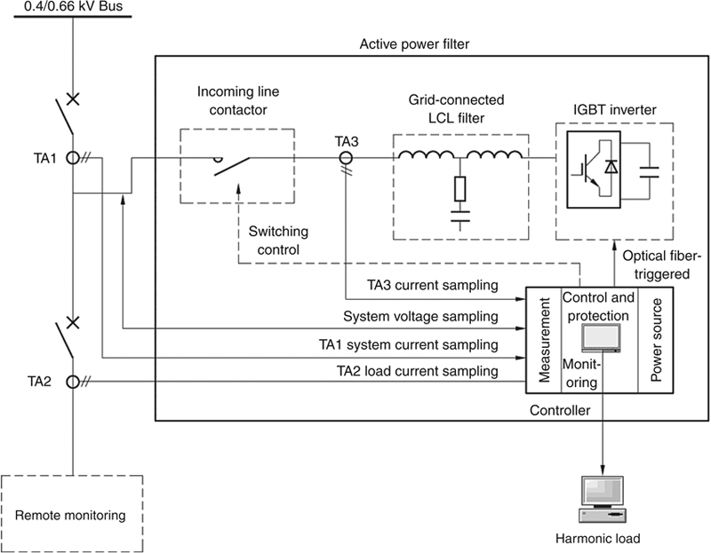
Figure 9.6 Block diagram of system configuration.
..................Content has been hidden....................
You can't read the all page of ebook, please click here login for view all page.