Chapter 9: Specialized Processor Extensions
In the preceding chapters, we discussed the features of general-purpose computer architectures as well as some architectural specializations intended to address domain-specific requirements. This chapter will focus on extensions commonly implemented at the processor instruction set level to provide additional system capabilities beyond generic computing needs.
After reading this chapter, you will understand the purpose of privileged processor modes and how they operate in multiprocessing and multiuser contexts. You will be familiar with the concepts of floating-point processors and instruction sets, techniques for power management in battery-powered devices, and processor features intended to enhance system security.
We will discuss the following processor extensions in this chapter:
- Privileged processor modes
- Floating-point mathematics
- Power management
- System security management
Technical requirements
The files for this chapter, including solutions to the exercises, are available at https://github.com/PacktPublishing/Modern-Computer-Architecture-and-Organization.
Privileged processor modes
Most operating systems running on 32-bit and 64-bit processors control access to system resources using the concept of privilege levels. The primary reasons for managing access in this manner are to enhance system stability, prevent unauthorized access to system hardware, and prevent unauthorized access to data.
Privileged execution improves system stability by ensuring only trusted code is allowed to execute instructions with unrestricted access to resources such as processor configuration registers and I/O devices. The operating system kernel and related modules, including device drivers, require privileged access to perform their functions. Because any crash of a kernel process or a device driver is likely to halt the entire system immediately, these software components generally undergo a careful design process and rigorous testing before being released for general use.
Running the operating system in a privileged context prevents unauthorized applications from accessing system-managed data structures such as page tables and interrupt vector tables. Whether by accident or as a result of malicious intent, a user application may attempt to access data contained in system-owned memory or in memory belonging to a different user. The system prevents such access attempts from succeeding, and informs the misbehaving application of its transgression by initiating an exception, which commonly results in a program crash with an error message.
Chapter 3, Processor Elements, introduced the concepts associated with interrupts and how they are handled by the processor. Before getting into the details of privileged processor modes, we will first discuss interrupt and exception handling in more detail.
Handling interrupts and exceptions
Hardware interrupts, as we have seen, allow processors to respond promptly to requests for services from peripheral devices. A hardware interrupt notifies the processor of a need to take some action, usually involving data transfer to or from an external device.
Exceptions are similar to interrupts, with the key difference that exceptions generally involve responding to some condition arising internal to the processor. One example of an internally generated exception is division by zero.
It is possible for user code to intentionally generate exceptions. In fact, this is a standard method used by unprivileged code to request system services provided by privileged code in the operating system kernel and device drivers.
The distinction between the terms interrupt and exception is not precisely defined. Interrupt processing and exception processing typically rely on the same or similar processor hardware resources operating in much the same manner. In fact, in the x86 architecture, the mnemonic for the instruction that initiates a software interrupt (or exception) is int, short for interrupt.
Exceptions include error conditions occurring during software execution such as division by zero, as well as non-error situations such as page faults. Unless the interrupt or exception results in the drastic response of terminating the application, an interrupt service routine or exception handler processes the event and returns control to the system scheduler, which eventually resumes execution of the interrupted thread.
When an interrupt or exception occurs, the processor transfers control to the corresponding handler as follows:
- When an interrupt occurs, the processor allows the currently executing instruction to complete, then transfers control to an interrupt service routine (ISR) without the awareness or approval of any threads that may have been executing at the time of the interrupt.
- When responding to an exception, the processor transfers control to an exception handling routine, which is similar to an ISR. An exception may arise during the execution of an instruction, preventing completion of the instruction's operations. If the execution of an instruction is disrupted by an exception, the same instruction will be restarted after the exception handler completes and thread execution resumes. This mechanism allows page faults to occur at any point during program execution without affecting the results produced by the program (other than introducing a delay for page fault processing).
Each interrupt or exception type has a vector number referencing a row in the system interrupt vector table. The processor hardware consults the interrupt vector table (IVT) when an interrupt or exception occurs to determine the appropriate response. The IVT row indexed by the vector number contains the address of the handler for that vector.
When handling an interrupt or exception, the processor pushes any required context information onto the stack and transfers control to the handler. In the case of an interrupt, the handler services the device and clears its interrupt request. After processing the interrupt or exception, the handler returns control to the operating system. The following table summarizes some of the interrupt and exception types available in x86 processors running in protected mode:
Table 9.1: Example x86 IVT entries
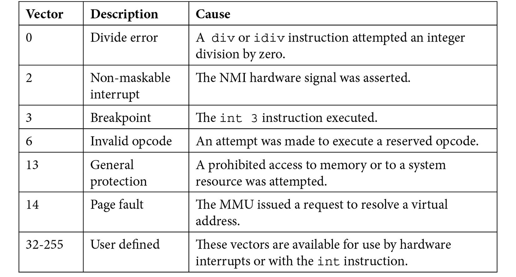
These are some details of interest related to the interrupts and exceptions listed in Table 9.1:
- The operation of the NMI input signal on vector 2 is similar to the NMI input of the 6502 processor, discussed in Chapter 3, Processor Elements.
- Although modern processors provide sophisticated, non-intrusive breakpoint capabilities, the x86 architecture retains the breakpoint facility provided by the int 3 instruction from the early days of 8086. As we saw in Chapter 3, Processor Elements, the mechanism used by 6502 software debuggers to break program execution at a specified address is to temporarily replace the opcode at the break location with the 6502 BRK opcode. When execution reaches that location, the BRK handler takes control to allow user interaction with the system. The int 3 instruction in the x86 architecture functions in the same manner. In fact, unlike the x86 int instruction used with any of the other vector numbers, the int 3 instruction is implemented as a single-byte opcode, with the value CCh. A software interrupt to a different vector, such as int 32, is a two-byte instruction. The int 3 instruction enables breakpoint insertion by replacing a single byte of code with the value CCh.
- Vector 13, the general protection exception handler, activates on any attempt by an application to access memory or a system resource not allocated for its use. In 32-bit and 64-bit operating systems, by default, the system-provided handler for this vector terminates the running application and displays an error message.
- Vector 14, the page fault handler, activates when an application attempts to access a page that is not present in physical memory. The handler attempts to locate the referenced page, which may be in a disk file or in the system swap file, loads the page into memory, updates the virtual-to-physical translation tables, and restarts the instruction that triggered the exception.
To summarize, hardware interrupts are initiated by I/O devices in need of data transfers or other types of servicing. System exceptions occur when the execution of an instruction sequence must be paused to handle a condition such as a page fault or attempted unauthorized access.
Hardware interrupts and system exceptions tend to occur at random times relative to the ongoing execution of program code, while behavior related to software-generated exceptions is generally repeatable if the same code executes again while operating on the same data.
While some exceptions, such as a general protection fault, result in the termination of the process causing the exception, most interrupts and exceptions end with the interrupted thread resuming execution after the interrupt or exception handler has completed its processing.
Programming language exceptions
Many programming languages provide a facility for performing exception handling within an application. It is important to understand that programming language exceptions are significantly different from the types of exceptions handled by the processor. Exceptions in programming languages generally relate to error conditions at a much higher level than exceptions handled by processor hardware.
For example, C++ will generate (or "throw," in C++ terminology) an exception when a memory allocation request fails. This is not the same type of exception as system exceptions handled at the processor level. Be careful not to confuse exceptions in high-level programming language with exceptions handled directly by the processor.
Protection rings
We can think of the protection strategy employed by modern processors and operating systems as similar in significant ways to the defenses implemented in the designs of medieval castles. A castle usually has a high wall surrounding the castle grounds, sometimes enhanced by the presence of a moat. This outer wall has a small number of well-defended access points, each of which is fortified against intruders by mechanisms such as drawbridges and around-the-clock guard details. Within the castle compound, the castle itself has sturdy walls and a small number of well-defended access points, further limiting access to the most sensitive areas.
The most privileged members of the castle hierarchy enjoy unrestricted access in and out of the castle and the outer wall. Less privileged members of the society may have authorization to pass inward through the outer wall but are prohibited from accessing the castle directly. The least privileged members of the local population are prohibited from entering the castle under most conditions and may have to accept limitations on what they can do on occasions when they are granted access, such as being permitted to access only specified public areas.
The protections provided by this strategy can be represented as concentric rings, with the highest privilege required to access the innermost rings, while the outer ring represents the area requiring the least privilege, as shown in this figure:

Figure 9.1: Protection ring example
This protection strategy contains three privilege levels that determine the types of access available to each individual in the system. Ring 0 requires the highest privilege level, while ring 2 requires no special privilege.
Modern processors and the operating systems that run on them use a very similar approach to prevent unauthorized access to critical resources, while granting unprivileged users access to system capabilities approved for their use.
Although, in principle, it is possible to provide multiple intermediate levels between the highest and lowest privileged rings, most modern computer architectures implement just two rings: a privileged ring, called the kernel or supervisor, and an unprivileged user ring. Some operating systems implement an intermediate ring containing device drivers, which grants access to the resources required to interact with I/O devices, but does not provide the unfettered system-wide access of the kernel ring.
One reason operating systems such as Windows and Linux support only two privilege rings is because these systems have a design goal of portability across different processor architectures. Some processors support only two privilege rings, while others support a greater number. A portable operating system cannot implement more than two privilege rings if any of the underlying processor architectures do not support the desired number of rings. The x86 architecture, for example, supports up to four rings, but only two of those (ring 0, the most privileged, and ring 3, the least privileged) are used by Windows and Linux.
The following figure represents the ring organization of most operating systems running on the x86 architecture:

Figure 9.2: Protection rings in x86 processors
This ring-based privilege management system is the primary reason the infamous Windows "Blue Screen of Death," which was common in the 1990s, appears so rarely for users of recent versions of Windows. User applications such as web browsers, email clients, and word processors will, on occasion, experience problems that cause the programs to crash. By virtue of the privilege enforcement mechanisms provided by operating systems such as Windows, Linux, macOS, and Android, the crash of an individual application is contained by the operating system, preventing the crash from affecting the operating system itself or any other program running on the system (at least, those programs that aren't dependent upon the program that crashed for their correct operation).
Following an application crash, the operating system cleans up any resources in use by the crashed program, including allocated memory pages and open files. This allows computer systems such as web server hosts to remain operational continuously for hundreds of days, despite the occasional crashes and restarts of software applications running on them.
In addition to protecting against application crashes, ring-based privilege control provides substantial security benefits against malicious actors. One type of attack a hacker might attempt is to insert some code into a system module that runs in ring 0. This insertion could occur in an executable file on disk, or the attacker may try to modify kernel code while it is running in memory. If successful, the attacker could then use this code to access data anywhere in the system because it is running in ring 0.
While achieving success with this type of attack is by no means impossible, modern processors and operating systems have implemented an extensive array of security measures and repaired many vulnerabilities found in earlier versions of operating systems. When system administrators and users take full advantage of the ring-based security measures available in modern computer systems, there are very few feasible paths an attacker can take to access protected data. In fact, in most cases, a key element of successful hacks that make it into the news is a human-related security breakdown exploited by the attacker.
Supervisor mode and user mode
In a two-level protection ring hierarchy, the protection level of the currently executing thread is typically represented by a bit in a register. When operating in ring 0, the supervisor mode bit is 1, and when operating in user mode (ring 3 on x86) the supervisor mode bit is 0. The supervisor mode bit can only be modified by code running in supervisor mode.
The state of the supervisor mode bit determines which instructions are available for execution by the thread. Instructions that could interfere with system operation, such as the x86 hlt instruction, which halts processor instruction execution, are unavailable in user mode. Any attempt to execute a prohibited instruction results in a general protection fault. In user mode, access by user applications to system memory regions and the memory allocated to other users is prohibited. In supervisor mode, all instructions are available for execution and all memory regions are accessible.
In the castle analogy, the supervisor mode bit represents the identification presented to the castle guards that enables access to the castle grounds and to the castle itself. When set, the supervisor mode bit provides the keys to the kingdom.
System calls
All code belonging to the kernel and device drivers runs in ring 0, always. All user code runs in ring 3, always, even for users with enhanced operating system privileges such as system administrators. Code running in ring 3 is strictly controlled by the system and cannot directly do anything that involves allocating memory, opening a file, displaying information to the screen, or interacting with an I/O device. To access any of those system features, ring 3 user code must make a service request to the kernel.
The kernel service request must first pass through a gate (just like visitors entering our castle!) where the type of operation being requested, as well as any associated parameters, are scrutinized and validated before the execution of the operation is allowed to proceed. The code performing the requested operation runs in supervisor mode at ring 0 and, when complete, returns control to the user mode calling routine in ring 3.
In early versions of Windows (prior to Windows XP), an application used the software interrupt mechanism with vector 2eh to request system services. The system call protocol involved placing the parameters required by the requested service into processor registers and executing the int 2eh instruction, triggering a software interrupt. The handler would run in supervisor mode, resulting in a transition from ring 3 to ring 0. Upon completion of the handler, the system returned to ring 3 at the instruction following int 2eh.
One problem with the use of the int 2eh mechanism for requesting kernel services is that it is not very efficient. In fact, it takes over 1,000 processor clock cycles to get from the point at which the int 2eh instruction executes to the kernel code that actually begins to handle the exception. A busy system may request kernel services thousands of times per second.
To address this inefficiency, Intel implemented the sysenter and sysexit instructions in the x86 architecture beginning with the Pentium II processor in 1997. The purpose of these instructions is to accelerate the process of calling from ring 3 to ring 0, and later returning to ring 3. By using these instructions instead of int 2eh, entry into and exit from kernel mode speeds up by about a factor of three.
Around the time Intel began producing processors with the sysenter and sysexit instructions, AMD released the syscall and sysret instructions in their processor architectures, with the same performance objective. Unfortunately, the instructions in the Intel and AMD processor architectures are not compatible, which leads to a requirement for operating systems to differentiate between architectures when using accelerated kernel calling instructions.
Next, we will look at the data formats and operations associated with floating-point mathematical processing.
Floating-point mathematics
Modern processors usually support integer data types in widths of 8, 16, 32, and 64 bits. Some smaller embedded processors may not directly support 64-bit or even 32-bit integers, while more sophisticated devices may support 128-bit integers. Integer data types are appropriate for use in a wide range of applications, but many areas of computing, particularly in the fields of science, engineering, and navigation, require the ability to represent fractional numbers with a high degree of accuracy.
As a simple example of the limitations of integer mathematics, suppose you need to divide 5 by 3. On a computer restricted to using integers, you can perform an integer calculation of this expression as follows, in C++:
#include <iostream>
int main(void)
{
int a = 5;
int b = 3;
int c = a / b;
std::cout << "c = " << c << std::endl;
return 0;
}
This program produces the following output:
c = 1
If you punch this expression into your pocket calculator, you'll find the printed result is not very close to the actual result, which is approximately 1.6667. In computing applications where accurate calculations involving real numbers are required, the use of floating-point mathematics provides a practical solution.
Mathematically, the set of real numbers consists of all of the numbers, including all integers and fractions, along the number line from negative infinity to positive infinity. There is no limit to the number of digits in the integer and fractional parts of a real number.
Given the finite storage available in even the largest computer, it is clearly not possible to represent the entire range of real numbers in computer programs. A compromise is required if we are to represent real numbers in a useful manner. The compromise implemented nearly universally is to represent real numbers in terms of a mantissa and exponent.
In areas of study involving the mathematics of very large or very small numbers, it is common to represent such numbers in terms of a mantissa and an exponent. For example, in physics, the gravitational constant ![]() . In this format, the mantissa represents the nonzero digits of the number after multiplication by a scaling factor that places those digits within a convenient range. The exponent represents the scaling factor by which the mantissa must be multiplied to produce the actual value.
. In this format, the mantissa represents the nonzero digits of the number after multiplication by a scaling factor that places those digits within a convenient range. The exponent represents the scaling factor by which the mantissa must be multiplied to produce the actual value.
In this example, the mantissa is 6.674 and the exponent is -11. This example uses a base-10 mantissa, which is convenient for manual calculation because multiplication by the scale factor 10-11 can be performed by simply moving the position of the mantissa decimal point. In this example, an exponent of -11 requires moving the decimal point 11 places to the left, resulting in the equivalent number 0.00000000006674. The use of floating-point notation avoids the error-prone use of lengthy sequences of zeros and allows both extremely large and very tiny numbers to be represented in a compact notation.
Any number along the real number line can be represented in floating-point notation. However, there can be no limit on the number of digits in the mantissa or exponent of the notation if the goal is to truly represent all real numbers.
In computer representations of floating-point numbers, both the mantissa and exponent are limited to predefined bit widths. These ranges have been chosen to fit floating-point numbers within standard data widths, typically 32 or 64 bits, while providing an adequate number of mantissa and exponent digits for a wide variety of applications.
Increasing the number of mantissa digits increases the precision of the numerical values representable in floating-point format. Increasing the number of exponent digits increases the range of numbers that can be represented. Because of the finite lengths of the mantissa and exponent, the result of a floating-point calculation often does not precisely equal the actual real-valued result. Instead, the best we can expect is that the floating-point result will be the nearest representable value to the correct result.
Modern processors commonly support 32-bit and 64-bit representations of floating-point numbers. Rather than the base-10 exponents described on the preceding page, computers work with base-2 exponents. The general format of a computer floating-point number is as follows:
![]()
The sign is simply +1 or -1. In the binary representation, a positive number has a sign bit of 0 and a negative number has a sign bit of 1. Having separated the sign from the rest of the number, the remaining value is nonnegative. For any value other than zero (which is handled as a special case), this number can be scaled into the range of greater than or equal to 1 and less than 2 by multiplying it by some power of 2.
Continuing the example of the gravitational constant, because the sign is +1, the value after removing the sign is unchanged: ![]() . The mantissa for this number can be scaled into the range
. The mantissa for this number can be scaled into the range ![]() , where m represents the mantissa, by multiplying by 234. The result of this scaling is:
, where m represents the mantissa, by multiplying by 234. The result of this scaling is:
![]()
We multiplied the original number by 234 to get the mantissa into the desired range, so the floating-point representation of the number must be multiplied by 2-34 to undo the scaling operation.
Since our computer operates on binary numbers, we must next convert the mantissa to a binary representation. The format used in floating-point processing is to represent the range between 1 and 2 with an unsigned integer.
For example, if we assume the binary mantissa is 16 bits wide, the mantissa of 1.0 is represented by 0000h and the value just below 2.0 (actually 1.99998474) is represented by FFFFh. A decimal mantissa m is converted to a 16-bit binary mantissa using the expression ![]() and rounding the result to the nearest integer. A 16-bit binary mantissa m is converted to decimal with the expression
and rounding the result to the nearest integer. A 16-bit binary mantissa m is converted to decimal with the expression ![]() .
.
In our example, the decimal mantissa of 1.1465845 converts to a 16-bit binary mantissa of 0010010110000111b, or 2587h.
Using the scaling procedure described in the preceding section, floating-point numbers can be represented in binary form with any desired bit widths for the mantissa and exponent. For the purposes of compatibility, it is helpful to define a limited number of binary floating-point formats capable of supporting a wide variety of use cases and to adopt those formats industry-wide.
The IEEE 754 standard for the computer representation of floating-point numbers was adopted in 1985 for this reason. Before looking at the standard, we'll explore the design of the Intel 8087 floating-point coprocessor, which was the source of many of the concepts later enshrined in the IEEE 754 standard.
The 8087 floating-point coprocessor
Modern processors with floating-point hardware generally implement a set of instructions for floating-point computations and perform these operations in a dedicated functional unit. In a superscalar processor, the main processor core continues to execute other categories of instructions while the floating-point unit (FPU) executes floating-point calculations in parallel.
Recall from Chapter 1, Introducting Computer Architecture, that the original IBM PC of 1981 contained a socket for an 8087 floating-point coprocessor. The 8087 performs floating-point computations in hardware at speeds roughly 100 times faster than a functionally equivalent software implementation running on the host processor. Because installation of the 8087 was optional, most PC software applications that wished to take advantage of its capabilities first tested for the presence of the 8087 and, if it was not found, reverted to a library of much slower floating-point code.
The 8087 supports the following data types for numeric processing:
- 16-bit two's complement integer
- 32-bit two's complement integer
- 64-bit two's complement integer
- 18-digit signed packed binary coded decimal (BCD)
- 32-bit signed short real with a 24-bit mantissa and an 8-bit exponent
- 64-bit signed long real with a 53-bit mantissa and an 11-bit exponent
- 80-bit signed temporary real with a 64-bit mantissa and a 15-bit exponent
Each data type is stored as a series of bytes in memory. The formats used for the real data types are shown in the following figure:
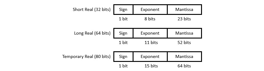
Figure 9.3: 8087 coprocessor floating-point data formats
The short and long real formats use an implied 1 bit as the most significant bit of the mantissa, and do not include this bit in their binary representations. As a special case, the value zero is represented in these formats by setting both the mantissa and exponent to zero.
The temporary real format is used internally in the 8087 to store intermediate results. This format has extended precision in comparison to the long real format to minimize the propagation of rounding errors over a series of calculations.
Each of the real number formats can be represented as ![]() , where S is the sign bit, E is the exponent, and m is the mantissa. This bias is 127 in the short real format, 1023 in the long real format, and 16,383 in the temporary real format. The bias term converts the unsigned integer stored in the exponent field to a signed value.
, where S is the sign bit, E is the exponent, and m is the mantissa. This bias is 127 in the short real format, 1023 in the long real format, and 16,383 in the temporary real format. The bias term converts the unsigned integer stored in the exponent field to a signed value.
Our example real number, G, which has a decimal mantissa of 1.1465845 and a binary scale of 2-34, is represented with a sign bit of 0, an exponent of (-34 + 127) = 5Dh, and a mantissa of ![]() . Combining all three components, the 32-bit representation of
. Combining all three components, the 32-bit representation of ![]() is
is![]() .
.
The 8087 adds 68 opcode mnemonics to the 8086/8088 instruction set for performing arithmetic, trigonometric, exponential, and logarithmic functions. In a PC program using the 8087, the code consists of a single stream of 8088 and 8087 instructions retrieved in the usual sequential manner by the 8088 host processor. The 8087 passively monitors the address and data buses as the host processor executes instructions and only becomes active when an 8087 opcode appears. The 8088 treats 8087 instructions as no-operation (or nop) instructions and ignores them.
When the 8087 begins executing an instruction, it is able to take control of the host bus to transfer data between its internal registers and system memory using DMA cycles. The 8087 and 8088 do not directly transfer data between themselves, and can only share data by storing it in memory for use by the other processor. 8087 instruction execution proceeds independent of the 8088, making an 8087-equipped PC a truly parallel processing system. The 8087 has a BUSY output signal for use by the 8088 host processor to determine whether the 8087 is currently processing an instruction.
When the 8088 requires the results of an 8087 operation, the 8088 must wait for the 8087 BUSY signal to de-assert, at which point the 8088 is free to access the memory locations containing the output of the 8087 instruction.
The IEEE 754 floating-point standard
The most widely used formats for representing floating-point numbers in modern computer systems are those defined in the IEEE 754 standard. IEEE, the Institute of Electrical and Electronic Engineers, publishes a wide variety of standards related to electricity, electronics, and computing. The original version of the IEEE 754 standard was adopted in 1985, based largely on the data types and mathematical operations of the Intel 8087.
The 8087 was not entirely compliant with the initial IEEE 754 standard, which was published several years after the introduction of the 8087. Later Intel floating-point coprocessors, beginning with the 80387 in 1987, were fully standard-compliant. Today's 32-bit and 64-bit processors generally implement an IEEE 754-compliant floating-point coprocessor on the same silicon die as the main processor.
The IEEE 754 standard was updated in 2008 and again in 2019. The current version is IEEE 754-2019 and contains definitions for base-2 floating-point number formats with bit widths of 16, 32, 64, 128, and 256 bits. It also contains base-10 floating-point number formats with bit widths of 32, 64, and 128 bits. The 32-bit and 64-bit base-2 floating-point formats are generally supported in programming languages that include floating-point operations. Support for the remaining IEEE 754 data types tends to be more limited and non-standardized across processors, programming languages, and operating systems.
The next section presents features that many modern processor architectures implement to manage system power consumption.
Power management
For users of portable battery-powered devices such as smartphones, tablets, and laptop computers, the ability to operate for long time periods without recharging is an important feature. Designers of portable systems place great emphasis on ensuring battery power consumption is minimized under all operating conditions. Some techniques designers use to reduce power consumption are as follows:
- Placing idle subsystems in a low-power state, or turning them off completely when they are not needed. This solution may not be possible for peripherals that must be available to respond to incoming requests, such as network interfaces.
- Reducing integrated circuit supply voltages and clock speeds during periods when execution speed is not critical.
- When possible, saving system state information and turning the processor power off completely. Users of laptop computers are familiar with two options for reducing power consumption when the system is not in use: standby and hibernate. In standby mode, system RAM continues to be powered while the rest of the system is turned off. Standby mode enables very fast startup when the user resumes using the system. This responsiveness comes at a cost: keeping RAM powered consumes a significant amount of power. In hibernate mode, the entire system state is written to disk storage and the system powers down completely. Hibernate mode requires essentially zero power, though it normally takes quite a bit longer than standby mode to resume operation.
- When periodic processing is required, such as in real-time applications, place the processor in a low-power state each time processing completes. The processor remains in that state until a timer interrupt wakes the processor for the next iteration. Many embedded processors provide a low-power idle mode in which the instruction pipeline is halted, but remains ready to instantly resume execution in response to an interrupt. Some RTOS implementations support this concept by idling the processor when all tasks are blocked waiting for an interrupt or other event.
Smartphones and other battery-powered devices make extensive use of all of these methods to drive battery usage to a minimum while remaining instantly responsive to user inputs and to external inputs such as incoming calls and social media notifications.
Modern processors in high-performance computers and in embedded devices generally support the ability to adjust processor clock speed during code execution, and in some cases provide the ability to alter the processor power supply voltage as well. This combination of power management techniques is addressed in the next section.
Dynamic voltage frequency scaling
Optimization of processor clock frequency and supply voltage to minimize power consumption is called dynamic voltage frequency scaling (DVFS). When performing DVFS, a processor regularly evaluates the performance requirements of its current operating state and adjusts the processor clock frequency and power supply voltage to minimize battery usage while continuing to perform at an acceptable level.
In a CMOS chip containing a large number of transistors, a reasonable estimate of power consumption is 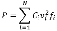 . In this expression, P represents the total power consumption of the chip, which contains N MOS transistors. Ci is the capacitance driven by the ith transistor, vi is the transistor's supply voltage, and fi is its operating frequency.
Examining this formula, we see that circuit power consumption is proportional to the square of the supply voltage, and is directly proportional to capacitance and operating frequency. Because capacitance in the circuit plays a significant role in power consumption, it is beneficial to implement the device using a fabrication process that reduces the size of circuit gates, keeping the capacitance to a minimum. This is one reason a transition to an integrated circuit fabrication process supporting smaller feature sizes results in devices with reduced power consumption.
DVFS attempts to minimize overall power consumption by reducing both the supply voltage and processor clock frequency as much as possible, at all times.
Reducing the circuit supply voltage can provide a dramatic reduction in power consumption. However, any reduction of the processor supply voltage must be carefully coordinated with adjustments to the clock frequency. When the supply voltage is reduced, CMOS transistors switch more slowly. This is because the capacitance driven by each transistor remains unchanged, but that capacitance charges and discharges at a slower rate because there is less voltage driving the charge/discharge process. As the system voltage is reduced, the clock frequency must be reduced in tandem for the circuit to function properly.
Recalling the hydraulic system analogy from Chapter 2, Digital Logic, the effect of reducing the CMOS supply voltage is equivalent to reducing the water pressure that fills the balloon attached to the side of the pipe: with reduced system pressure, the balloon fills more slowly.
Reducing the processor supply voltage also reduces the circuit's noise immunity. When this happens, it becomes easier for external interference, such as the electrical field emanating from a motor starting up in a household appliance, to disrupt the internal operation of the processor. Any processor voltage reduction must be limited to ensure continued reliable operation.
Reducing the processor clock frequency (in addition to any clock slowing required by supply voltage reduction) reduces power consumption by an approximately proportional amount. Reducing the operating frequency also increases system reliability because each gate transition has more time to propagate and reach its final state before being latched by the gates it is driving.
A complex embedded device such as a smartphone may need to transition rapidly between higher and lower power states as its various inputs stimulate it with user actions, timer-triggered events, and information arriving over wireless connections. While it is beneficial for the system to nimbly switch between lower and higher power modes as circumstances change, it is also important to limit the rate at which such transitions occur because the mere act of switching between power modes consumes some power itself.
Users expect their computers and other sophisticated digital devices to consume no more power than absolutely necessary, and they also expect those systems to be secure. The next section introduces the key aspects of system security management.
System security management
We have seen how the separation of privilege levels between kernel and user modes supports the effective separation of applications started up by one user from those of other users and from system processes. This represents security at the level of executing software. This is fine as far as it goes, but what about systems that must remain secure even when untrusted users have unrestricted physical access to them? Additional measures must be implemented at the hardware level to prevent curious or malicious users from accessing protected code, data, and hardware resources.
Before getting into the details of hardware-level security features, it is helpful to list some of the categories of information and other resources that must be protected in digital systems:
- Personal information: Information such as government identification numbers, passwords for accessing web accounts, contact lists, emails, and text messages must be protected even if a portable device containing that information is lost or stolen.
- Business information: Trade secrets, customer lists, research products, and strategic plans are some categories of confidential business data that may have great value in the hands of competitors or criminals. Businesses also collect a great deal of personal information about their customers and are required to undertake substantial efforts to keep this information secure.
- Government information: Government organizations maintain a great deal of personal information about their citizens and must ensure it can only be used for authorized purposes. Governments also develop a vast quantity of information related to national security that requires extensive security protocols.
Beyond the obvious physical security measures of storing sensitive information in a sturdy, access-controlled facility with effective alarm systems, a number of measures can be taken to ensure a system is secure against a wide variety of attacks.
Consider the smartphone. A technically capable individual or organization may be able to disassemble the phone's case and gain access to the circuit-level hardware. If this person is able to monitor the external electrical signals of the processor and its communication paths to other system components, what kinds of information might be gathered? The answer depends on the types and quantity of hardware security implemented in the system design.
A first step in secure system design is to avoid inserting security vulnerabilities during development. During the development of a system containing an embedded processor, it is quite useful to provide a hardware debugger interface. A hardware debugger enables the connection of a PC to the device using a special interface cable. Using this connection, developers can reprogram flash memory, set breakpoints in the code, display the values of registers and variables, and single-step through code. If the debugger connection remains in the circuit board in the released version of the design, it may be possible for users to connect their own debugger to the system and work with it in the same manner as the developers.
This is clearly undesirable for any system intended to operate securely. Because the ability to connect a debugger continues to be quite useful even after a product is released, developers sometimes attempt to leave the debugger signals present in the circuit but camouflage them in some manner to make their functions less obvious. While this approach may be effective to some degree, dedicated hackers have demonstrated the ability to ferret out the presence of even the most cleverly disguised debugging interfaces and leverage those interfaces to access the processor's internals. Leaving an accessible hardware debugging interface present in a released product is a serious security vulnerability.
Many processor vendors have begun implementing security features to prevent even dedicated, technically capable attackers from breaching processor protections. To be effective, system developers must enable and fully leverage these capabilities in their system designs. Some examples of security technologies include the following:
- Password-protected hardware debugger interface: Some processor families support the addition of a password to the standard hardware debugging interface. In these systems, an initial handshake must take place in which the connected system provides a strong password (such as a 256-bit number) before the processor enables debug functionality. This is an effective approach that retains the ability to securely troubleshoot issues that arise after the product is released.
- Internal encryption engine with key storage: Some processors provide encryption and decryption capabilities and store secret keys for use during operation. The keys must be stored in the processor during system manufacture and are not externally accessible after they have been stored. This combination of encryption engine and stored keys allows secure communication with authorized external devices. The use of high-speed, hardware-based encryption and decryption capabilities allows secure full-speed communication between physically separated subsystems such as those within an automobile.
- Device memory protection: Many processor families provide several options for the protection of memory regions. For example, a ROM bank containing code can be locked after programming to ensure it cannot be reprogrammed at a later time. Code regions can also be blocked from being read as data while still allowing access for execution. Processors that lack a full memory management unit often have a subsystem called the memory protection unit (MPU) to manage the security requirements of the various processor memory regions.
It is not sufficient to design in a standard set of security features and assume hackers will be unable to penetrate those defenses. Attackers have demonstrated extraordinary cleverness and will use any avenue to gain insight into the inner workings of a system they find interesting. Some areas to consider beyond the standard security techniques are as follows:
- Power, timing, and emission analysis: By using fine-grained monitoring of system power consumption, the timing of external signal activity, or even the radio frequency emissions generated during algorithm execution, it may be possible to reverse engineer the activities going on within the processor. Attacks based on these methods have been successful at extracting secret encryption keys during cryptographic algorithm execution, for example.
- Power disruption: Intentionally inducing power supply voltage fluctuations or dropouts during system power-up or operation has been shown to leave many systems in a vulnerable state in which some security features are inactive. A robust system design must anticipate such behavior, whether natural or intentional, and revert to a safe, secure state whenever the power supply is not performing within established parameters.
- Physical alteration: An attacker may replace some components in the system in an attempt to gain control. For example, replacing a boot ROM device may allow the system to operate normally while also enabling the attacker to gain unrestricted internal access using code in the replacement ROM. A growing number of processor families support the use of digital signatures to verify the authenticity of ROM code. To check the contents of the ROM device, the processor runs a hash algorithm, which is a complex mathematical calculation on the ROM data. The results of the hash algorithm (the signature) must match the signature preloaded in the processor before the ROM code will be executed. The hash algorithm is designed to make it essentially impossible to alter the ROM data content while still producing the expected signature. For good measure, the ROM data content can also be encrypted, which prevents the attacker from analyzing the code it contains.
This section has listed some fundamental approaches to implementing security in digital devices, and briefly examined some of the more esoteric security vulnerabilities that have been exploited by dedicated attackers. The design of a secure system must begin with a firm grounding in the basics of security, but also requires some ingenuity in considering the many ways a determined attacker may attempt to breach system security.
Summary
This chapter built upon the preceding chapters, which presented the basic aspects of computer architecture and architectural variations addressing domain-specific requirements. We focused here on extensions commonly implemented at the processor instruction set level to provide additional system capabilities beyond generic computing requirements.
You should now have a good understanding of privileged processor modes and how they are used in multiprocessing and multiuser contexts, the concepts of floating-point processors and instruction sets, techniques for power management in battery-powered devices, and processor features intended to enhance system security.
This background has prepared us for the next chapter, in which we will, the most popular processor architectures and instruction sets currently used in personal computing, business computing, and in smart portable devices. These architectures are the x86, the x64, and the 32-bit and 64-bit variants of ARM.
Exercises
- Using a programming language that allows access to the byte representation of floating-point data types (such as C or C++), write a function that accepts a 32-bit single-precision value as input. Extract the sign, exponent, and mantissa from the bytes of the floating-point value and display them. Remove the bias term from the exponent before displaying its value and display the mantissa as a decimal number. Test the program with the values 0, -0, 1, -1, 6.674e-11, 1.0e38, 1.0e39, 1.0e-38, and 1.0e-39. The numeric values listed here containing e are using the C/C++ text representation of floating-point numbers. For example, 6.674e-11 means 6.674 x 10⁻¹¹
- Modify the program from Exercise 1 to also accept a double-precision floating-point value, and print the sign, exponent (with the bias removed), and mantissa from the value. Test it with the same input values as in Exercise 1, and also with the values 1.0e308, 1.0e309, 1.0e-308, and 1.0e-309.
- Search the Internet for information about the NXP Semiconductors i.MX RT1060 processor family. Download the product family datasheet and answer the following questions about these processors.
- Do the i.MX RT1060 processors support the concept of supervisor mode instruction execution? Explain your answer.
- Do the i.MX RT1060 processors support the concept of paged virtual memory? Explain your answer.
- Do the i.MX RT1060 processors support floating-point operations in hardware? Explain your answer.
- What power management features do the i.MX RT1060 processors support?
- What security features do the i.MX RT1060 processors support?