
In the previous four chapters, you learned about the architecture and processing capabilities of AVX. These chapters explicated AVX’s register sets, data types, and instructions. They also included numerous source code examples that illustrated how to perform scalar floating-point arithmetic, packed floating-point computations, and packed integer calculations. Many of the packed floating-point and packed integer source code examples exemplified important SIMD programming strategies and techniques whose exploitation often results in faster executing code.
This chapter explains the architecture and computational resources of Advanced Vector Extensions 2 (AVX2). You’ll learn about AVX2’s augmented capabilities for processing packed floating-point and packed integer operands. You’ll also review important details regarding recent x86 platform instruction set extensions, including half-precision floating-point conversions, fused-multiply-add (FMA) operations, and new general-purpose register instructions.
The material presented in this chapter assumes that you have a solid understanding of AVX. If you feel that your understanding of AVX’s register sets, data types, or SIMD processing capabilities is lacking in any way, you may want to review the relevant sections in the previous chapters before proceeding.
AVX2 Execution Environment
AVX2 uses the same YMM and XMM register sets as AVX (see Figure 4-6). AVX2 also uses the MXCSR control-status register to signal floating-point arithmetic errors, configure rounding options, and control the generation of floating-point exceptions (see Figure 4-11). Like AVX, AVX2 supports floating-point SIMD operations using 128-bit or 256-bit wide operands containing either single-precision or double-precision values. AVX2 extends the packed integer processing capabilities of AVX to include both 128-bit and 256-bit wide operands (AVX only supports 128-bit wide integer operands). When used with a 256-bit wide packed integer operand, an AVX2 instruction can simultaneously process 32 byte, 16 word, 8 doubleword, or 4 quadword values. AVX2 also adds a number of useful instructions that administer packed floating-point and packed integer operands. You’ll learn more about these instructions later in this chapter.
AVX2 instructions use the same instruction syntax as AVX. Most AVX2 instructions employ a three-operand format that consists of two source operands and one destination operand. Nearly all AVX2 instruction source operands are non-destructive. This means that source operands are not modified during instruction execution, except in cases where the destination operand register is the same as one of the source operand registers. A small set of AVX2 instructions employ a third immediate source operand that’s typically used as a control mask.
The alignment requirements for AVX2 operands in memory are the same as AVX. Except for data transfer instructions that explicitly reference an aligned operand in memory (e.g., vmovdqa, vmovap[d|s], etc.), proper alignment of an AVX2 operand in memory is not mandatory. However, 128-bit wide operands in memory should always be aligned to a 16-byte boundary whenever possible in order to maximize processing performance. Similarly, 256-bit wide operands should be aligned to a 32-byte boundary.
AVX2 Packed Floating-Point
Scale: The element size scale factor (1, 2, 4, or 8).
Index: A vector index register (XMM or YMM) that contains signed doubleword or signed quadword indices.
Base: A general-purpose register that points to the start of an array in memory.
Displacement: An optional fixed offset from the start of the array.
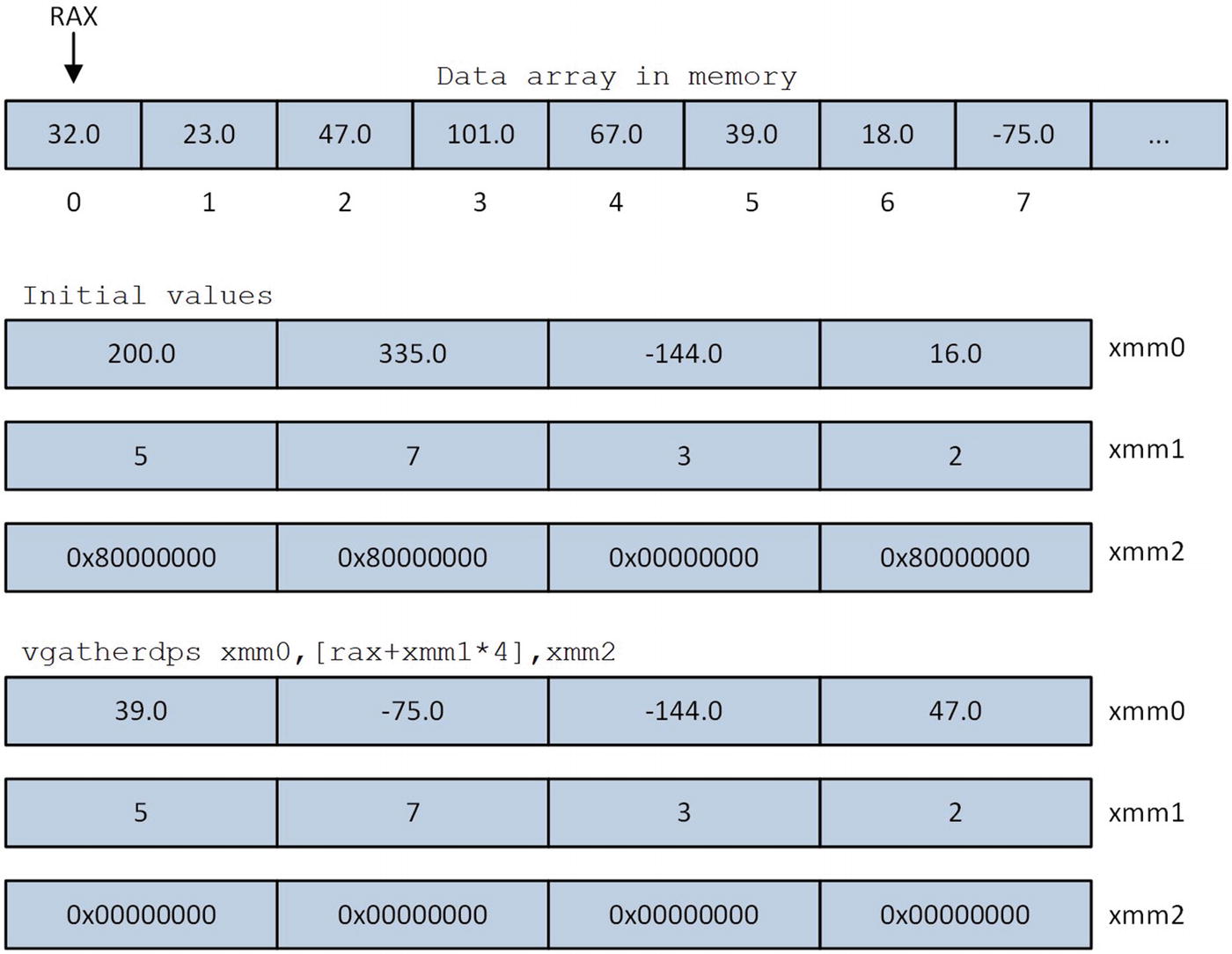
Illustration of the vgatherdps instruction execution
The destination operand and second source operand (the copy control mask) of a vgatherdp[d|s] or vgatherqp[d|s] instruction must be an XMM or YMM register. The first source operand specifies the VSIB components (i.e., base register, vector index register, scale factor, and optional displacement). The vgatherdp[d|s] or vgatherqp[d|s] instructions do not perform any checks for invalid indices. An invalid index is any vector index register value that directs a gather instruction to load an element from a memory location that’s outside the limits of the array. Using an invalid index will yield an incorrect result and possibly cause the processor to generate an exception.
The other notable AVX2 packed floating-point enhancement involves the vbroadcasts[d|s] instructions. On processors that support AVX2, the source operand for these instructions can be an XMM register (AVX only supports vbroadcasts[d|s] source operands in memory). When used in this manner, the vbroadcasts[d|s] instructions copy the low-order double-precision or single-precision floating-point element of an XMM register to each element position in the destination operand.
AVX2 Packed Integer
Summary of New AVX2 Packed Integer Instructions
Mnemonic | Description |
|---|---|
vbroadcasti128 | Broadcast 128 bits of integer data |
vextracti128 | Extract 128 bits of integer data |
vinserti128 | Insert 128 bits of integer data |
vpblendd | Blend packed doublewords |
vpbroadcast[b|w|d|q] | Broadcast integer value |
vperm2i128 | Permute 128-bit integer data |
vperm[d|q] | Permute packed integers |
vpgatherd[d|q] | Packed integer gather using signed doubleword indices |
vpgatherq[d|q] | Packed integer gather using signed quadword indices |
vpmaskmov[d|q] | Conditional packed integer data move |
vpsllv[d|q] | Left logical shift using individual element bit counts |
vpsravd | Right arithmetic shift using individual element bit counts |
vpsrlv[d|q] | Right logical shift using individual element bit counts |
The vpgatherd[d|q] and vpgatherq[d|q] instructions that are shown in Table 8-1 use the same VSIB memory addressing scheme as their floating-point counterparts.
X86 Instruction Set Extensions
Recent x86 Instruction Set Extensions
Instruction Set Extension | CPUID Feature Flag |
|---|---|
Enhanced unsigned integer addition | ADX |
Advanced bit manipulation (group 1) | BMI1 |
Advanced bit manipulation (group 2) | BMI2 |
Half-precision floating-point conversions | F16C |
Fused-multiply-add | FMA |
Count leading zero bits | LZCNT |
Count set bits | POPCNT |
The remainder of this section briefly describes the instruction set extensions that are shown in Table 8-2. Chapters 10 and 11 contain source code examples that illustrate how to use some of the instructions that are included in these extensions. Information regarding the instruction set extensions not shown in Table 8-2 can be found in the programming reference manuals published by AMD and Intel. Appendix A contains a list of these manuals.
Half-Precision Floating-Point
Half-Precision Floating-Point Conversion Instructions
Mnemonic | Description |
|---|---|
vcvtph2ps | Convert half-precision floating-point to single-precision floating-point |
vcvtps2ph | Convert single-precision floating-point to half-precision floating-point |
Fused-Multiply-Add (FMA)
Modern processors from both AMD and Intel also include instructions that perform FMA operations. A FMA instruction combines multiplication and addition (or subtraction) into a single operation. More specifically, a fused-multiply-add (or fused-multiply-subtract) calculation performs a floating-point multiplication followed by a floating-point addition (or subtraction) using a single rounding operation. For example, consider the expression d = b * c + a. Using standard floating-point arithmetic, the processor initially calculates the product b * c, which includes a rounding operation. This is followed by a floating-point addition computation that also includes a rounding operation. If the expression is evaluated using FMA arithmetic, the processor does not round the intermediate product b * c. Rounding is carried out only once using the calculated product-sum b * c + a. FMA instructions are often used to improve the performance and accuracy of multiply-accumulate computations such as dot products and matrix-vector multiplications. Many signal-processing algorithms also make extensive use of FMA operations.
FMA instruction mnemonics employ a three-digit operand-ordering scheme that specifies which operands to use for multiplication and addition (or subtraction). In this scheme, all three instruction operands are used as source operands. The first mnemonic digit specifies the source operand to use as the multiplicand; the second digit specifies the source operand to use as the multiplier; and the third digit specifies the source operand that is added to (or subtracted from) the product. For example, consider the instruction vfmadd132sd xmm4,xmm5,xmm6 (Fused Multiply-Add of Scalar Double-Precision Floating-Point Values). In this example, registers XMM4, XMM5, and XMM6 are source operands 1, 2, and 3, respectively. The vfmadd132sd instruction computes xmm4[63:0] * xmm6[63:0] + xmm5[63:0], rounds the product-sum according to the rounding mode specified by MXCSR.RC, and saves the final result to xmm4[63:0].
The x86 FMA instruction set extension supports operations using scalar or packed floating-point values, both single-precision and double-precision. Packed FMA operations can be performed using either the XMM or YMM registers. The XMM (YMM) registers support packed FMA calculations using two (four) double-precision or four (eight) single-precision floating-point values. Scalar FMA calculations are carried out using the XMM register set. For all FMA instructions, the first and second source operands must be a register. The third source operand can be a register or a memory location. If an FMA instruction uses an XMM register as a destination operand, the high-order 128 bits of the corresponding YMM register are set to zero. FMA instructions carry out their sole rounding operation using the mode that’s specified by MXCSR.RC, as explained in the previous paragraph.
Overview of FMA Instructions
Subgroup | Mnemonic | Operation |
|---|---|---|
VFMADD | vfmadd132[pd|ps|sd|ss] | des = src1 * src3 + src2 |
vfmadd213[pd|ps|sd|ss] | des = src2 * src1 + src3 | |
vfmadd231[pd|ps|sd|ss] | des = src2 * src3 + src1 | |
VFMSUB | vfmsub132[pd|ps|sd|ss] | des = src1 * src3 − src2 |
vfmsub213[pd|ps|sd|ss] | des = src2 * src1 − src3 | |
vfmsub231[pd|ps|sd|ss] | des = src2 * src3 − src1 | |
VFMADDSUB | vfmaddsub132[pd|ps] | des = src1 * src3 + src2 (odd elements) des = src1 * src3 − src2 (even elements) |
vfmaddsub213[pd|ps] | des = src2 * src1 + src3 (odd elements) des = src2 * src1 − src3 (even elements) | |
vfmaddsub231[pd|ps] | des = src2 * src3 + src1 (odd elements) des = src2 * src3 − src1 (even elements) | |
VFMSUBADD | vfmsubadd132[pd|ps] | des = src1 * src3 − src2 (odd elements) des = src1 * src3 + src2 (even elements) |
vfmsubadd213[pd|ps] | des = src2 * src1 − src3 (odd elements) des = src2 * src1 + src3 (even elements) | |
vfmsubadd231[pd|ps] | des = src2 * src3 − src1 (odd elements) des = src2 * src3 + src1 (even elements) | |
VFNMADD | vfnmadd132[pd|ps|sd|ss] | des = -(src1 * src3) + src2 |
vfnmadd213[pd|ps|sd|ss] | des = -(src2 * src1) + src3 | |
vfnmadd231[pd|ps|sd|ss] | des = -(src2 * src3) + src1 | |
VFNMSUB | vfnmsub132[pd|ps|sd|ss] | des = -(src1 * src3) − src2 |
vfnmsub213[pd|ps|sd|ss] | des = -(src2 * src1) − src3 | |
vfnmsub231[pd|ps|sd|ss] | des = -(src2 * src3) − src1 |
The FMA instructions that are shown in Table 8-4 are often identified as FMA3 instructions by many CPU feature detection utilities and online documentation sources. Some AMD processors also include supplemental FMA4 instructions, which carry out their FMA operations using three source operands and one destination operand (the three-digit operand ordering scheme is not used). These instructions are not shown in Table 8-4.
General-Purpose Register Instruction Set Extensions
Overview of ADX, BMI1, BMI2, LZCNT, and POPCNT Instructions
Mnemonic | CPUID Feature Flag | Description |
|---|---|---|
adcx | ADX | Unsigned integer addition with carry flag |
adox | ADX | Unsigned integer addition with overflow flag |
andn | BMI1 | Bitwise AND of inverted operand1 with operand2 |
bextr | BMI1 | Bitfield extract |
blsi | BMI1 | Extract lowest set bit |
blsmsk | BMI1 | Get mask up to lowest set bit |
blsr | BMI1 | Reset lowest set bit |
bzhi | BMI2 | Zero high bits |
lzcnt | LZCNT | Count number of leading zero bits |
mulx | BMI2 | Flagless unsigned integer multiplication |
pdep | BMI2 | Parallel bits deposit |
pext | BMI2 | Parallel bits extract |
popcnt | POPCNT | Count number of set bits |
rorx | BMI2 | Flagless rotate right |
sarx | BMI2 | Flagless arithmetic shift right |
shlx | BMI2 | Flagless logical shift left |
shrx | BMI2 | Flagless logical shift right |
tzcnt | BMI1 | Count number of trailing zero bits |
Summary
AVX2 uses the same register sets, data types, and instruction syntax as AVX.
AVX2 extends the packed integer processing capabilities of AVX to support operations using 256-bit wide operands.
AVX2 includes new packed integer processing instructions that perform broadcast, permute, and variable bit-shift operations.
The vgather[d|q]p[d|s] and vpgather[d|q][d|q] instructions load floating-point or integer values into an XMM or YMM register from non-contiguous locations in memory. These instructions use the VSIB addressing mode to carry out their operations.
The vcvtph2ps and vcvtps2ph instructions perform conversions between packed half-precision to single-precision floating-point values.
All FMA instructions execute a floating-point multiplication followed by a floating-point addition (or subtraction) using a single rounding operation. The x86 FMA instruction set extension supports a variety of FMA operations using both scalar and packed single-precision or double-precision floating-point values.
The ADX, BMI1, BMI2, LZCNT, and POPCNT instruction set extensions include instructions that support enhanced unsigned integer addition, advanced bit manipulation, and flagless shift and rotate operations.