
In the first three chapters of this book, you learned about the core x86-64 platform including its data types, general-purpose registers, and memory addressing modes. You also examined a cornucopia of sample code that illustrated the fundamentals of x86-64 assembly language programming, including basic operands, integer arithmetic, compare operations, conditional jumps, and manipulation of common data structures.
This chapter introduces Advanced Vector Extensions (AVX). It begins with a brief overview of AVX technologies and SIMD (Single Instruction Multiple Data) processing concepts. This is followed by an examination of the AVX execution environment that covers register sets, data types, and instruction syntax. The chapter also includes discussions of AVX’s scalar floating-point capabilities and its SIMD computational resources. The material presented in this chapter is relevant not only to AVX but also provides the necessary background information to understand AVX2 and AVX-512, which are explained in later chapters.
In the discussions that follow in this and subsequent chapters, the term x86-AVX is used to describe general characteristics and computing resources of Advanced Vector Extensions. The acronyms AVX, AXV2, and AVX-512 are employed when examining attributes or instructions related to a specific x86 feature set enhancement.
AVX Overview
AMD and Intel first incorporated AVX into their CPUs starting in 2011. AVX extends the packed single-precision and double-precision floating-point capabilities of x86-SSE from 128 bits to 256 bits. Unlike general-purpose register instructions, AVX instructions use a three-operand syntax that employs non-destructive source operands, which simplifies assembly language programming considerably. Programmers can use this new instruction syntax with packed 128-bit integer, packed 128-bit floating-point, and packed 256-bit floating-point operands. The three-operand instruction syntax can also be exploited to perform scalar single-precision and double-precision floating-point arithmetic.
Summary of x86-AVX Technologies
Feature | AVX | AVX2 | AVX-512 |
|---|---|---|---|
Three-operand syntax; non-destructive source operands | Yes | Yes | Yes |
SIMD operations using 128-bit packed integers | Yes | Yes | Yes |
SIMD operations using 256-bit packed integers | No | Yes | Yes |
SIMD operations using 512-bit packed integers | No | No | Yes |
SIMD operations using 128-bit packed SPFP, DPFP | Yes | Yes | Yes |
SIMD operations using 256-bit packed SPFP, DPFP | Yes | Yes | Yes |
SIMD operations using 512-bit packed SPFP, DPFP | No | No | Yes |
Scalar SPFP, DPFP arithmetic | Yes | Yes | Yes |
Enhanced SPFP, DPFP compare operations | Yes | Yes | Yes |
Basic SPFP, DPFP broadcast and permute | Yes | Yes | Yes |
Enhanced SPFP, DPFP broadcast and permute | No | Yes | Yes |
Packed integer broadcast | No | Yes | Yes |
Enhanced packed integer broadcast, compare, permute, conversions | No | No | Yes |
Instruction-level broadcast and rounding control | No | No | Yes |
Fused-multiply-add | No | Yes | Yes |
Data gather | No | Yes | Yes |
Data scatter | No | No | Yes |
Conditional execution and data merging using opmask registers | No | No | Yes |
It should be noted that fuse-multiply-add is a distinct x86 platform feature extension that was introduced in tandem with AVX2. A program must confirm the presence of this feature extension by testing the CPUID FMA feature flag before using any of the corresponding instructions. You’ll learn how to do this in Chapter 16. The remainder of this chapter focuses primarily on AVX. Chapters 8 and 12 discuss the particulars of AVX2 and AVX-512 in greater detail.
SIMD Programming Concepts

128-bit wide operand using distinct integers
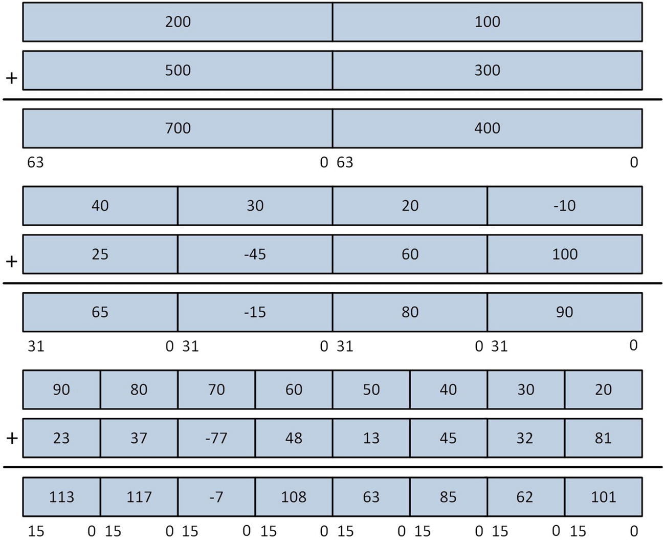
SIMD integer addition
Wraparound vs. Saturated Arithmetic
One extremely useful feature of x86-AVX technology is its support for saturated integer arithmetic. In saturated integer arithmetic, computational results are automatically clipped by the processor to prevent overflow and underflow conditions. This differs from normal wraparound integer arithmetic where an overflow or underflow result is retained (as you’ll soon see). Saturated arithmetic is handy when working with pixel values since it automatically clips values and eliminates the need to explicitly check the result of each pixel calculation for an overflow or underflow condition. X86-AVX includes instructions that perform saturated arithmetic using 8-bit and 16-bit integers, both signed and unsigned.
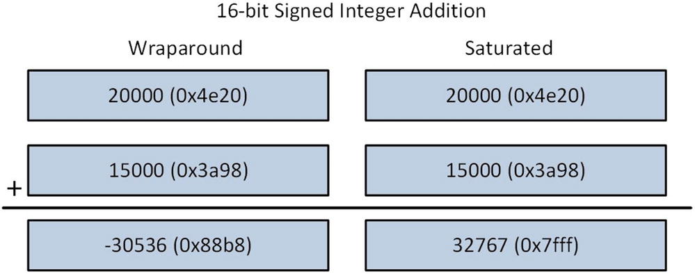
16-bit signed integer addition using wraparound and saturated arithmetic
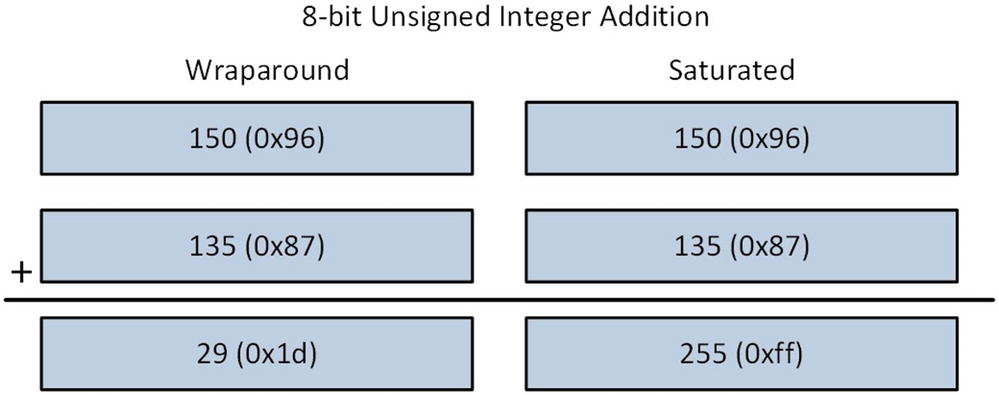
8-bit unsigned integer addition using wraparound and saturated arithmetic
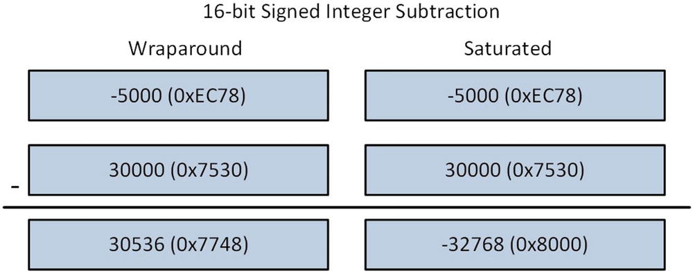
16-bit signed integer subtraction using wraparound and saturated arithmetic
Range Limits for Saturated Arithmetic
Integer Type | Lower Limit | Upper Limit |
|---|---|---|
8-bit signed | -128 (0x80) | +127 (0x7f) |
8-bit unsigned | 0 | +255 (0xff) |
16-bit signed | -32768 (0x8000) | +32767 (0x7fff) |
16-bit unsigned | 0 | +65535 (0xffff) |
AVX Execution Environment
In this section you’ll learn about the x86-AVX execution environment. Included are explanations of the AVX register set, its data types, and instruction syntax. As mentioned earlier, x86-AVX is an architectural enhancement that extends x86-SSE technology to support SIMD operations using either 256-bit or 128-bit wide operands. The material that’s presented in this section assumes no previous knowledge or experience with x86-SSE.
Register Set

AVX register set
The x86-AVX execution environment also includes a control-status register named MXCSR. This register contains status flags that facilitate the detection of error conditions caused by floating-point arithmetic operations. It also includes control bits that programs can use to enable or disable floating-point exceptions and specify rounding options. You’ll learn more about MXCSR register later in this chapter.
Data Types

AVX and AVX2 data types
AVX also includes instructions that use the XMM registers to perform SIMD operations using a variety of packed integer operands including bytes, words, doublewords, and quadwords. AVX2 extends the packed integer processing capabilities of AVX to the YMM registers and 256-bit wide operands in memory. Figure 4-7 also shows these data types.
Instruction Syntax
Perhaps the most noteworthy programming facet of x86-AVX is its use of a contemporary assembly language instruction syntax. Most x86-AVX instructions use a three-operand format that consists of two source operands and one destination operand. The general syntax that’s employed for x86-AVX instructions is InstrMnemonic DesOp,SrcOp1,SrcOp2. Here, InstrMnemonic signifies the instruction mnemonic, DesOp represents the destination operand, and SrcOp1 and SrcOp2 denote the source operands. A small subset of x86-AVX instructions employ one or three source operands along with a destination operand. Nearly all x86-AVX instruction source operands are non-destructive. This means source operands are not modified during instruction execution, except in cases where the destination operand register is the same as one of the source operand registers. The use of non-destructive source operands often results in simpler and slightly faster code since the number of register-to-register data transfers that a function must perform is reduced.
X86-AVX’s ability to support a three-operand instruction syntax is due to a new instruction-encoding prefix. The vector extension (VEX) prefix enables x86-AVX instructions to be encoded using a more efficient format than the prefixes used for x86-SSE instructions. The VEX prefix has also been used to add new general-purpose register instructions to the x86 platform. You’ll learn about these instructions in Chapter 8.
AVX Scalar Floating-Point
This section examines the scalar floating-point capabilities of AVX. It begins with a short explanation of some important floating-point concepts including data types, bit encodings, and special values. Software developers who understand these concepts are often able to improve the performance of algorithms that make heavy use of floating-point arithmetic and minimize potential floating-point errors. The AVX scalar floating-point registers are also explained in this section and this includes descriptions the XMM registers and the MXCSR control-status register. The section concludes with an overview of the AVX scalar floating-point instruction set.
Floating-Point Programming Concepts
In mathematics a real-number system depicts an infinite continuum of all possible positive and negative numbers including integers, rational numbers, and irrational numbers. Given their finite resources, modern computing architectures typically employ a floating-point system to approximate a real-number system. Like many other computing platforms, the x86’s floating-point system is based on the IEEE 754 standard for binary floating-point arithmetic. This standard includes specifications that define bit encodings, range limits, and precisions for scalar floating-point values. The IEEE 754 standard also specifies important details related to floating-point arithmetic operations, rounding rules, and numerical exceptions.

Memory organization of floating-point values
Floating-Point Size Parameters
Parameter | Single-Precision | Double-Precision |
|---|---|---|
Total width | 32 bits | 64 bits |
Significand width | 23 bits | 52 bits |
Exponent width | 8 bits | 11 bits |
Sign width | 1 bit | 1 bit |
Exponent bias | +127 | +1023 |
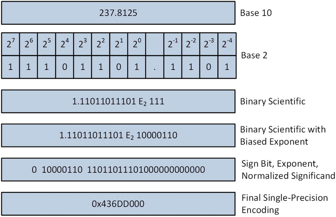
Single-precision floating-point encoding process
Bit Fields for IEEE 754 Compliant Encoding of 237.8125
Sign | Biased Exponent | Normalized Significand |
|---|---|---|
1 | 10000110 | 11011011101000000000000 |
The IEEE 754 floating-point encoding scheme reserves a small set of bit patterns for special values that are used to handle certain processing conditions. The first group of special values includes denormalized numbers (or denormal). As shown in the earlier encoding example, the standard encoding of a floating-point number assumes that the leading digit of the significand is always a 1. One limitation of IEEE 754 floating-point encoding scheme is its inability to accurately represent numbers very close to zero. In these cases, values get encoded using a non-normalized format, which enables tiny numbers close to zero (both positive and negative) to be encoded using less precision. Denormals rarely occur but when they do, the CPU can still process them. In algorithms where the use of a denormal is problematic, a function can test a floating-point value in order to ascertain its denormal state or the processor can be configured to generate an underflow or denormal exception.
Another application of special values involves the encodings that are used for floating-point zero. The IEEE 754 standard supports two different representations of floating-point zero: positive zero (+0.0) and negative zero (–0.0). A negative zero can be generated either algorithmically or as a side effect of the floating-point rounding mode. Computationally, the processor treats positive and negative zero the same and the programmer typically does not need to be concerned.
The IEEE 754 encoding scheme also supports positive and negative representations of infinity. Infinities are produced by certain numerical algorithms, overflow conditions, or division by zero. As discussed later in this chapter, the processor can be configured to generate an exception whenever a floating-point overflow occurs or if a program attempts to divide a number by zero.
The final special value type is called Not a Number (NaN). NaNs are floating-point encodings that represent invalid numbers. The IEEE 754 standard defines two types of NaNs: signaling NaN (SNaN) and quiet NaN (QNaN). SNaNs are created by software; an x86-64 CPU will not create a SNaN during any arithmetic operation. Any attempt by an instruction to use a SNaN will cause an invalid operation exception, unless the exception is masked. SNaNs are useful for testing exception handlers. They can also be exploited by an application program for proprietary numerical-processing purposes. An x86 CPU uses QNaNs as a default response to certain invalid arithmetic operations whose exceptions are masked. For example, one unique encoding of a QNaN, called an indefinite, is substituted for a result whenever a function uses one of the scalar square root instructions with a negative value. QNaNs also can be used by programs to signify algorithm-specific errors or other unusual numerical conditions. When QNaNs are used as operands, they enable continued processing without generating an exception.
When developing software that performs floating-point calculations, it is important to keep in mind that the employed encoding scheme is simply an approximation of a real-number system. It is impossible for any floating-point encoding system to represent an infinite number of values using a finite number of bits. This leads to floating-point rounding errors that can affect the accuracy of a calculation. Also, some mathematical properties that hold true for integers and real numbers are not necessarily true for floating-point numbers. For example, floating-point multiplication is not necessarily associative; (a * b) * c may not equal a * (b * c) depending on the values of a, b, and c. Developers of algorithms that require high levels of floating-point accuracy must be aware of these issues. Appendix A contains a list of references that explain this and other potential pitfalls of floating-point arithmetic in greater detail. Chapter 9 also includes a source code example that exemplifies floating-point non-associativity.
Scalar Floating-Point Register Set

Scalar floating-point values when loaded in an XMM register
Control-Status Register
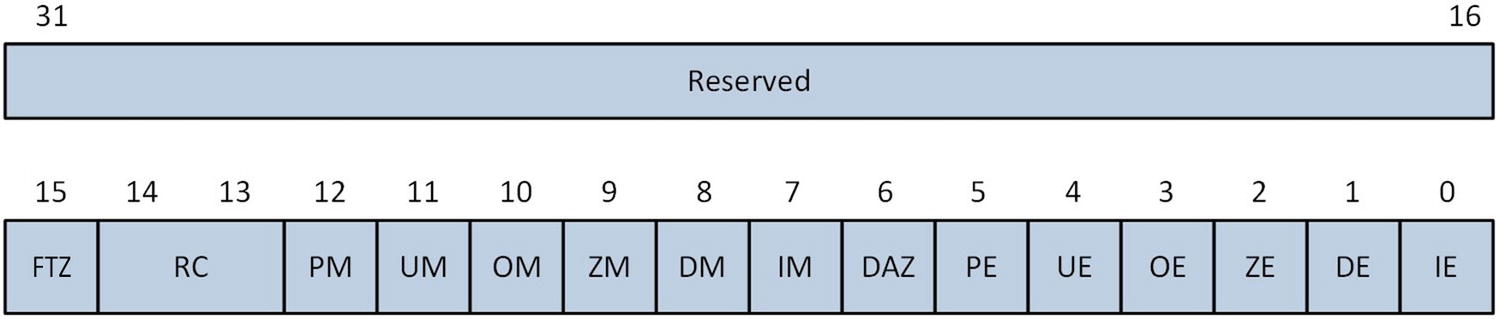
MXCSR control and status register
Description of MXCSR Register Bit Fields
Bit | Field Name | Description |
|---|---|---|
IE | Invalid operation flag | Floating-point invalid operation error flag. |
DE | Denormal flag | Floating-point denormal error flag. |
ZE | Divide-by-zero flag | Floating-point division-by-zero error flag. |
OE | Overflow flag | Floating-point overflow error flag. |
UE | Underflow flag | Floating-point underflow error flag. |
PE | Precision flag | Floating-point precision error flag. |
DAZ | Denormals are zero | When set to 1, forcibly converts a denormal source operand to zero prior to its use in a calculation. |
IM | Invalid operation mask | Floating-point invalid operation error exception mask. |
DM | Denormal mask | Floating-point denormal error exception mask. |
ZM | Divide-by-zero mask | Floating-point divide-by-zero error exception mask. |
OM | Overflow mask | Floating-point overflow error exception mask. |
UM | Underflow mask | Floating-point underflow error exception mask. |
PM | Precision mask | Floating-point precision error exception mask. |
RC | Rounding control | Specifies the method for rounding floating-point results. Valid options include round to nearest (00b), round down toward +∞ (01b), round up toward +∞ (10b), and round toward zero or truncate (11b). |
FTZ | Flush to zero | When set to 1, forces a zero result if the underflow exception is masked and a floating-point underflow error occurs. |
An application program can modify any of the MXCSR’s control flags or status bits to accommodate its specific SIMD floating-point processing requirements. Any attempt to write a non-zero value to a reserved bit position will cause the processor to generate an exception. The processor sets an MXCSR error flag to 1 following the occurrence of an error condition. MXCSR error flags are not automatically cleared by the processor after an error is detected; they must be manually reset. The control flags and status bits of the MXCSR register can be modified using the vldmxcsr (Load MXCSR Register) instruction. Setting a mask bit to 1 disables the corresponding exception. The vstmxcsr (Store MXCSR Register) instruction can be used to save the current MXCSR state. An application program cannot directly access the internal processor tables that specify floating-point exception handlers. However, most C++ compilers provide a library function that allows an application program to designate a callback function that gets invoked whenever a floating-point exception occurs.
The MXCSR includes two control flags that can be used to speed up certain floating-point calculations. Setting the MXCSR.DAZ control flag to 1 can improve the performance of algorithms where the rounding of a denormal value to zero is acceptable. Similarly, the MXCSR.FTZ control flag can be used to accelerate computations where floating-point underflows are common. The downside of enabling either of these options is non-compliance with the IEEE 754 floating-point standard.
Instruction Set Overview
Overview of Commonly-Used AVX Scalar Floating-Point Instructions
Mnemonic | Description |
|---|---|
vadds[d|s] | Scalar floating-point addition |
vbroadcasts[d|s] | Broadcast scalar floating-point value |
vcmps[d|s] | Scalar floating-point compare |
vcomis[d|s] | Ordered scalar floating-point compare and set RFLAGS |
vcvts[d|s]2si | Convert scalar floating-point to doubleword signed integer |
vcvtsd2ss | Convert scalar DPFP to scalar SPFP |
vcvtsi2s[d|s] | Convert signed doubleword integer to scalar floating-point |
vcvtss2sd | Convert scalar SPFP to DPFP |
vcvtts[d|s]2si | Convert with truncation scalar floating-point to signed integer |
vdivs[d|s] | Scalar floating-point division |
vmaxs[d|s] | Scalar floating-point maximum |
vmins[d|s] | Scalar floating-point minimum |
vmovs[d|s] | Move scalar floating-point value |
vmuls[d|s] | Scalar floating-point multiplication |
vrounds[d|s] | Round scalar floating-point value |
vsqrts[d|s] | Scalar floating-point square root |
vsubs[d|s] | Scalar floating-point subtraction |
vucomis[d|s] | Unordered scalar floating-point compare and set RFLAGS |
AVX Scalar Floating-Point Instruction Examples
Instruction | Operation |
|---|---|
vaddss xmm0,xmm1,xmm2 | xmm0[31:0] = xmm1[31:0] + xmm2[31:0] xmm0[127:32] = xmm1[127:32] ymm0[255:128] = 0 |
vaddsd xmm0,xmm1,xmm2 | xmm0[63:0] = xmm1[63:0] + xmm2[63:0] xmm0[127:64] = xmm1[127:64] ymm0[255:128] = 0 |
vsqrtss xmm0,xmm1,xmm2 | xmm0[31:0] = sqrt(xmm2[31:0]) xmm0[127:32] = xmm1[127:32] ymm0[255:128] = 0 |
vsqrtsd xmm0,xmm1,xmm2 | xmm0[63:0] = sqrt(xmm2[63:0]) xmm0[127:64] = xmm1[127:64] ymm0[255:128] = 0 |
AVX Packed Floating-Point
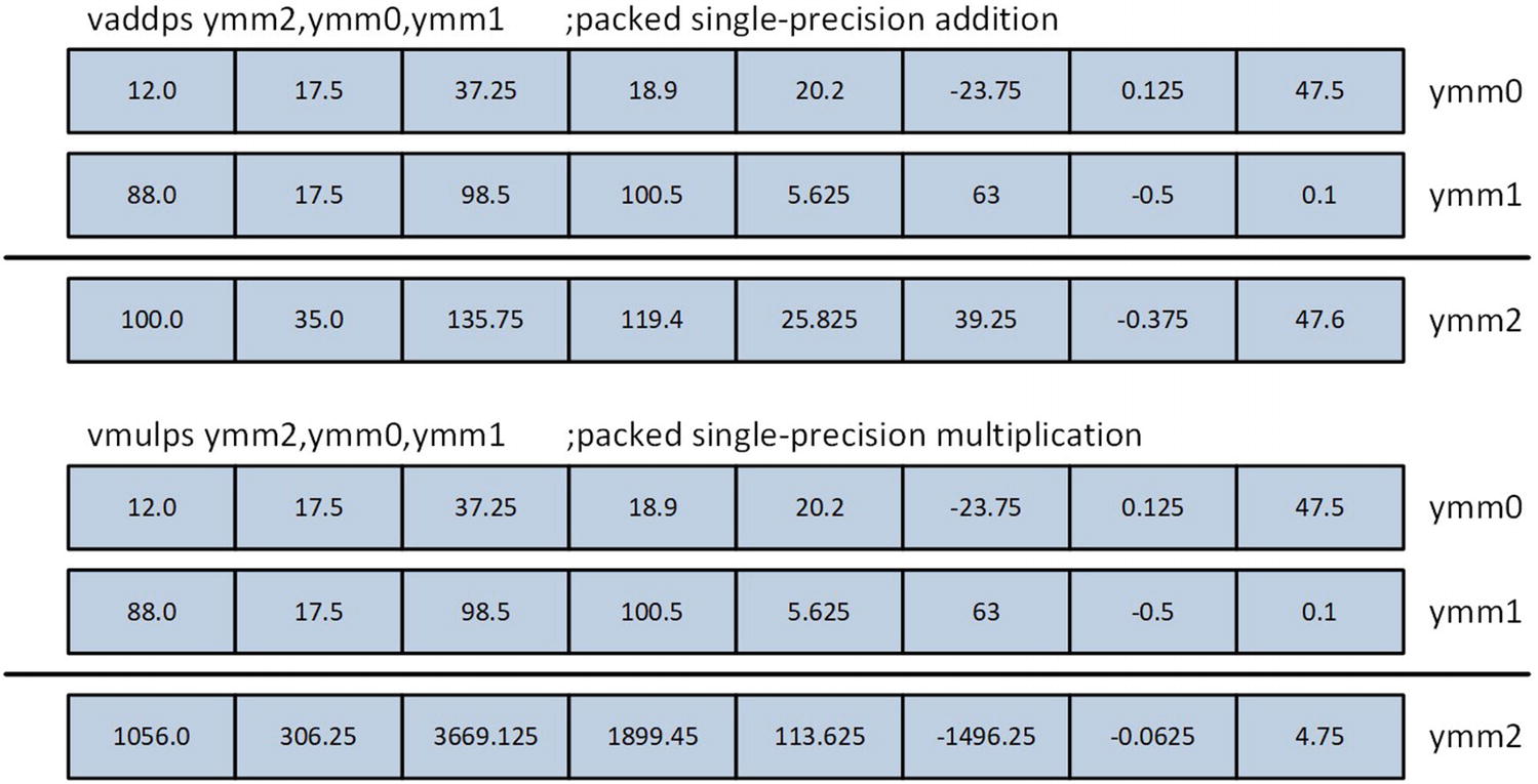
AVX packed single-precision floating-point addition

AVX packed double-precision floating-point multiplication
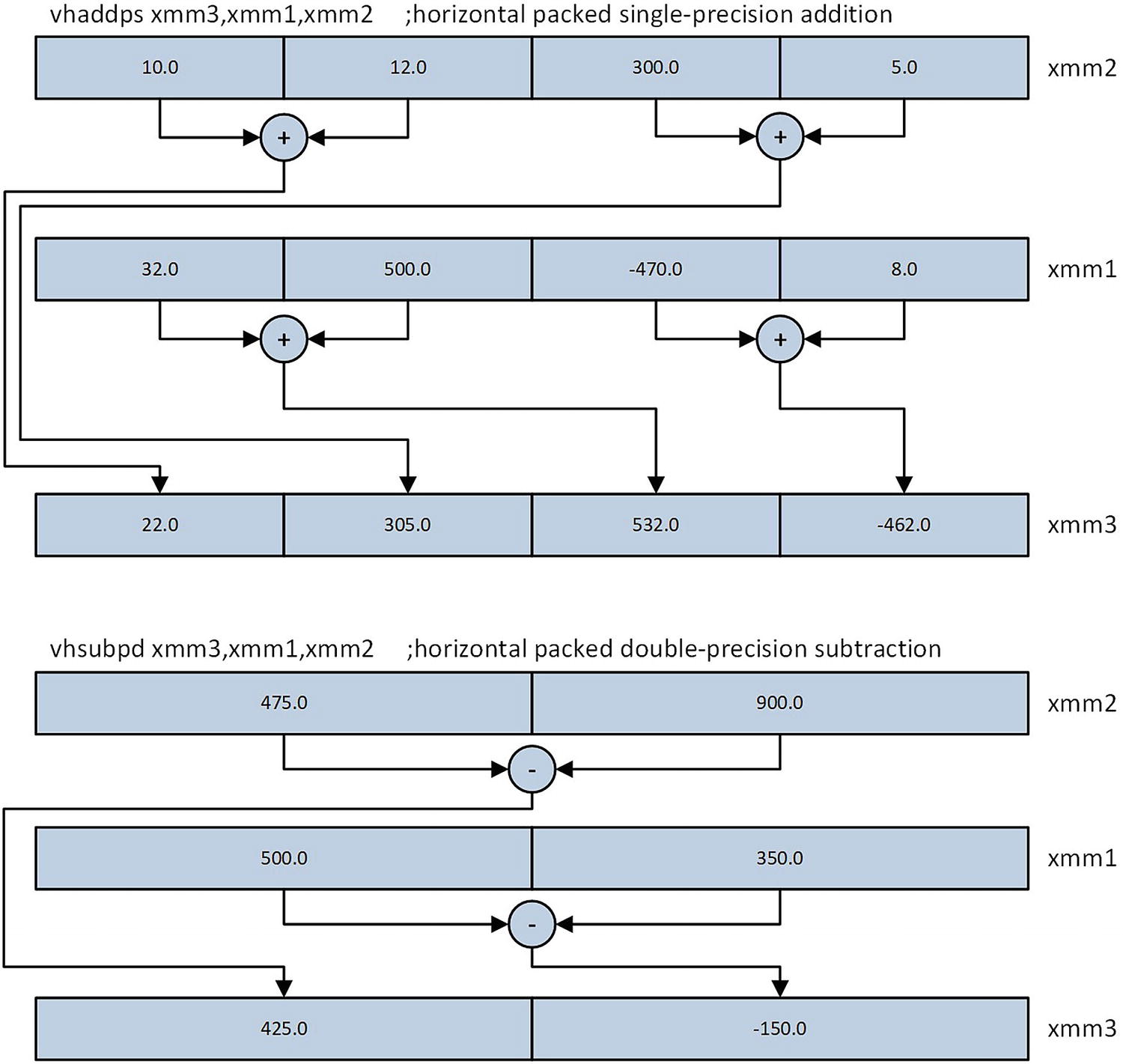
AVX horizontal addition and subtraction using single-precision and double-precision elements
Instruction Set Overview
Overview of Commonly-Used AVX Packed Floating-Point Instructions
Instruction | Description |
|---|---|
vaddp[d|s] | Packed floating-point addition |
vaddsubp[d|s] | Packed floating-point add-subtract |
vandp[d|s] | Packed floating-point bitwise AND |
vandnp[d|s] | Packed floating-point bitwise AND NOT |
vblendp[d|s] | Packed floating-point blend |
vblendvp[d|s] | Variable packed floating-point blend |
vcmpp[d|s] | Packed floating-point compare |
vcvtdq2p[d|s] | Convert packed signed doubleword integers to floating-point |
vcvtp[d|s]2dq | Convert packed floating-point to signed doublewords |
vcvtpd2ps | Convert packed DPFP to packed SPFP |
vcvtps2pd | Convert packed SPFP to packed DPFP |
vdivp[d|s] | Packed floating-point division |
vdpp[d|s] | Packed dot product |
vhaddp[d|s] | Horizontal packed floating-point addition |
vhsubp[d|s] | Horizontal packed floating-point subtraction |
vmaskmovp[d|s] | Packed floating-point conditional load and store |
vmaxp[d|s] | Packed floating-point maximum |
vminp[d|s] | Packed floating-point minimum |
vmovap[d|s] | Move aligned packed floating-point values |
vmovmskp[d|s] | Extract packed floating-point sign bitmask |
vmovup[d|s] | Move unaligned packed floating-point values |
vmulp[d|s] | Packed floating-point multiplication |
vorp[d|s] | Packed floating-point bitwise inclusive OR |
vpermilp[d|s] | Permute in-lane packed floating-point elements |
vroundp[d|s] | Round packed floating-point values |
vshufp[d|s] | Shuffle packed floating-point values |
vsqrtp[d|s] | Packed floating-point square root |
vsubp[d|s] | Packed floating-point subtraction |
vunpckhp[d|s] | Unpack and interleave high packed floating-point values |
vunpcklp[d|s] | Unpack and interleave low packed floating-point values |
vxorp[d|s] | Packed floating-point bitwise exclusive OR |
AVX Packed Integer

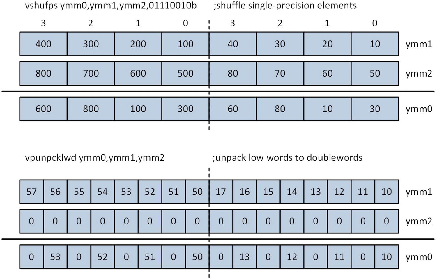
Example AVX packed integer operations
Most AVX packed integer instructions do not update the status flags in the RFLAGS register. This means that error conditions such as arithmetic overflow and underflow are not reported. It also means that the results of a packed integer operation do not directly affect execution of the conditional instructions cmovcc, jcc, and setb. However, programs can employ SIMD-specific techniques to make logical decisions based on the outcome of a packed integer operation. You’ll see examples of these techniques in Chapter 7.
Instruction Set Overview
Overview of Commonly-Used AVX Packed Integer Instructions
Instruction | Description |
|---|---|
vmov[d|q] | Move to/from XMM register |
vmovdqa | Move aligned packed integer values |
vmovdqu | Move unaligned packed integer values |
vpabs[b|w|d] | Packed integer absolute value |
vpackss[dw|wb] | Pack with signed saturation |
vpackus[dw|wb] | Pack with unsigned saturation |
vpadd[b|w|d|q] | Packed integer addition |
vpadds[b|w] | Packed integer addition with signed saturation |
vpaddus[b|w] | Packed integer addition with unsigned saturation |
vpand | Packed bitwise AND |
vpandn | Packed bitwise AND NOT |
vpcmpeq[b|w|d|q] | Pack integer compare for equality |
vpcmpgt[b|w|d|q] | Packed signed integer compare for greater than |
vpextr[b|w|d|q] | Extract integer from XMM register |
vphadd[w|d] | Horizontal packed addition |
vphsub[w|d] | Horizontal packed subtraction |
vpinsr[b|w|d|q] | Insert integer into XMM register |
vpmaxs[b|w|d] | Packed signed integer maximum |
vpmaxu[b|w|d] | Packed unsigned integer maximum |
vpmins[b|w|d] | Packed signed integer minimum |
vpminu[b|w|d] | Packed unsigned integer minimum |
vpmovsx | Packed integer move with sign extend |
vpmovzx | Packed integer move with zero extend |
vpmuldq | Packed signed doubleword multiplication |
vpmulhuw | Packed unsigned word multiplication, save high result |
vpmul[h|l]w | Packed signed word multiplication, save [high | low] result |
vpmull[d|w] | Packed signed multiplication (save low result) |
vpmuludq | Packed unsigned doubleword multiplication |
vpshuf[b|d] | Shuffle packed integers |
vpshuf[h|l]w | Shuffle [high | low] packed words |
vpslldq | Shift logical left double quadword |
vpsll[w|d|q] | Packed logical shift left |
vpsra[w|d] | Packed arithmetic shift right |
vpsrldq | Shift logical right double quadword |
vpsrl[w|d|q] | Packed logical shift right |
vpsub[b|w|d|q] | Packed integer subtraction |
vpsubs[b|w] | Packed integer subtraction with signed saturation |
vpsubus[b|w] | Packed integer subtraction with unsigned saturation |
vpunpckh[bw|wd|dq] | Unpack high data |
vpunpckl[bw|wd|dq] | Unpack low data |
Differences Between x86-AVX and x86-SSE
If you have any previous experience with x86-SSE assembly language programming, you have undoubtedly noticed that a high degree of symmetry exists between this execution environment and x86-AVX. Most x86-SSE instructions have an x86-AVX equivalent that can use either 256-bit or 128-bit wide operands. There are, however, a few important differences between the x86-SSE and x86-AVX execution environments. The remainder of this section explains these differences. Even if you don’t have any previous experience with x86-SSE, I still recommend reading this section since it elucidates important details that you need to be aware of when writing code that uses the x86-AVX instruction set.
Examples of x86-AVX instruction execution using independent lanes
The x86-SSE cvtps2pd instruction converts the two packed single-precision floating-point values in the low-order quadword of XMM1 to double-precision floating-point and saves the result in register XMM0. This instruction does not modify the high-order 128 bits of register YMM0. The first vcvtps2pd instruction performs the same packed single-precision to packed double-precision conversion operation; it also zeros the high-order 128 bits of YMM0. The second vcvtps2pd instruction converts the four packed single-precision floating-point values in the low-order 128 bits of YMM1 to packed double-precision floating-point values and saves the result to YMM0.
X86-AVX relaxes the alignment requirements of x86-SSE for packed operands in memory. Except for instructions that explicitly specify an aligned operand (e.g., vmovaps, vmovdqa, etc.), proper alignment of a 128-bit or 256-bit wide operand in memory is not mandatory. However, 128-bit and 256-bit wide operands should always be properly aligned whenever possible in order to prevent processing delays that can occur when the processor accesses unaligned operands in memory.
The last issue that programmers need to be aware of involves the intermixing of x86-AVX and x86-SSE code. Programs are allowed to intermix x86-AVX and x86-SSE instructions, but any intermixing should be kept to a minimum in order avoid internal processor state transition penalties that can affect performance. These penalties can occur if the processor is required to preserve the upper 128 bits of each YMM register during a transition from executing x86-AVX to executing x86-SSE instructions. State transition penalties can be completely avoided by using the vzeroupper (Zero Upper Bits of YMM Registers) instruction, which zeroes the upper 128 bits of all YMM registers. This instruction should be used prior to any transition from 256-bit x86-AVX code (i.e., any x86-AVX code that uses a YMM register) to x86-SSE code.
One common use of the vzeroupper instruction is by a public function that uses 256-bit x86-AVX instructions. These types of functions should include a vzeroupper instruction prior to the execution of any ret instruction since this prevents processor state transition penalties from occurring in any high-level language code that uses x86-SSE instructions. The vzeroupper instruction should also be employed before calling any library functions that might contain x86-SSE code. Later in this book, you’ll see several source code examples that demonstrate proper use of the vzeroupper instruction. Functions can also use the vzeroall (Zero All YMM Registers) instruction instead of vzeroupper to avoid potential x86-AVX/x86-SSE state transition penalties.
Summary
AVX technology is an x86 platform architectural enhancement that facilitates SIMD operations using 128-bit and 256-bit wide packed floating-point operands, both single-precision and double-precision.
AVX also supports SIMD operations using 128-bit wide packed integer and scalar floating-point operands. AVX2 extends the AVX instruction set to support SIMD operations using 256-bit wide packed integer operands.
AVX adds 16 YMM (256-bit) and XMM (128-bit) registers to the x86-64 platform. Each XMM register is aliased with the low-order 128 bits of its corresponding YMM register.
Most AVX instructions use a three-operand syntax that includes two non-destructive source operands.
AVX floating-point operations conform to the IEEE 754 standard for floating-point arithmetic.
Programs can use the control and status flags in the MXCSR register to enable floating-point exceptions, detect floating-point error conditions, and configure floating-point rounding.
Except for instructions that explicitly specify aligned operands, 128-bit and 256-bit wide operands in memory need not be properly aligned. However, SIMD operands in memory should always be properly aligned whenever possible to avoid delays that can occur when the processor accesses an unaligned operand in memory.
A vzeroupper or vzeroall instruction should be used in any function that uses a YMM register as an operand in order to avoid potential x86-AVX to x86-SSE state transition performance penalties.