
In the preceding chapters, you learned the fundamentals of x86-64 assembly language programming. You also learned how to use the computational recourses of Advanced Vector Extensions to perform SIMD operations. To maximize the performance of your x86 assembly language code, it is often necessary to understand important details about the inner workings of an x86 processor. In this chapter, you’ll explore the internal hardware components of a modern x86 multi-core processor and its underlying microarchitecture. You’ll also learn how to apply specific coding strategies and techniques to boost the performance of your x86-64 assembly language code.
The content of Chapter 15 should be regarded as an introductory tutorial of its topics. A comprehensive examination of x86 microarchitectures and assembly language optimization techniques would minimally require several lengthy chapters, or conceivably an entire book. The primary reference source for this chapter’s material is the Intel 64 and IA-32 Architectures Optimization Reference Manual. You are encouraged to consult this important reference guide for additional information regarding Intel’s x86 microarchitectures and assembly language optimization techniques. The AMD manual Software Optimization Guide for AMD Family 17h Processors also contains useful optimization guidance for x86 assembly language programmers. Appendix A includes additional references that contain more information regarding x86 assembly language optimization strategies and techniques.
Processor Microarchitecture
The performance capabilities of an x86 processor are principally determined by its underlying microarchitecture. A processor’s microarchitecture is characterized by the organization and operation of the following internal hardware components: instruction pipelines, decoders, schedulers, Execution Units, data buses, and caches. Software developers who understand the basics of processor microarchitectures can often glean constructive insights that enable them to develop more efficient code.
This section explains processor microarchitecture concepts using Intel’s Skylake microarchitecture as an illustrative example. The Skylake microarchitecture is utilized in recent mainstream processors from Intel, including sixth generation Core i3, i5, and i7 series CPUs. Seventh (Kaby Lake) and eighth (Coffee Lake) generation Core series CPUs are also based on the Skylake microarchitecture. The structural organization and operation of earlier Intel microarchitectures such as Sandy Bridge and Haswell are comparable to Skylake. Most of the concepts presented in this section are also applicable to microarchitectures developed and used by AMD in its processors, although the underlying hardware implementations vary. Before proceeding it should be noted that the Skylake microarchitecture discussed in this section is similar to but different from the Skylake Server microarchitecture that was referenced in the chapters that described AVX-512 concepts and programming.
Processor Architecture Overview
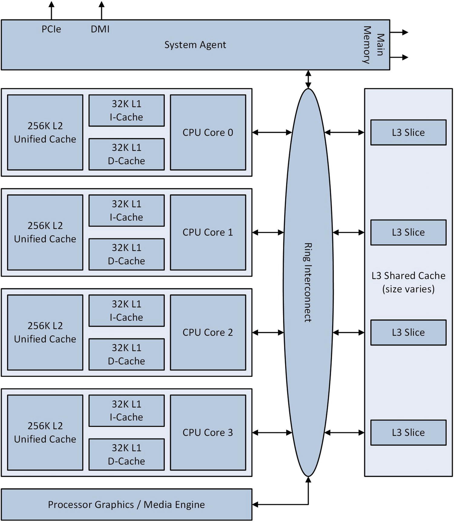
Simplified block diagram of a Skylake-based quad-core processor
If a CPU core requires an instruction or data item that is not present in its L1 or L2 cache, it must be loaded from the L3 cache or main memory. A processor’s L3 cache is partitioned into multiple “slices.” Each slice consists of a logic controller and data array. The logic controller manages access to its corresponding data array. It also handles cache misses and writes to main memory. A cache miss occurs when requested data is not present in the L3 cache and must be loaded from main memory (cache misses also occur when data is not available in the L1 or L2 caches). Each L3 data array includes cache memory, which is organized into 64-byte wide packets called cache lines. The Ring Interconnect is a high-speed internal bus that facilitates data transfers between the CPU cores, L3 cache, graphics unit, and System Agent. The System Agent handles data traffic among the processor, its external data buses, and main memory.
Microarchitecture Pipeline Functionality

Skylake CPU core pipeline functionality
The Instruction Fetch and Pre-Decode Unit grabs instructions from the L1 I-Cache and begins the process of preparing them for execution. Steps performed during this stage include instruction length resolution, decoding of x86 instructional prefixes, and property marking to assist the downstream decoders. The Instruction Fetch and Pre-Decode Unit is also responsible for feeding a constant stream of instructions to the Instruction Queue, which queues up instructions for presentation to the Instruction Decoders.
The Instruction Decoders translate x86 instructions into micro-ops. A micro-op is a self-contained low-level instruction that is ultimately executed by one of the Execution Engine’s Execution Units, which are discussed in the next section. The number of micro-ops generated by the decoders for an x86 instruction varies depending on its complexity. Simple register-register instructions such as add eax,edx and vpxor xmm0,xmm0,xmm0 are decoded into a single micro-op. Instructions that perform more complex operations, such as idiv rcx and vdivsd ymm0,ymm1,ymm2, require multiple micro-ops. The translation of x86 instructions into micro-ops facilitates several architectural and performance benefits, including instruction-level parallelism and out-of-order executions.
The Instruction Decoders also perform two ancillary operations that improve utilization of available pipeline bandwidth. The first of these operations is called micro-fusion, which combines simple micro-ops from the same x86 instruction into a single complex micro-op. Examples of micro-fused instructions include memory stores (mov dword ptr [rbx+16],eax) and calculating instructions that reference operands in memory (sub r9,qword ptr [rbp+48]). Fused complex micro-ops are dispatched by the Execution Engine multiple times (each dispatch executes a simple micro-op from the original instruction). The second ancillary operation carried out by the Instruction Decoders is called macro-fusion. Macro-fusion combines certain commonly-used x86 instruction pairs into a single micro-op. Examples of macro-fusible instruction pairs include many (but not all) conditional jump instructions that are preceded by an add, and, cmp, dec, inc, sub, or test instruction.
Micro-ops from the Instruction Decoders are transferred to the Micro-Op Instruction Queue for eventual dispatch by the Scheduler. They’re also cached, when necessary, in the Decoded Instruction Cache. The Micro-Op Instruction Queue is also used by the Loop Stream Detector, which identifies and locks small program loops in the Micro-Op Instruction Queue. This improves performance since a small loop can repeatedly execute without requiring any additional instruction fetch, decode, and micro-op cache read operations.
The Allocate/Rename block serves as a bridge between the in-order front-end pipelines and the out-of-order Scheduler and Execution Engine. It allocates any needed internal buffers to the micro-ops. It also eliminates false dependencies between micro-ops, which facilitates out-of-order execution. A false dependency occurs when two micro-ops need to simultaneously access distinct versions of the same hardware resource. (In assembly language code, false dependencies can occur when using instructions that update only the low-order 8 or 16 bits of a 32-bit register.) Micro-ops are then transferred to the Scheduler. This unit queues micro-ops until the necessary source operands are available. It then dispatches ready-to-execute micro-ops to the appropriate Execution Unit in the Execution Engine. The Retire Unit removes micro-ops that have completed their execution using the program’s original instruction-ordering pattern. It also signals any processor exceptions that may have occurred during micro-op execution.
Finally, the Branch Prediction Unit helps select the next set of instructions to execute by predicting the branch targets that are most likely to execute based on recent code execution patterns. A branch target is simply the destination operand of a transfer control instruction, such as jcc, jmp, call, or ret. The Branch Prediction Unit enables a CPU core to speculatively execute the micro-ops of an instruction before the outcome of a branch decision is known. When necessary, a CPU core searches (in order) the Decoded Instruction Cache, L1 I-Cache, L2 Unified Cache, L3 Cache, and main memory for instructions to execute.
Execution Engine

Skylake CPU core Execution Engine and its Execution Units
Each Execution Unit performs a specific calculation or operation. For example, the Integer ALU (Arithmetic Logic Unit) Execution Units carry out integer addition, subtraction, and compare operations. The Vector ALU Execution Units handle SIMD integer arithmetic and bitwise Boolean operations. Note that the Execution Engine contains multiple instances of select Execution Units. This allows the Execution Engine to simultaneously execute multiple instances of certain micro-ops in parallel. For example, the Execution Engine can concurrently perform three separate SIMD bitwise Boolean operations in parallel using the Vector ALU Execution Units.
Comparison of Key Buffer Sizes for Recent Intel Microarchitectures
Parameter | Sandy Bridge (2nd Gen) | Haswell (4th Gen) | Skylake (6th Gen) |
|---|---|---|---|
Dispatch ports | 6 | 8 | 8 |
In-flight micro-ops | 168 | 192 | 224 |
In-flight loads | 64 | 72 | 72 |
In-flight stores | 36 | 42 | 56 |
Scheduler entries | 54 | 60 | 97 |
Integer register file | 160 | 168 | 180 |
Floating-point register file | 144 | 168 | 168 |
Optimizing Assembly Language Code
Basic techniques
Floating-point arithmetic
Program branches
Data alignment
SIMD techniques
It is important to keep in mind that the optimization techniques mentioned in this section must be applied in a prudent manner. For example, it makes little sense to add extra push and pop (or other) instructions to a function just to use recommended instruction form only once. Moreover, none of the optimization strategies and techniques described in this section will remedy an inappropriate or poorly designed algorithm. The Intel 64 and IA-32 Architectures Optimization Reference Manual contains additional information regarding the optimization strategies techniques discussed in this section. Appendix A also contains additional references that you can consult for more information regarding optimization of x86 assembly language code.
Basic Techniques
Use a test instruction instead of a cmp instruction when possible, especially to carry out a simple less than, equal to, or greater than zero test.
Avoid using the memory-immediate forms of the cmp and test instructions (e.g., cmp dword ptr [rbp+40],100 or test byte ptr [r12],0fh). Instead, load the memory value into a register and use the register-immediate form of the cmp or test instruction (e.g., mov eax,dword ptr [rbp+40] followed by cmp eax,100).
Minimize use of instructions that perform partial updates of the status flags in RFLAGS. For example, the instructions add eax,1 or sub rax,1 may be faster than inc eax or dec rax, especially in performance-critical loops (the inc and dec instructions do not update RFLAGS.CF) .
Use an xor or sub instruction to zero a register instead of a mov instruction. For example, use an xor eax,eax or sub eax,eax instruction instead of mov eax,0. The mov instruction form can be used when it’s necessary to avoid modifying the status flags in RFLAGS.
Avoid using instructions that require an operand-size prefix to load a 16-bit immediate value since instructions with operand-size prefixes take longer to decode. Use an equivalent 32-bit immediate value instead. For example, use mov edx,42 instead of mov dx,42.
Use 32-bit instead of 64-bit instruction forms and general-purpose registers when possible. For example, if the maximum number of for-loop iterations does not exceed the range limits of a 32-bit integer, use a 32-bit instead of a 64-bit general-purpose register for the loop counter.
Use 32-bit instruction forms to load 64-bit registers with positive constant values. For example, the instructions mov eax,16 and mov r8d,42 effectively set RAX to 16 and R8 to 42.
Use the two- or three-operand form of the imul instruction to multiply two signed integers when the full-width product is not needed. For example, use imul rax,rcx when a 64-bit truncated product is sufficient instead of imul rcx, which returns a 128-bit product in RDX:RAX. This guideline also applies to 32-bit signed integer multiplication.
Avoid declaring data values inside a code section. In situations where it’s necessary to do this (e.g., when defining a read-only jump table), position the data after an unconditional jmp or ret instruction.
In performance-critical processing loops, minimize use of the lea instruction that contains three effective address components (e.g., base register, index register, and displacement). These instructions can only be dispatched to the Slow LEA Execution Unit through Port 1. Shorter forms (one or two effective address components) of the lea instruction can be dispatched via ports 1 or 5 to one of the Fast LEA Execution Units.
Load any memory values that are needed for multiple calculations into a register. If a memory value is needed only for a single calculation, use the register-memory form of the calculating instruction. Table 15-2 shows several examples.
Instruction Form Examples for Single and Multiple-Use Memory Values
Register-Memory Form (Single-Use Data) | Move and Register-Register Form (Multiple-Use Data) |
|---|---|
add edx,dword ptr [x] | mov eax,dword ptr [x] add edx,eax |
and rax,qword ptr [rbx+16] | mov rcx,[rbx+16] and rax,rcx |
cmp ecx,dword ptr [n] | mov eax,dword ptr [n] cmp ecx,eax |
vmulpd xmm0,xmm2,xmmword ptr [rdx] | vmovapd xmm1,xmmword ptr [rdx] vmulpd xmm0,xmm2,xmm1 |
Floating-Point Arithmetic
Always use the computational resources of x86-AVX to perform scalar floating-point arithmetic. Do not use the legacy x87 floating-point unit to perform these types of calculations.
Use single-precision floating-point values instead of double-precision values whenever possible.
Arrange floating-point instruction sequences to minimize register dependencies. Exploit multiple destination registers to save intermediate results, then reduce the intermediate results to a single value (see example Ch11_01).
Partially (or completely) unroll processing loops that contain floating-point calculations, especially loops that contain sequences of floating-point addition, multiplication, or FMA operations.
Avoid arithmetic underflows and denormal values during arithmetic calculations whenever possible.
Avoid using denormalized floating-point constants.
If excessive arithmetic underflows are expected, consider enabling the flush-to-zero (MXCSR.FTZ) and denormals-are-zero (MXCSR.DAZ) modes. See Chapter 4 for more information regarding the proper use of these modes.
Program Branches
Organize code to minimize the number of possible branch instructions.
Partially (or completely) unroll short processing loops to minimize the number of executed conditional jump instructions. Avoid excessive loop unrolling since this may result in slower executing code due to less efficient use of the Loop Stream Detector (see Figure 15-2).
Eliminate unpredictable data-dependent branches using the setcc or cmovcc instructions.
Align branch targets in performance-critical loops to 16-byte boundaries.
Move conditional code that is unlikely to execute (e.g., error-handling code) to another program (or .code) section or memory page.
Use forward conditional jumps when the fall-through code is more likely to execute.
Use backward conditional jumps when the fall-through code is less likely to execute.
Example Ch15_01
Data Alignment
Align multi-byte integer and floating-point values to their natural boundaries.
Align 128-, 256-, and 512-bit wide packed integer and floating-point values to their proper boundaries.
Pad data structures if necessary to ensure proper alignment of each structure member.
Use the appropriate C++ language specifiers and library functions to align data items that are allocated in high-level code. Visual C++ functions can use the alignas(n) specifier or call _aligned_malloc to properly align data items.
Give preference to aligned stores over aligned loads.
Align and position small arrays and short text strings in a data structure to avoid cache line splits. A cache line split occurs when the bytes of a multi-byte value are split across a 64-byte boundary. Positioning small multi-byte values on the same cache line helps minimize the number of memory cycles that the processor must perform.
Evaluate the performance effects of different data layouts such as structure of arrays versus array of structures.
SIMD Techniques
Do not code functions that intermix x86-AVX and x86-SSE instructions. It is okay to code functions that intermix AVX, AVX2, and AVX-512 instructions.
Minimize register dependencies to exploit multiple Execution Units in the Execution Engine.
Load multiple-use memory operands and packed constants into a register.
On systems that support AVX-512, exploit the extra SIMD registers to minimize data dependencies and register spills. A register spill occurs when a function must temporarily save the contents of a register to memory in order to free the register for other calculations.
Use a vpxor, vxorp[d|s], etc. instruction to zero a register instead of a data move instruction. For example, vxorps xmm0,xmm0 is preferred over vmovaps xmm0,xmmword ptr [XmmZero].
Use x86-AVX masking and Boolean operations to minimize or eliminate data-dependent conditional jump instructions.
Perform packed data loads and stores using the aligned move instructions (e.g., vmovdqa, vmovap[d|s], etc.).
Process SIMD arrays using small data blocks to maximize reuse of resident cache data.
Use the vzeroupper instruction when required to avoid x86-AVX to x86-SSE state transition penalties.
Use the doubleword forms of the gather and scatter instructions instead of the quadword forms when possible (e.g., use vgatherdp[d|s] and doubleword indices instead of vgatherqp[d|s] and quadword indices). Perform any required gather operations well ahead of when the data is needed.
Use the non-temporal store instructions (e.g., vmovntdqa, vmovntp[d|s], etc.) to minimize cache pollution.
Use the data prefetch instructions (e.g., prefetcht0, prefetchnta, etc.) to notify the processor of expected-use data items.
Chapter 16 contains a couple of source code examples that illustrate how to use the non-temporal store and data prefetch instructions.
Summary
The performance of most assembly language functions can be improved by implementing the optimization strategies and techniques outlined in this chapter.
The recommended optimization techniques must be judiciously applied. It is not uncommon to encounter coding situations where a recommend strategy or technique is not the best approach.
To achieve optimal performance for a specific algorithm or function, it may be necessary to code multiple versions and compare benchmark timing measurements.
When developing assembly language code, don’t spend an excessive amount of time trying to maximize performance. Focus on performance gains that are relatively easy to attain (e.g., implementing an algorithm using SIMD instead of scalar arithmetic).
None of the optimization strategies and techniques presented in this chapter will ameliorate an inappropriate or poorly designed algorithm.