
Chapter 1 examines the x86-64’s core architecture from the perspective of an application program. It opens with a brief historical overview of the x86 platform in order to provide a frame of reference for subsequent content. This is followed by a review of fundamental, numeric, and SIMD data types. X86-64 core architecture is examined next, which includes explanations of processor register sets, status flags, instruction operands, and memory addressing modes. The chapter concludes with an overview of the core x86-64 instruction set.
Unlike high-level languages such as C and C++, assembly language programming requires the software developer to comprehend specific architectural features of the target processor before attempting to write any code. The topics discussed in this chapter will fulfill this requirement and provide a foundation for understanding the sample code that’s presented later in this book. This chapter also provides the base material that’s necessary to understand the x86-64’s SIMD enhancements.
Historical Overview
Before examining the technical details of the x86-64’s core architecture, it can be beneficial to understand how the architecture has evolved over the years. The short review that follows focuses on noteworthy processors and instruction set enhancements that have affected how software developers use x86 assembly language. Readers who are interested in a more comprehensive chronicle of the x86’s lineage should consult the resources listed in Appendix A.
The x86-64 processor platform is an extension of the original x86-32 platform. The first silicon embodiment of the x86-32 platform was the Intel 80386 microprocessor, which was introduced in 1985. The 80386 extended the architecture of the 16-bit 80286 to include 32-bit wide registers and data types, flat memory model options, a 4 GB logical address space, and paged virtual memory. The 80486 processor improved the performance of the 80386 with the inclusion of on-chip memory caches and optimized instructions. Unlike the 80386 with its separate 80387 floating-point unit (FPU), most versions of the 80486 CPU also included an integrated x87 FPU.
Expansion of the x86-32 platform continued with the introduction of the first Pentium brand processor in 1993. Known as the P5 microarchitecture, performance enhancements included a dual-instruction execution pipeline, 64-bit external data bus, and separate on-chip memory caches for both code and data. Later versions (1997) of the P5 microarchitecture incorporated a new computational resource called MMX technology, which supports single-instruction multiple-data (SIMD) operations on packed integers using 64-bit wide registers. A packed integer is a collection of multiple integer values that are processed simultaneously.
The P6 microarchitecture, first used on the Pentium Pro (1995) and later on the Pentium II (1997), extended the x86-32 platform using a three-way superscalar design. This means that that the processor is able (on average) to decode, dispatch, and execute three distinct instructions during each clock cycle. Other P6 augmentations included out-of-order instruction executions, improved branch prediction algorithms, and speculative executions. The Pentium III, also based on the P6 microarchitecture, was launched in 1999 and included a new SIMD technology called Streaming SIMD extensions (SSE). SSE adds eight 128-bit wide registers to the x86-32 platform and instructions that perform packed single-precision floating-point arithmetic.
In 2000 Intel introduced a new microarchitecture called Netburst that included SSE2, which extended the floating-point capabilities of SSE to cover packed double-precision values. SSE2 also incorporated additional instructions that enabled the 128-bit SSE registers to be used for packed integer calculations and scalar floating-point operations. Processors based on the Netburst architecture included several variations of the Pentium 4. In 2004 the Netburst microarchitecture was upgraded to include SSE3 and hyper-threading technology. SSE3 adds new packed integer and packed floating-point instructions to the x86 platform, while hyper-threading technology parallelizes the processor’s front-end instruction pipelines in order to improve performance. SSE3 capable processors include 90 nm (and smaller) versions of the Pentium 4 and Xeon product lines.
In 2006 Intel launched a new microarchitecture called Core. The Core microarchitecture included redesigns of many Netburst front-end pipelines and execution units in order to improve performance and reduce power consumption. It also incorporated a number of SIMD enhancements including SSSE3 and SSE4.1. These extensions added new packed integer and packed floating-point instructions to the platform but no new registers or data types. Processors based on the Core microarchitecture include CPUs from the Core 2 Duo and Core 2 Quad series and Xeon 3000/5000 series.
A microarchitecture called Nehalem followed Core in late 2008. This microarchitecture re-introduced hyper-threading to the x86 platform, which had been excluded from the Core microarchitecture. The Nehalem microarchitecture also incorporates SSE4.2. This final x86-SSE enhancement adds several application-specific accelerator instructions to the x86-SSE instruction set. SSE4.2 also includes new instructions that facilitate text string processing using the 128-bit wide x86-SSE registers. Processors based on the Nehalem microarchitecture include first generation Core i3, i5, and i7 CPUs. It also includes CPUs from the Xeon 3000, 5000, and 7000 series.
In 2011 Intel launched a new microarchitecture called Sandy Bridge. The Sandy Bridge microarchitecture introduced a new x86 SIMD technology called Advanced Vector Extensions (AVX). AVX adds packed floating-point operations (both single-precision and double-precision) using 256-bit wide registers. AVX also supports a new three-operand instruction syntax, which improves code efficiency by reducing the number of register-to-register data transfers that a software function must perform. Processors based on the Sandy Bridge microarchitecture include second and third generation Core i3, i5, and i7 CPUs along with Xeon V2 series CPUs.
In 2013 Intel unveiled its Haswell microarchitecture. Haswell includes AVX2, which extends AVX to support packed-integer operations using 256-bit wide registers. AVX2 also supports enhanced data transfer capabilities with its broadcast, gather, and permute instructions. (Broadcast instructions replicate a single value to multiple locations; data gather instructions load multiple elements from non-contiguous memory locations; permute instructions rearrange the elements of a packed operand.) Another feature of the Haswell microarchitecture is its inclusion of fused-multiply-add (FMA) operations. FMA enables software algorithms to perform product-sum (or dot product) calculations using a single floating-point rounding operation, which can improve both performance and accuracy. The Haswell microarchitecture also encompasses several new general-purpose register instructions. Processors based on the Haswell microarchitecture include fourth generation Core i3, i5, and i7 CPUs. AVX2 is also included later generations of Core family CPUs, and in Xeon V3, V4, and V5 series CPUs.
X86 platform extensions over the past several years have not been limited to SIMD enhancements. In 2003 AMD introduced its Opteron processor, which extended the x86’s execution platform from 32 bits to 64 bits. Intel followed suit in 2004 by adding essentially the same 64-bit extensions to its processors starting with certain versions of the Pentium 4. All Intel processors based on the Core, Nehalem, Sandy Bridge, Haswell, and Skylake microarchitectures support the x86-64 execution environment.
Processors from AMD have also evolved over the past few years. In 2003 AMD introduced a series of processors based on its K8 microarchitecture. Original versions of the K8 included support for MMX, SSE, and SSE2 while later versions added SSE3. In 2007 the K10 microarchitecture was launched and included a SIMD enhancement called SSE4a. SSE4a contains several mask shift and streaming store instructions that are not available on processors from Intel. Following the K10, AMD introduced a new microarchitecture called Bulldozer in 2011. The Bulldozer microarchitecture includes SSSE3, SSE4.1, SSE4.2, SSE4a, and AVX. It also includes FMA4, which is a four-operand version of fused-multiply-add. Like SSE4a, processors marketed by Intel do not support FMA4 instructions. A 2012 update to the Bulldozer microarchitecture called Piledriver includes support for both FMA4 and the three-operand version of FMA, which is called FMA3 by some CPU feature-detection utilities and third-party documentation sources. The most recent AMD microarchitecture, introduced during 2017, is called Zen. This microarchitecture includes the AVX2 instruction set enhancements and is used in the Ryzen series of processors.
High-end desktop and server-oriented processors based on Intel’s Skylake-X microarchitecture, also first marketed during 2017, include a new SIMD extension called AVX-512. This architectural enhancement supports packed integer and floating-point operations using 512-bit wide registers. AVX-512 also includes architectural additions that facilitate instruction-level conditional data merging, floating-point rounding control, and broadcast operations. Over the next few years, it is expected that both AMD and Intel will incorporate AVX-512 into their mainstream processors for desktop and notebook PCs.
Data Types
Programs written using x86 assembly language can use a wide variety of data types. Most program data types originate from a small set of fundamental data types that are intrinsic to the x86 platform. These fundamental data types enable the processor to perform numerical and logical operations using signed and unsigned integers, single-precision (32-bit) and double-precision (64-bit) floating-point values, text strings, and SIMD values. In this section, you’ll learn about the fundamental data types along with a few miscellaneous data types supported by the x86.
Fundamental Data Types
Fundamental Data Types
Data Type | Size (Bits) | Typical Use |
|---|---|---|
Byte | 8 | Characters, small integers |
Word | 16 | Characters, integers |
Doubleword | 32 | Integers, single-precision floating-point |
Quadword | 64 | Integers, double-precision floating-point |
Double Quadword | 128 | Packed integers, packed floating-point |

Bit-numbering and byte-ordering for fundamental data types
A properly-aligned fundamental data type is one whose address is evenly divisible by its size in bytes. For example, a doubleword is properly aligned when it’s stored at a memory location with an address that is evenly divisible by four. Similarly, quadwords are properly aligned at addresses evenly divisible by eight. Unless specifically enabled by the operating system, an x86 processor does not require proper alignment of multi-byte fundamental data types in memory. However, it is standard practice to properly align all multi-byte values whenever possible in order to avoid potential performance penalties that can occur if the processor is required to access misaligned data in memory.
Numerical Data Types
X86 Numerical Data Types
Type | Size (Bits) | C/C++ Type | <cstdint> |
|---|---|---|---|
Signed integers | 8 | char | int8_t |
16 | short | int16_t | |
32 | int, long | int32_t | |
64 | long long | int64_t | |
Unsigned integers | 8 | unsigned char | uint8_t |
16 | unsigned short | uint16_t | |
32 | unsigned int, unsigned long | uint32_t | |
64 | unsigned long long | uint64_t | |
Floating-point | 32 | float | Not applicable |
64 | double | Not applicable |
SIMD Data Types
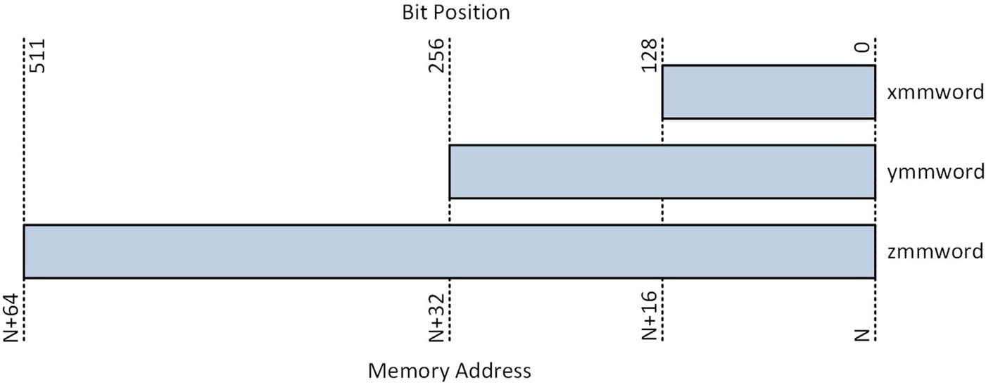
SIMD data types
SIMD Data Types and Maximum Number of Data Elements
Numerical Type | xmmword | ymmword | zmmword |
|---|---|---|---|
8-bit integer | 16 | 32 | 64 |
16-bit integer | 8 | 16 | 32 |
32-bit integer | 4 | 8 | 16 |
64-bit integer | 2 | 4 | 8 |
Single-precision floating-point | 4 | 8 | 16 |
Double-precision floating-point | 2 | 4 | 8 |
As discussed earlier in this chapter, SIMD enhancements have been regularly added to the x86 platform starting in 1997 with MMX technology and most recently with the addition of AVX-512. This presents some challenges to the software developer who wants to exploit these technologies in that the packed data types described in Table 1-3 and their associated instruction sets are not universally supported by all processors. Fortunately, methods are available to determine at runtime the specific SIMD features and instruction sets that a processor supports. You’ll learn how to use some of these methods in Chapter 16.
Miscellaneous Data Types
The x86 platform also supports a number of miscellaneous data types including strings, bit fields, and bit strings. An x86 string is contiguous block of bytes, words, doublewords, or quadwords. X86 strings are used to support text-based data types and processing operations. For example, the C/C++ data types char and wchar_t are usually implemented using an x86 byte or word, respectively. X86 strings can also be employed to perform processing operations on arrays, bitmaps, and similar contiguous-block data structures. The x86 instruction set includes instructions that can carry out compare, load, move, scan, and store operations using strings.
Other miscellaneous data types include bit fields and bit strings. A bit field is a contiguous sequence of bits and is used as a mask value by some instructions. A bit field can start at any bit position within a byte and contain up to 32 bits. A bit string is a contiguous sequence of bits containing up to 232 – 1 bits. The x86 instruction set includes instructions that can clear, set, scan, and test individual bits within a bit string.
Internal Architecture
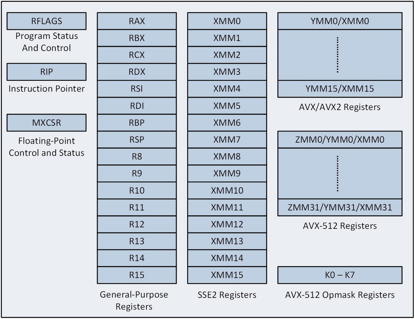
X86-64 processor internal architecture
All x86-64 compatible processors support SSE2 and include 16 128-bit XMM registers that programmers can use to perform scalar floating-point computations. These registers can also be employed to carry out SIMD operations using packed integers or packed floating-point values (both single precision and double precision). You’ll learn how to use the XMM registers, the MXCSR register, and the AVX instruction set to perform floating-point calculations in Chapter 4 and 5. This chapter also discusses the YMM register set and other AVX architectural concepts in greater detail. You’ll learn about AVX2 and AVX-512 in Chapters 8 and 12, respectively.
General-Purpose Registers

X86-64 general-purpose registers
The low-order doubleword, word, and byte of each 64-bit register are independently accessible and can be used to manipulate 32-bit, 16-bit, and 8-bit wide operands. For example, a function can use registers EAX, EBX, ECX, and EDX to perform 32-bit calculations in the low-order doublewords of registers RAX, RBX, RCX, and RDX, respectively. Similarly, registers AL, BL, CL, and DL can be used to carry out 8-bit calculations in the low-order bytes. It should be noted that a discrepancy exists regarding the names of some byte registers. The Microsoft 64-bit assembler uses the names shown in Figure 1-4, while the Intel documentation uses the names R8L – R15L. This book uses the Microsoft register names in order to maintain consistency between the text and the sample code. Not shown in Figure 1-4 are the legacy byte registers AH, BH, CH, and DH. These registers are aliased to the high-order bytes of registers AX, BX, CX, and DX, respectively. The legacy byte registers can be used in x86-64 programs, albeit with some restrictions, as described later in this chapter.
Despite their designation as general-purpose registers, the x86-64 instruction set imposes some notable restrictions on how they can be used. Some instructions either require or implicitly use specific registers as operands. This is a legacy design pattern that dates back to the 8086 ostensibly to improve code density. For example, some variations of the imul (Signed Integer Multiplication) instruction save the calculated integer product to RDX:RAX, EDX:EAX, DX:AX, or AX (the colon notation signifies that the final product is contained in two registers, with the first register holding the high-order bits). The idiv (Signed Integer Division) instruction requires the integer dividend to be loaded in RDX:RAX, EDX:EAX, DX:AX, or AX. The x86 string instructions require that the addresses of the source and destination operands be placed in registers RSI and RDI, respectively. String instructions that include a repeat prefix must use RCX as the count register, while variable-bit shift and rotate instructions must load the count value into register CL.
The processor uses register RSP to support stack-related operations such as function calls and returns. The stack itself is simply a contiguous block of memory that is assigned to a process or thread by the operating system. Application programs can also use the stack to pass function arguments and store temporary data. The RSP register always points to the stack's top most item. Stack push and pop operations are performed using 64-bit wide operands. This means that the location of the stack in memory is usually aligned to an 8-byte boundary. Some runtime environments (e.g., 64-bit Visual C++ programs running on Windows) align stack memory and RSP to a 16-byte boundary in order to avoid improperly-aligned memory transfers between the XMM registers and 128-bit wide operands stored on the stack.
While it is technically possible to use the RSP register as a general-purpose register, such use is impractical and strongly discouraged. Register RBP is typically used as a base pointer to access data items that are stored on the stack. RSP can also be used as a base pointer to access data items on the stack. When not employed as a base pointer, programs can use RBP as a general-purpose register.
RFLAGS Register
RFLAGS Register
Bit Position | Name | Symbol | Use |
|---|---|---|---|
0 | Carry Flag | CF | Status |
1 | Reserved | 1 | |
2 | Parity Flag | PF | Status |
3 | Reserved | 0 | |
4 | Auxiliary Carry Flag | AF | Status |
5 | Reserved | 0 | |
6 | Zero Flag | ZF | Status |
7 | Sign Flag | SF | Status |
8 | Trap Flag | TF | System |
9 | Interrupt Enable Flag | IF | System |
10 | Direction Flag | DF | Control |
11 | Overflow Flag | OF | Status |
12 | I/O Privilege Level Bit 0 | IOPL | System |
13 | I/O Privilege Level Bit 1 | IOPL | System |
14 | Nested Task | NT | System |
15 | Reserved | 0 | |
16 | Resume Flag | RF | System |
17 | Virtual 8086 Mode | VM | System |
18 | Alignment Check | AC | System |
19 | Virtual Interrupt Flag | VIF | System |
20 | Virtual Interrupt Pending | VIP | System |
21 | ID Flag | ID | System |
22 - 63 | Reserved | 0 |
For application programs, the most important bits in the RFLAGS register are the following status flags: carry flag (CF), overflow flag (OF), parity flag (PF) , sign flag (SF) , and zero flag (ZF). The carry flag is set by the processor to signify an overflow condition when performing unsigned integer arithmetic. It is also used by some register rotate and shift instructions. The overflow flag signals that the result of a signed integer operation is too small or too large. The processor sets the parity flag to indicate whether the least-significant byte of an arithmetic, compare, or logical operation contains an even number of 1 bits (parity bits are used by some communication protocols to detect transmission errors). The sign and zero flags are set by arithmetic and logical instructions to signify a negative, zero, or positive result.
The RFLAGS register contains control bit called the direction flag (DF). An application program can set or reset the direction flag, which defines the auto increment direction (0 = low to high addresses, 1 = high to low addresses) of the RDI and RSI registers during execution of string instructions. The remaining bits in the RFLAGS register are used exclusively by the operating system to manage interrupts, restrict I/O operations, support program debugging, and handle virtual operations. They should never be modified by an application program. Reserved bits also should never be modified, and no assumptions should ever be made regarding the state of any reserved bit.
Instruction Pointer
The instruction pointer register (RIP) contains the logical address of the next instruction to be executed. The value in register RIP updates automatically during execution of each instruction. It is also implicitly altered during execution of control-transfer instructions. For example, the call (Call Procedure) instruction pushes the contents of the RIP register onto the stack and transfers program control to the address designated by the specified operand. The ret (Return from Procedure) instruction transfers program control by popping the top-most eight bytes off the stack and loading them into the RIP register.
The jmp (Jump) and jcc (Jump if Condition is Met) instructions also transfer program control by modifying the contents of the RIP register. Unlike the call and ret instructions, all x86-64 jump instructions are executed independent of the stack. The RIP register is also used for displacement-based operand memory addressing as explained in the next section. It is not possible for an executing task to directly access the contents of the RIP register.
Instruction Operands
All x86-64 instructions use operands, which designate the specific values that an instruction will act upon. Nearly all instructions require one or more source operands along with a single destination operand. Most instructions also require the programmer to explicitly specify the source and destination operands. There are, however, a number of instructions where the register operands are either implicitly specified or required by an instruction, as discussed in the previous section.
Examples of Basic Operand Types
Type | Example | Analogous C/C++ Statement |
|---|---|---|
Immediate | mov rax,42 | rax = 42 |
imul r12,-47 | r12 *= -47 | |
shl r15,8 | r15 <<= 8 | |
xor ecx,80000000h | ecx ^= 0x80000000 | |
sub r9b,14 | r9b -= 14 | |
Register | mov rax,rbx | rax = rbx |
add rbx,r10 | rbx += r10 | |
mul rbx | rdx:rax = rax * rbx | |
and r8w,0ff00h | r8w &= 0xff00 | |
Memory | mov rax,[r13] | rax = *r13 |
or rcx,[rbx+rsi*8] | rcx |= *(rbx+rsi*8) | |
sub qword ptr [r8],17 | *(long long*)r8 -= 17 | |
shl word ptr [r12],2 | *(short*)r12 <<= 2 |
The mul rbx (Unsigned Multiply) instruction that is shown in Table 1-5 is an example of implicit operand usage. In this example, implicit register RAX and explicit register RBX are used as the source operands, and implicit register pair RDX:RAX is the destination operand. The multiplicative product’s high-order and low-order quadwords are stored in RDX and RAX, respectively.
In Table 1-5’s penultimate example, the text qword ptr is an assembler operator that acts like a C/C++ cast operator. In this instance, the value 17 is subtracted from a 64-bit value whose memory location is specified by the contents of register R8. Without the qword ptr operator, the assembly language statement is ambiguous since the assembler can't ascertain the size of the operand pointed to by R8. In this example, the destination could also an 8-bit, 16-bit, or 32-bit sized operand. The final example in Table 1-5 uses the word ptr operator in a similar manner. You’ll learn more about assembler operators and directives in the programming chapters of this book.
Memory Addressing
Memory Operand Addressing
Addressing Form | Example |
|---|---|
RIP + Disp | mov rax,[Val] |
BaseReg | mov rax,[rbx] |
BaseReg + Disp | mov rax,[rbx+16] |
IndexReg * SF + Disp | mov rax,[r15*8+48] |
BaseReg + IndexReg | mov rax,[rbx+r15] |
BaseReg + IndexReg + Disp | mov rax,[rbx+r15+32] |
BaseReg + IndexReg * SF | mov rax,[rbx+r15*8] |
BaseReg + IndexReg * SF + Disp | mov rax,[rbx+r15*8+64] |
The memory addressing forms shown in Table 1-6 are used to directly reference program variables and data structures. For example, the simple displacement form is often used to access a simple global or static variable. The base register form is analogous to a C/C++ pointer and is used to indirectly reference a single value. Individual fields within a data structure can be retrieved using a base register and a displacement. The index register forms are useful for accessing individual elements within an array. Scale factors can reduce the amount code needed to access the elements of an array that contains integer or floating-point values. Elements in more elaborate data structures can be referenced by using a base register together with an index register, scale factor, and displacement.

RIP-relative effective address calculation
One minor constraint of RIP-relative addressing is that the target operand must reside with a ± 2 GB address window of the value that’s contained in register RIP. For most programs, this limitation is rarely a concern. The calculation of a RIP-relative displacement value is automatically determined by the assembler during code generation. This means that you can use a mov rax,[Val] or similar instructions without having to worry about the details of the displacement value calculation.
Differences Between x86-64 and x86-32 Programming
There are some important differences between x86-64 and x86-32 assembly language programming. If you are learning x86 assembly language programming for the first time, you can either skim or skip this section since it discusses concepts that aren’t fully explained until later in this book.
Most existing x86-32 instructions have an x86-64 equivalent instruction that enables a function to exploit 64-bit wide addresses and operands. X86-64 functions can also perform calculations using instructions that manipulate 8-bit, 16-bit, or 32-bit registers and operands. Except for the mov instruction, the maximum size of an x86-64 mode immediate value is 32 bits. If an instruction manipulates a 64-bit wide register or memory operand, any specified 32-bit immediate value is signed-extended to 64 bits prior to its use.
Examples of x86-64 Instructions Using Various Operand Sizes
8-Bit | 16-Bit | 32-Bit | 64-Bit |
|---|---|---|---|
add al,bl | add ax,bx | add eax,ebx | add rax,rbx |
cmp dl,[r15] | cmp dx,[r15] | cmp edx,[r15] | cmp rdx,[r15] |
mul r10b | mul r10w | mul r10d | mul r10 |
or [r8+rdi],al | or [r8+rdi],ax | or [r8+rdi],eax | or [r8+rdi],rax |
shl r9b,cl | shl r9w,cl | shl r9d,cl | shl r9,cl |

Using 64-bit registers with immediate operands
The third example employs a mov rdx,0ffh instruction to initialize register RDX. This is followed by an or rdx,80000000h instruction that sign extends the immediate value 0x80000000 to 0xFFFFFFFF80000000, and then performs a bitwise inclusive OR operation. The value that's shown for RDX is almost certainly not the intended result. The final example illustrates how to carry out an operation that requires a 64-bit immediate value. A mov r8,80000000h instruction loads the 64-bit value 0x0000000080000000 into R8. As mentioned earlier in this section, the mov instruction is the only instruction that supports 64-bit immediate operands. Execution of the ensuing or rdx,r8 instruction yields the expected value.
The 32-bit size limitation for immediate values also applies to jmp and call instructions that specify relative-displacement targets. In these cases, the target (or location) of a jmp or call instruction must reside with a ± 2 GB address window of the current RIP register. Targets whose relative displacements exceed this window can only be accessed using a jmp or call instruction that employs an indirect operand (e.g., jmp qword ptr [FuncPtr] or call rax). Like RIP-relative addressing, the size limitations described in this paragraph are unlikely to present significant obstacles for most assembly language functions.
Another difference between x86-32 and x86-64 assembly language programming is the effect that some instructions have on the upper 32 bits of a 64-bit general-purpose register. When using instructions that manipulate 32-bit registers and operands, the high-order 32 bits of the corresponding 64-bit general-purpose register are zeroed during execution. For example, assume that register RAX contains the value 0x8000000000000000. Execution of the instruction add eax,10 generates a result of 0x000000000000000A in RAX. However, when working with 8-bit or 16-bit registers and operands, the upper 56 or 48 bits of the corresponding 64-bit general-purpose register are not modified. Assuming again that if RAX contains 0x8000000000000000, execution of the instructions add al,20 or add ax,40 would yield RAX values of 0x8000000000000014 or 0x8000000000000028, respectively.
The x86-64 platform imposes some restrictions on the use of legacy registers AH, BH, CH, and DH. These registers cannot be used with instructions that also reference one of the new 8-bit registers (i.e., SIL, DIL, BPL, SPL, and R8B - 15B). Existing x86-32 instructions such as mov ah,bl and add dh,bl are still allowed in x86-64 programs. However, the instructions mov ah,r8b and add dh,r8b are invalid.
Invalid Instructions
X86-64 Mode Invalid Instructions
Mnemonic | Name |
|---|---|
aaa | ASCII Adjust After Addition |
aad | ASCII Adjust After Division |
aam | ASCII Adjust After Multiplication |
aas | ASCII Adjust After Subtraction |
bound | Check Array Index Against Bounds |
daa | Decimal Adjust After Addition |
das | Decimal Adjust After Subtraction |
into | Generate interrupt if RFLAGS.OF Equals 1 |
pop[a|ad] | Pop all General-Purpose Registers |
push[a|ad] | Push all General-Purpose Registers |
Deprecated Instructions
Processors that support the x86-64 instruction set also include the computational resources of SSE2. This means that x86-64 programs can safely use the packed integer instructions of SSE2 instead of MMX. It also means that x86-64 programs can use SSE2’s (or AVX’s if available) scalar floating-point instructions instead of x87 FPU instructions. X86-64 programs can still take advantage of the MMX and x87 FPU instruction sets, and such use might be warranted when migrating x86-32 legacy code to the x64-64 platform. For new x86-64 software development, however, using the MMX and x87 FPU instruction sets is not recommended.
Instruction Set Overview
Table 1-9 lists in alphabetical order the core x86-64 instructions that are frequently used in assembly language functions. For each instruction mnemonic, there is a deliberately succinct description since comprehensive details of each instruction including execution particulars, valid operands, affected flags, and exceptions are readily available in reference manuals published by AMD and Intel. Appendix A contains a list of these manuals. The programming examples in Chapters 2 and 3 also contain additional information regarding proper use of these instructions.
Overview of Core X86-64 Instructions
Mnemonic | Instruction Name |
|---|---|
adc | Integer addition with carry |
add | Integer addition |
and | Bitwise AND |
bs[f|r] | Bit scan forward, bit scan reverse |
b[t|tr|ts] | Bit test; Bit test and reset; Bit test and set |
call | Call procedure |
cld | Clear direction flag (RFLAGS.DF) |
cmovcc | Conditional move |
cmp | Compare operands |
cmps[b|w|d|q] | Compare string operands |
cupid | Query CPU identification and feature information |
c[wd|dq|do] | Convert operand |
dec | Decrement operand by 1 |
div | Unsigned integer division |
idiv | Signed integer division |
imul | Signed integer multiplication |
inc | Increment operand by 1 |
jcc | Conditional jump |
jmp | Unconditional jump |
lahf | Load status flags into register AH |
lea | Load effective address |
lods[b|w|d|q] | Load string operand |
mov | Move data |
mov[sx|sxd] | Move integer with sign extension |
movzx | Move integer with zero extension |
mul | Unsigned integer multiplication |
neg | Two’s complement negation |
not | One’s complement negation |
or | Bitwise inclusive OR |
pop | Pop top-of-stack value to operand |
popfq | Pop top-of-stack value to RFLAGS |
push | Push operand onto stack |
pushfq | Push RFLAGS onto stack |
rc[l|r] | Rotate left with RFLAGS.CF; Rotate right with RFLAGS.CF |
ret | Return from procedure |
re[p|pe|pz|pne|pnz] | Repeat string operation (instruction prefix) |
ro[l|r] | Rotate left; Rotate right |
sahf | Store AH into status flags |
sar | Shift arithmetic right |
setcc | Set byte on condition |
sh[l|r] | Shift logical left; Shift logical right |
sbb | Integer subtraction with borrow |
std | Set direction flag (RFLAGS.DF) |
stos[b|w|d|q] | Store string value |
test | Test operand (sets status flags) |
xchg | Exchange source and destination operand values |
xor | Bitwise exclusive OR |
Condition Codes, Mnemonic Suffixes, and Test Conditions
Condition Code | Mnemonic Suffix | RFLAGS Test Condition |
|---|---|---|
Above Neither below nor equal | A NBE | CF == 0 && ZF == 0 |
Above or equal Not below | AE NB | CF == 0 |
Below Neither above nor equal | B NAE | CF == 1 |
Below or equal Not above | BE NA | CF == 1 || ZF == 1 |
Equal Zero | E Z | ZF == 1 |
Not equal Not zero | NE NZ | ZF == 0 |
Greater Neither less nor equal | G NLE | ZF == 0 && SF == OF |
Greater or equal Not less | GE NL | SF == OF |
Less Neither greater nor equal | L NGE | SF != OF |
Less or equal Not greater | LE NG | ZF == 1 || SF != OF |
Sign | S | SF == 1 |
Not sign | NS | SF == 0 |
Carry | C | CF == 1 |
Not carry | NC | CF == 0 |
Overflow | O | OF == 1 |
Not overflow | NO | OF == 0 |
Parity Parity even | P PE | PF == 1 |
Not parity Parity odd | NP PO | PF == 0 |
The alternate forms of many Table 1-10 mnemonics are defined to provide algorithmic flexibility or improve program readability. When using one of the aforementioned conditional instructions in source code, condition-codes containing the words “above” and “below” are employed for unsigned-integer operands while the words “greater” and “less” are used for signed-integer operands. If the contents of Table 1-10 seem a little confusing or abstract, don’t worry. You'll see a plethora of condition code examples in subsequent chapters of this book.
Summary
The fundamental data types of the x86-64 platform include bytes, words, doublewords, quadwords, and double quadwords. Intrinsic programming language data types such as characters, text strings, integers, and floating-point values are derived from the fundamental data types.
The x86-64 execution unit includes 16 64-bit general-purpose registers that are used to perform arithmetic, logical, and data transfer operations using 8-bit, 16-bit, 32-bit and 64-bit operands.
The x86-64 execution unit includes 16 128-bit XMM registers that can be used to perform scalar floating-point arithmetic using single-precision or double-precision values. These registers can also be employed to carry out SIMD operations using packed integers or packed floating-point values.
Most x86-64 assembly language instructions can be used with the following explicit operand types: immediate, register, and memory. Some instructions employ implicit registers as their operands.
An operand in memory can be referenced using a variety of addressing modes that include one or more of the following components: fixed displacement, base register, index register, and/or scale factor.
Most arithmetic and logical instructions update one or more of the status flags in the RFLAGS register. These flags can be tested to alter program flow or conditionally assign values to variables.