
This chapter deals with the practical issues of setting up a network and network architecture in general. Knowing how networks differ from a programmatic perspective can help fix a lot of network-application-related bugs. Furthermore, basic working knowledge of network setup is essential in the day-to-day life of many developers.
This chapter is structured in two sections. The first section explains how to create a network from autonomous, stand-alone machines. Immediately following that is a discussion of common devices that form gateways between your network and the Internet. These gateway devices can often create problems for your software by imposing their own restrictions and regulations. By being able to detect and work around these problems, your application will be more stable in a mass-market environment.
If you are developing a point-of-sale system for a supermarket, each terminal will need to communicate with a central server to consolidate the day’s takings and process stock levels. This is not easily achievable without a network. In many cases, you can’t just give a shopkeeper a CD and expect him to figure out how to get every computer in his business tied to a single network.
If you have only two computers that you want to network, and there is no need for a third, then the most economic solution is a unshielded twisted pair (UTP) crossover cable (not UTP patch cable). This can be used to link two computers directly.
There are three main types of physical connections in modern networking: UTP, BNC, and wireless. The latter uses radio waves to transmit data between terminals, whereas the other two systems use wired connections.
The benefits of a wireless network are quite readily apparent. Users can move within the radius of the transmitter and maintain a connection to the Internet; however, wireless networks are slower than their wired counterparts. For instance, a typical network card can support a 100-Mbps connection, whereas the equivalent wireless card will operate at 11 or 54 Mbps, and the actual throughput may only be a fraction of that. A network cable can easily stretch for 100 meters, but wireless hubs have a radius substantially smaller than that. Wireless networks are more expensive but are similar in architecture to a UTP network.
The differences between UTP and BNC are most apparent in the type of cable used to connect the computers. UTP cable resembles a phone line, only thinner, whereas BNC is coaxial, like a television cable. BNC plugs are circular, whereas UTP plugs (RJ45 connectors) are rectangular.
UTP is laid out in a star topology, where each computer has a dedicated line to its nearest hub or router. In smaller networks, one of the computers on the network uses a modem (or other device) to connect to the ISP. Every other machine on the network then shares this Internet connection. On larger networks, a router connects directly to a line provided by the service provider. This arrangement provides better performance because the router helps steer the data, as well as being dedicated to the task of providing a network connection; however, it adds extra cost to the network.
BNC is laid out in a bus topology. This is where all computers on the network share a single line of communications. In a BNC network, each computer has a T-shaped connection attached to its network card. At each end of the wire is a terminator. BNC is rare nowadays, and it is more common to use either UTP or wireless.
Other networks, based on Universal Serial Bus (USB) and serial connections, are available, but they should be avoided because of possible interoperability problems.
When building a UTP network, ensure that each computer is wired to a hub, and make sure the hub is powered. In a BNC network, each computer is connected to its neighbor, and a BNC terminator should be affixed to the end of the wire.
Users will expect a file-sharing mechanism on the network, so you should provide this from the outset. To provide this mechanism, you have to choose a unique name for each computer on the network. To name a computer on Windows 2000, right-click My Computer→Properties→Network Identification, and select Properties. On Windows XP, right-click My Computer→Properties→Computer Name→Change (Figure 7.1).
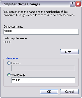
Enter in a computer name, and if required, a workgroup. Then press OK. You may need to restart the computer for these changes to take effect.
You will need to bind some protocols and services to your new network card. To do this in Windows 2000, right-click My Network Places→Properties→Local Area Connection→Properties. On Windows XP, click Control Panel→Network Connections→Local Area Connection.
In this box, you need to see three things: Client for Microsoft Networks, File and Printer Sharing for Microsoft Networks, and Internet Protocol (TCP/IP). If any of these is missing, press the Install button.
The next task is to set up the TCP/IP settings for the computer. To open the dialog box, highlight Internet Protocol (TCP/IP) and click Properties.
If this computer is part of a larger network, there may be a DHCP server on the network, which automatically assigns IP addresses. In this case, choose the options “Obtain an IP address automatically” and “Obtain DNS server address automatically.” Otherwise, set the fields manually.
You have to set the IP addresses as nonpublic addresses, and each computer must be assigned a unique IP address. A series of IP addresses could be 10.0.0.1, 10.0.0.2, 10.0.0.3, and so on. The subnet mask should be 255.255.255.0. Press OK to save the settings.
To share a folder, right-click on the folder, click Properties→Sharing. Click on Share this folder (on Windows XP, you will need to click on a disclaimer message, “If you understand the risk but still want to share the contents of this folder”).
Note
If you intend to accept Windows 9x clients, you will need to have a guest account on your system.
To limit remote users’ access to your files on Windows 2000, click Permissions. On the next window you can grant and revoke read, write, and change permissions to any or all users on the network. On Windows XP, this has been simplified to a checkbox, “Allow network users to change my files.”
Another useful feature of networks is the ability to remotely print documents. This section assumes that you have a printer attached to a computer on your network. On Windows 2000, click Start→Settings→Printers. On Windows XP, press Start→Control Panel→Printers and Faxes. Right-click on a printer that you would like to share, and select the Sharing option. Then select Shared As, enter a unique name, and a descriptive name for the printer. You can set the level of control users will have over the printer from the Security tab. Press OK to complete the process.
A virtual private network (VPN) is used to give a remote client secure access to a LAN. The remote client will have transparent (albeit, slower) access to the LAN and will be able to share files and use remote printers, and so forth.
A VPN operates over the point-to-point tunneling protocol (PPTP) or layer 2 tunneling protocol (L2TP). The local traffic is layered on top of this to support true transparency and support for nonroutable protocols such as IPX.
A VPN has some advantages over dial-in connections to a network. These are security, where every transmission is encrypted, and transparency, because the client can retain its own IP address.
To become a VPN client, on Windows 2000, click Start→Settings→Network Connections, and then click New Connection wizard. On Windows XP, click Start→Control Panel→Network Connections→Create a New Connection→Next.
Click on “Connect to a private network through the Internet” on Windows 2000 or “Connect to the network at my workplace,” then Virtual Private Network Connection on Windows XP.
When prompted, type in the IP address of the VPN gateway. This should be as supplied by the administrator of the VPN. Press Finish to finalize the settings.
Up to now, private IP addresses have been mentioned in passing, more by way of highlighting the fact that they exist, how to recognize them, and how to understand their limitations. In enterprise networks, it is unfeasible to supply every user with a separate direct connection to the Internet. It is normal to channel each user’s network connection to a gateway, and from here, a direct connection to the Internet exists.
The term gateway is generic. It simply means the device that is connected to both the internal network and the Internet. This can be either a computer or a stand-alone device. Both proxies and routers can function as a gateway. A proxy would be in the form of software running on a computer, and a router being a stand-alone device. A router is always preferable to a proxy in every respect, apart from cost.
If you have inherited a network running a proxy server that is experiencing performance problems or on which users are finding it difficult to run certain applications, then you should consider using a router instead of a proxy server.
A router is generally a piece of hardware. It performs minimal processing of packets. This means that a router can operate at speeds far exceeding those of a proxy server. It also steers packets in the right direction, instead of blindly sending them out to the next router up the chain. Furthermore, its presence is much more transparent to clients, and it has much higher resiliency.
If you look at the rear panel of a router, you will see several LAN connections: one marked WAN, a power lead, and possibly a serial connection. To wire one up, you connect the WAN port to the cable provided by your ISP. Each LAN port can be connected to a computer, or hub. You need to obtain the following information from your ISP:
What fixed IP address to use, or whether to obtain one via DHCP
The IP address of the default gateway
What subnet mask to use
The primary and secondary DNS
Each computer behind the router must then set its default gateway and DNS servers to the IP address of the gateway and set the IP addresses to private addresses.
A good analogy for a firewall is a switchboard operator for a company. If an unsolicited salesperson rings, chances are the operator will not forward the call through; however, if an employee makes an outgoing call to the salesperson, the operator will not block the call. Calls made from employees within the company go through the switchboard, so the caller ID that appears on the recipient’s phone will be that of the switchboard rather than the direct line.
A firewall performs this function, only at very high speeds, either in software or hardware. It is possible to buy stand-alone firewalls, but every modern router will contain some sort of firewall (sometimes referred to as packet filtering). A firewall can also come in the guise of software.
In Administrative Tools→Services, you will see the Internet Connection Firewall (ICF) service. You can press Start to enable this service. This will suffice to protect a single computer from the ravages of the Internet. There is no need to use this service if your local gateway uses a firewall.
Proxies should only be considered when you have no budget to develop a network or only two or three computers require an Internet connection. Proxies will slow down your Internet connection considerably.
First, if you expect to have multiple users sharing an Internet connection, you will need something more than a dial-up connection. ISDN would be the minimum, with DSL being a preferred option. You will have already created your LAN, with one computer equipped with a DSL modem of some description. This computer runs the proxy server software.
All other computers on the network have to use this computer as a via point to request Web pages and so forth. This means that every Internet-connecting program needs to know the IP address of the proxy. In Internet Explorer, this is set from Tools→Internet Options→Connections→LAN Settings→Use a proxy server.
Proxies come in two flavors: application proxies and circuit-level proxies. Application proxies normally accept only one protocol, such as HTTP. Circuit-level proxies can accept any protocol over IP. The most popular circuit-level proxy is known as SOCKS; a popular HTTP proxy is Wingate (www.wingate.com).
Some applications will only work with an HTTP proxy or SOCKS. It is generally a case of determining which applications you need to use and getting a proxy server to suit.
The SOCKS protocol is defined in RFC 1928. In order to use a SOCKS proxy, the client must first authenticate itself. This consists of an initial short (3-byte) negotiation followed by a vendor-specific subnegotiation. Once the client is authenticated, a packet to the outside world can be sent when preceded by a short (10-byte) header. This header includes the port and IP address of the destination. Responses are tagged with the same header, only reversed.
All gateways perform some sort of network address translation, or NAT. For simplicity’s sake, any device that implements NAT will also be referred to as a NAT. A NAT rewrites the IP header of packets leaving the network with a new, public IP address. When the response packet returns, the NAT will have remembered what computer had originally issued the request and rewrite the IP header with the appropriate private IP address.
A proxy server, although it can provide HTTP requests that emanate from a different IP address than the source, is not considered to implement NAT. This is because the input is different from the output in more ways than just the IP address. More specifically, a proxy server expects a header in the data sent to it to indicate the destination host and port. True NAT devices do not require this identification. When configuring a computer to use a NAT, it is only necessary to change the gateway and DNS settings (under TCP/IP settings) to allow all applications to communicate transparently through the NAT. With a proxy, there is no such global setting, and each application has to be configured independently.
NAT was developed by Cisco, but it is now an Internet standard (RFC 1631). Several different translations can be performed on network addresses, which can be used to provide more flexible gateways to the Internet. Not all gateway devices support the full range of NAT operations.
Static NAT is where every private IP address has its own corresponding public IP address. This means that each computer is distinguishable from the outside world, yet not necessarily accessible.
Dynamic NAT is where every private IP address is mapped to a unique public IP address, although not always the same one every time.
Overloading is the most common form of NAT (sometimes called port address translation). It maps every private IP address to a single public IP, but differentiates the connections by placing them on different local ports (multiplexing).
Overlapping is used when two LANs with different subnets are joined together. Every private IP on one network is mapped to a unique private IP on the second network, and vice versa. Overlapping can be done by using static or dynamic NAT. The latter is a more complex undertaking.
When there is a mixture of public and private IP addresses on the stub domain (a private LAN), the NAT will not perform any translation on public IP addresses, but the packets still pass through the device.
As mentioned previously, a NAT needs to store information about what packets it has sent out, so that it can appropriately return the replies. In dynamic NAT, an IP address mapping cannot change midway through a TCP/IP session. Therefore, a NAT also needs to store which TCP/IP session is mapped to each IP address. Because a computer can theoretically maintain a TCP/IP session on each port, a network of 100 computers could maintain 6 million concurrent sessions.
The number of clients a router can process should be stated by the manufacturer; however, as a rough estimate, every entry in the NAT translation table is 160 bytes long; therefore a router with 2 Mb of RAM could handle about 12,000 sessions, which is more than enough for any office network.
A device that implements NAT will probably also include some sort of packet filtering and logging to compliment it. After all, what is the point of providing the ultimate network if the users spend all of their time browsing pornographic Web sites (unless of course you’re in that industry)? Filtering can block various destination addresses, port numbers, and so forth. Logging will record packets entering and leaving the router, but not the internal nonroutable traffic. On large networks, a packet analyzer will have difficulty recording the activities of 100 users who all decide to ghost their machines at once.
Note
Ghost is a product developed by Symantec that can replicate hard disks over a network http://www.symantec.com/ghost/.
Even with its complexity, NAT eases system administration (e.g., if your server goes down, and you can’t get physical access to it). You can use the remote-access facility that comes standard on most routers to change the inbound mapping to point to the IP address of a server that you do have access to, and the problem will be solved, for Internet clients anyway.
In order to provide a backup Internet connection, you will require a second router. This router ensures that outgoing traffic to the backup ISP will be appropriately mapped. Providing both routers are interconnected, when one ISP fails, the other router will take all of the traffic from the other, and will do so without any human intervention. This type of arrangement is known as a multihomed network. This is made possible because of the various ways routers interoperate. They use the interborder gateway protocol (IGBP) to talk to each other inside a LAN and the exterior gateway protocol (EGP) to communicate with the ISP’s routers.
A piece of NAT software named Sygate is freely available, but hardware implementations are recommended
If your customer already has a functioning network, but your software doesn’t work on it, you can’t ignore the problem, or you will lose the sale.
There are always two ways to fix a problem: address it or avoid it. Both methods are equally valid and equally applicable to different situations. Take the situation where a teleconferencing application does not operate behind a firewall. You can either move the server outside the firewall, set up port forwarding to tunnel through the firewall (or router), or bounce data off a proxy server to avoid the firewall. The first two options may involve you going on-site to fix the problem, whereas the latter involves renting a dedicated server and doing some programming.
If you write an application for the mass market, you have to bear in mind that not all software users will have either direct or transparent connections to the Internet. In some cases, users may access the Internet via a proxy. Unfortunately, there is no foolproof means of detecting if a proxy is in use on a network, where it is, or what type it is.
Unlike routers, proxies are not transparent to clients. You will need to modify your code to account for a proxy. If you are using the HTTPWebRequest and are trying to navigate an application proxy, then this is relatively straightforward:
C#
WebProxy myProxy= new WebProxy("proxyserver",8080);
myProxy.BypassProxyOnLocal = true;
String url = "http://www.yahoo.com";
HttpWebRequest request =
(HttpWebRequest)HttpWebRequest.Create(url);
request.Proxy = myProxy;
VB.NET
Dim myProxy As WebProxy = New WebProxy("proxyserver", 8080)
myProxy.BypassProxyOnLocal = True
Dim url As String = "http://www.yahoo.com"
Dim request As HttpWebRequest = _
CType(HttpWebRequest.Create(url), _
  HttpWebRequest)
request.Proxy = myProxy
Note that the above code requires the System.Net namespace.
If a firewall is in place that blocks all ports, then you could make changes to the firewall to allow access on your requested port. Firewalls are generally accessed either through a Web interface (http://192.168.1.1 or similar) or via a serial connection. You will need to have the manual and passwords close at hand. Some routers offer port forwarding to bypass firewalls. This is where the data directed at the router’s IP address on a specified port is forwarded to a specified internal IP address. The process is transparent to both ends of the connection.
Finally, if you have no access to the firewall, or you want to provide a user-friendly solution, you can bounce data from a proxy. This is where the machine behind the firewall opens a steady TCP and connects to a proxy machine, which is outside of the firewall, and the proxy allows the client to connect to it. Data from the client to the proxy is forwarded via the previously opened connection. This is the technique used by Instant Messenger applications. A coded example of this solution is provided at the end of this chapter.
Prevention is always better than cure. If you are releasing a product into the wild, it is almost certain that some user will have such an unusual network configuration that your software won’t work. To them, their network isn’t unusual, and in fact a hundred other users out there have the same problem, but they didn’t bother to tell you that your software doesn’t work.
If your software can’t start on its default port, it should move to another port, or at least prompt the user to enter a new port. If you don’t provide this function, you will encounter one of two problems: (1) users will inevitably run software that uses the same port as yours and that they don’t want to stop using, or (2) firewalls may already be set up to allow traffic through some ports; even if your customer doesn’t use a firewall, their ISP might.
The client who is waiting to connect to your software will need to know that it has moved port. You could simply display a message box and ask the user to type in the new port, or you could use a DNS request (Chapter 12) to tell users which ports the server is listening on and connect to each in turn. Generally, this approach is overkill.
Another problem that is regularly encountered is dynamic IP addresses. This is where the IP address of the computer changes every time it goes online. Left unchecked, many applications will grab the local IP address when the application starts and assume that is will remain static for the lifetime of the application. When users have dial-up connections, they could obtain five different IP addresses in the space of an hour under normal usage (signing on and off the Internet). This situation poses a problem for server applications because there is no way a client can know where it should connect. This can be solved either on a case-by-case basis or by hosting an IP tracking mechanism.
Software such as “no-IP” can be used to map a dynamic IP address to a DNS name. The process of using this software is relatively straightforward, but it may be unfeasible to request software users to use this product to solve the dynamic IP address issue. The alternative is to have the computer periodically post its IP address to a server, whereupon the server will store the IP address, along with a timestamp and a human-readable identifier. Clients can look this up and connect to the dynamic IP address. The time-stamp ensures that offline computers will be deleted from the listing.
When posting an IP address, care must be taken to ensure that the IP is valid for the Internet. A LAN IP such as 192.168.0.1 is no good to a client on the other side of the world.
If you sell firewalls for a living, look away now because this section describes how to tunnel files (or any other data) through a firewall, in either direction, rendering the whole purpose of a firewall defunct. If you are developing a peer-to-peer application for the open market, however, this information opens up a whole new customer base.
To best illustrate the concept of firewall tunneling, let’s look at an analogy: Imagine two prisoners, one in Alcatraz and another in the Bastille. They can both make one phone call, but obviously, neither is allowed to receive calls. The prisoner in Alcatraz knows an escape route from the Bastille, which he wants to tell his partner in crime. How does he send the message? The prisoner in Alcatraz phones his friend’s home answering machine and leaves a message of where the escape route is located. The prisoner in the Bastille then makes his call to his own answering machine, where he hears the message and uses the information to escape.
The same technique is used to tunnel though firewalls. One user sends data to a publicly accessible server with a header indicating from whom the data came and who the intended recipient is. The recipient is constantly polling this server, querying it for any new messages. Once the data has been posted up to the server, the recipient can then download it and instruct the server to remove its copy.
The system could be implemented roughly by simply using an email account. Both computers would poll it using POP3 and post new messages using SMTP. Otherwise, Microsoft Message Queue (MSMQ) server (see Chapter 15) could be used for the same purpose.
Peer-to-peer (P2P) is a way of structuring distributed applications such that the individual nodes have symmetric roles. Rather than being divided into clients and servers, each with distinct roles (such as Web clients versus Web servers), in P2P applications a node may act as both a client and a server. P2P systems are generally deployable in an ad hoc fashion, without requiring centralized management or control. They can be highly autonomous and can lend themselves to anonymity.
In order to function correctly, each node on a P2P network must know the location of at least one other node. In some implementations, a node could contact an indexing server, which would return a list of other nodes on the P2P network. The benefit of P2P networks is that they are fault tolerant (i.e., there is no single point of failure), and the network can continue to operate smoothly even if several nodes are missing. Furthermore, the combined processing power and storage available across a multitude of nodes can greatly exceed what is practical to combine into one central server computer. Famous P2P software includes Napster and Kazaa.
This chapter should contain enough information to enable anyone to develop a simple LAN. More importantly, it illustrates network peculiarities of which a developer must be aware when developing distributed applications for enterprise environments.
With this information, it should be possible to develop an approach that will render the low-level network implementation details (such as private and dynamic IP addresses) transparent to higher-level processes.
The next chapter deals with data encryption and security. It explains how the industry-standard encryption mechanisms work and how they can be proclaimed to be “unbreakable.”