
You can’t always expect your customer to have the same bandwidth as your office LAN. Huge numbers of people still use modem connections, and some use mobile GPRS devices with even lower connection speeds.
These customers will only buy your software if it works at a speed that is at least usable and does not frustrate them. Online services with slow loading times will infuriate casual Web users and drive away potential customers. Conversely, people will pay more for better performance. To give an example, VNC (www.realvnc.com) is free, under general public license (GPL), whereas client licenses for Microsoft Terminal Services (MTS) are certainly not free. Both pieces of software allow you to control another computer remotely, but many people still opt for MTS. Why? Performance. MTS provides more fluid control over the remote computer than VNC over the same bandwidth.
This chapter is largely devoted to two different performance-enhancing techniques. The first section of the chapter covers a technology known as multicast, the ability to send one piece of data to more than one recipient simultaneously. The second section deals with data compression and decompression. This is the ability to convert a block of data into a smaller block of data and then return this to either an exact or near copy of the original data.
Performance increases can often be made by simple changes to how data is moved between client and server. In some cases, these techniques may not be applicable; however when used correctly, each of the following methods will help keep your data moving quickly.
Caching can increase network performance by storing frequently accessed static data in a location that provides faster data return than the normal access time for the static data. It is important that all three of the following criteria are met:
The data must be frequently accessed. There is no point in storing large datasets in memory or on disk when only one client will ever request it, once.
The data must not change as often as it is requested. The data should remain static for long periods, or else clients will receive outdated data.
The access time for cached data must be substantially faster than the access time to receive the data directly. It would defeat the purpose if a client were denied access to the data from its source and instead was redirected to a caching server that had to reprocess the data.
Data can be cached at any point between the client and server. Server-side caches can protect against out-of-date data, but they are slower than client-side caches. Client caches are very fast because the data is read from disk, not the network, but they are prone to out-of-date data. Proxy caches are a combination of the two. They can refresh their cache regularly when idle and can serve data faster because they will be on a local connection to the client. Old data on a proxy can be frustrating for a user because it is awkward to flush the cache of a proxy server manually.
Server caching can be extremely useful when data on the server needs to be processed before it can be sent to clients. A prime example of this is that when an ASP.NET page is uploaded to a server, it must be compiled before generating content that is sent to the client. It is extremely wasteful to have the server recompile the page every time it is requested, so the compiled version is held in a server-side cache.
When a site consists of mainly static content, it is possible to cache a compressed version of each of the pages to be delivered because most browsers can dynamically decompress content in the right format. Therefore, instead of sending the original version of each page, a compressed version could be sent. When the content is dynamic, it is possible to utilize on-the-fly compression from server-accelerator products such as Xcache and Pipeboost.
Caching introduces the problem of change monitoring, so that the cached data reflects the live data as accurately as possible. Where the data is in the form of files on disk, one of the simplest mechanisms is to compare the “date modified” field against the cached data. Above that, hashing could be used to monitor changes within datasets or other content.
Within the environment of a single Web site or application, caching can be controlled and predicted quite easily, except when the content to be served could come from arbitrary sources. This situation might arise in a generic caching proxy server, where content could come from anywhere on the Internet. In this case, the proxy must make an educated assessment about whether pages should be cached locally or not.
The proxy would need to hold an internal table, which could record all requests made to it from clients. The proxy would need to store the full HTTP request because many sites behave differently depending on what cookies and so forth are sent by the client. Along with the requests, the proxy would need to be able to count the number of identical requests and how recently they were made. The proxy should also keep checksums (or hashes) of the data returned from the server relative to each request. With this information, the proxy can determine if the content is too dynamic to cache. With that said, even the most static and frequently accessed sites change sometimes. The proxy could, during lull periods, check some of the currently cached Web sites against the live versions and update the cache accordingly.
Even though most Web pages contain many different images that all come from the same server, some older (HTTP 1.0) clients create new HTTP connections for each of the images. This is wasteful because the first HTTP connection is sufficient to send all of the images. Luckily, most browsers and servers are capable of handling HTTP 1.1 persistent connections. A client can request that a server keep a TCP connection open by specifying Connection: Keep-Alive in the HTTP header.
Netscape pioneered a technology that could send many disparate forms of data through the same HTTP connection. This system was called “server push” and could provide for simple video streaming in the days before Windows media. Server push was never adopted by Microsoft, and unfortunately it is not supported by Internet Explorer, but it is still available in Netscape Navigator.
When a TCP connection opens and closes, several handshake packets are sent back and forth between the client and server, which can waste up to one second per connection for modem users. If you are developing a proprietary protocol that involves multiple sequential requests and responses between client and server, you should always aim to keep the TCP connection open for as long as possible, rather than repeatedly opening and closing it with every request.
The whole handshake latency issue can be avoided completely by using a non-connection-oriented protocol such as UDP. As mentioned in Chapter 3, however, data integrity is endangered when transmitted over UDP. Some protocols such as real-time streaming protocol (RTSP, defined in RFC 2326) use a combination of TCP and UDP to achieve a compromise between speed and reliability.
When most of a file is downloaded, the client should be able to begin to use the data. The obvious applications are audio and video, where users can begin to see and hear the video clip before it is fully downloaded. The same technique is applicable in many scenarios. For instance, if product listings are being displayed as they are retrieved, a user could interrupt the process once the desired product is shown and proceed with the purchase.
Image formats such as JPEG and GIF come in a progressive version, which renders them as full-size images very soon after the first few hundred bytes are received. Subsequent bytes form a more distinct and higher-quality image. This technique is known as interlacing. Its equivalent in an online catalog application would be where product names and prices download first, followed by the images of the various products.
Windows is optimized by default for use on Ethernets, so where a production application is being rolled out to a client base using modems, ISDN, or DSL, some system tweaking can be done to help Windows manage the connection more efficiently and, ultimately, to increase overall network performance. Because these settings are systemwide, however, these changes should only be applied when the end-customer has given your software permission to do so.
The TCP/IP settings are held in the registry at
HKEY_LOCAL_MACHINESYSTEMCurrentControlSetServicesTcpipParameters
Under this location, various parameters can be seen, such as default name servers and gateways, which would otherwise be inaccessible programmatically. Not all of these parameters would already be present in the registry by default, but they could be added when required.
The first system tweak is the TCP window size, which can be set at the following registry location:
HKLMSYSTEMCurrentControlSetServicesTcpipParameters
GlobalMaxTcpWindowSize
The TCP window specifies the number of bytes that a sending computer can transmit without receiving an ACK. The recommended value is 256,960. Other values to try are 372,300, 186,880, 93,440, 64,240, and 32,120. The valid range is from the maximum segment size (MSS) to 230. For best results, the size has to be a multiple of MSS lower than 65,535 times a scale factor that’s a power of 2. The MSS is generally roughly equal to the maximum transmission unit (MTU), as described later. This tweak reduces protocol overhead by eliminating part of the safety net and trimming some of the time involved in the turnaround of an ACK.
TcpWindowSize can also exist under ParametersInterface. If the setting is added at this location, it overrides the global setting. When the window size is less than 64K, the Tcp1323Opts setting should be applied as detailed below:
HKLMSYSTEMCurrentControlSetServicesTcpipParametersTcp1323Opts
“Tcp1323” refers to RFC 1323, a proposal to add timestamps to packets to aid out-of-order deliveries. Removing timestamps shaves off 12 bytes per TCP/IP packet, but reduces reliability over bad connections. It also affects TCP window scaling, as mentioned above. Zero is the recommended option for higher performance. Set the size to one to include window-scaling features and three to apply the timestamp. This setting is particularly risky and should not be tampered with without great care.
The issue of packets with a time-to-live (TTL) value is discussed again in the multicast section in this chapter, where it is of particular importance. The setting can be applied on a systemwide level at this registry location:
HKLMSYSTEMCurrentControlSetServicesTcpipParametersDefaultTTL
The TTL of a packet is a measure of how many routers a packet will travel through before being discarded. An excessively high TTL (e.g., 255) will cause delays, especially over bad links. A low TTL will cause some packets to be discarded before they reach their destination. The recommended value is 64.
The MTU is the maximum size of any packet sent over the wire. If it is set too high, lost packets will take longer to retransmit and may get fragmented. If the MTU is set too low, data becomes swamped with overhead and takes longer to send. Ethernet connections use a default of 1,500 bytes per packet; ADSL uses 1,492 bytes per packet; and FDDI uses 8,000 bytes per packet. The MTU value can be left as the default or can be negotiated at startup. The registry key in question is
HKLMSYSTEMCurrentControlSetServicesTcpipParametersEnablePMTUDiscovery
The recommended value is one.This will make the computer negotiate with the NIC miniport driver for the best value for MTU on initial transmission. This may cause a slow startup effect, but it will ultimately be beneficial if there should be little packet loss and the data being transferred is large.
Ideally, every piece of datagram being sent should be the size of the MTU. If it is any larger than the MTU, the datagram will fragment, which takes computing time and increases the risk of datagram loss. This setting is highly recommended for modem users:
HKLMSYSTEMCurrentControlSetServicesTcpipParametersEnablePMTUBHDetect
The recommended setting is zero. Setting this parameter to one (True) enables “black hole” routers to be detected; however, it also increases the maximum number of retransmissions for a given TCP data segment. A black hole router is one that fails to deliver packets and does not report the failure to the sender with an ICMP message. If black hole routers are not an issue on the network, they can be ignored.
HKLMSYSTEMCurrentControlSetServicesTcpipParametersSackOpts
The recommended setting is one. This enables Selective Acknowledgement (SACK) to take place, which can improve performance where window sizes are low.
HKLMSYSTEMCurrentControlSetServicesTcpipParametersTcpMaxDupAcks
The recommended value is two. The parameter determines the number of duplicate acknowledgments that must be received for the same sequence number of sent data before “fast retransmit” is triggered to resend the segment that has been dropped in transit. This setting is of particular importance on links where a high potential for packet loss exists.
Moving outside the low-level TCP nuts and bolts, a setting can improve the performance of outgoing HTTP connections. These settings can speed up activities such as Web browsing:
HKEY_USERS.DEFAULTSoftwareMicrosoftWindows
CurrentVersionInternet Settings
"MaxConnectionsPerServer"=dword:00000020
"MaxConnectionsPer1_0Server"=dword:00000020

HKEY_CURRENT_USERSoftwareMicrosoftWindowsCurrentVersion
Internet Settings
"MaxConnectionsPerServer"=dword:00000020
"MaxConnectionsPer1_0Server"=dword:00000020
This setting actually increases the number of concurrent outgoing connections that can be made from the same client to the one server. This is a (small) violation of the HTTP standard and can put undue strain on some Web servers, but the bottom line is, if it makes your application run faster, who cares?
Multicasting is where a message can travel to more than one destination at the same time. This can provide significant increases in efficiency where there is more than one recipient of the data being sent. It is ideally suited to networks where all clients and servers are on the same LAN, and it is routable on the Internet, but is only supported by some service providers.
The first audio multicast took place in 1992, followed one year later by the first video multicast. Nowadays, multicast UDP is used in products such as Symantec Ghost to provide remote software installations on multiple hosts simultaneously. It is also used to broadcast video footage of popular events over the Internet.
From a programmer’s perspective, the difference between point-to-point UDP and multicast UDP is minimal. In .NET, we use the UDPClient object and call the JoinMulticastGroup() method, passing to it a multicast IP address. We can then send and receive packets using the same methods as we would with a standard UDP connection.
A multicast IP address is one that lies in the range 224.0.0.0 to 239.255.255.255. Unfortunately, you can’t pick any multicast IP address arbitrarily because there are some restrictions. The IANA controls multicast IP addresses, so you should consult RFC 3171 and the IANA Web site for a definitive list. Never use a multicast IP address that is already assigned to a well-known purpose, such as the following:
224.0.0.0 to 224.0.0.255: The Local Network Control Block is nonroutable and cannot travel over the Internet. These addresses have well-known purposes (e.g., DHCP is on address 224.0.0.12).
224.0.1.0 to 224.0.1.255: The Internetwork Control Block is routable, but these addresses have special uses. Network time protocol (NTP) is on address 224.0.1.1, and WINS is on address 224.0.1.24.
239.0.0.0 to 239.255.255.255: The scope-relative addresses are not routable, but they have no special purpose and can be used freely for experimental purposes.
It is possible to request a globally unique multicast IP address from the IANA. Initially, you should use an experimental multicast address such as 234.5.6.11 or obtain a leased multicast address from multicast address dynamic client allocation protocol (MADCAP), as defined in RFC 2730.
If other people are using the same multicast address as you, you may receive stray packets that could corrupt the data you are trying to transmit. If you are broadcasting exclusively to a LAN, use a scope-relative address.
When broadcasting on a WAN (but not the Internet), you can limit the TTL of the packet to less than 63. TTL prevents a packet from being routed indefinitely. Every hop decreases the TTL by one. When the TTL reaches zero, the packet is discarded. This can confine a packet to a geographic area and also prevents multicast avalanches, which occur when packets are replicated exponentially and end up clogging routers all over the Internet.
Multicast UDP may be the first non-P2P protocol to be accessible programmatically, but there is nothing new in protocols that broadcast rather than going from A to B. Routing protocols such as RIP and OSPF do not have set endpoints; rather, they percolate through networks in all directions at once. In fact, it would be a paradox if a routing protocol needed to be routed from point to point. The technique is not limited to routing protocols (e.g., BOOTP [bootstrap] and ARP are other examples of nondirectional protocols).
The biggest limitation of network broadcasts is that they generally only work within the same LAN and cannot be routed across the Internet. Multicast UDP goes partway toward solving this problem. It is true that not everyone can send or receive multicasts to or from the Internet. Multicast data does have a tendency to flood networks, so not all service providers want to be bombarded with unsolicited data. To enable service providers who do accept multicast to communicate, the multicast backbone (MBONE) was developed. This links multicast-compatible providers together via point-to-point channels in non-multicast-compatible networks. It currently spans more than 24 countries, mostly in academic networks.
Multicast implies that data travels in all directions at once (floods), but in practice, it is not the UDP packets that flood, but multicast routing protocol packets that do this job for them. There are three multicast routing protocols: distance vector multicast routing (DVMRP), multicast open shortest path first (MOSPF), and protocol independent multicast (PIM). A subscriber to a multicast will issue an Internet group management protocol (IGMP) packet to register its interest in receiving messages. This protocol is also used to leave groups.
There is no equivalent multicast TCP because of the constant one-to-one handshaking that is required. This causes some difficulties for application developers because data sent by UDP can be corrupted as a result of packet loss, duplication, and reordering. This problem can be counteracted by inserting headers in the data containing a sequence number, which the client can reorganize or request a once-off TCP/IP transfer of the missing packet from the server.
Similarly, it is difficult to implement public/private key security via multicast because every client would have a different public key. The IETF is scheduled to publish a standard security mechanism over multicast (MSEC) to address this issue.
Before you can implement a multicast-enabled application, you should ensure that your Internet connection supports multicast traffic and is connected to the MBONE network.
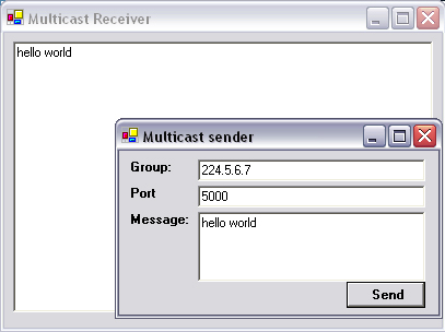
This example consists of two applications: a sender and a receiver. We start with the implementation of the sender. Open a new project in Visual Studio .NET and add three textboxes: tbMulticastGroup, tbPort, and tbMessage. You will also require a button named btnSend.
Click on the Send button, and add the following code:
C#
private void btnSend_Click(object sender, System.EventArgs e)
{
  send(tbMulticastGroup.Text , int.Parse(tbPort.Text),
  tbMessage.Text );
}
VB.NET
Private  Sub btnSend_Click(ByVal sender As Object, _
    ByVal e As System.EventArgs)
  send(tbMulticastGroup.Text,Integer.Parse(tbPort.Text), _
    tbMessage.Text)
End Sub
Multicast operation can be performed at both the socket level and UdpClient level. To illustrate both techniques, the sender (client) will be implemented using sockets, whereas the receiver will be implemented using the UdpClient object. Before sending or receiving from a multicast group, it is necessary to join the group. This is done in the example below using the socket option AddMembership.
In the same way as if the socket was operating in point-to-point (unicast) mode, the remote endpoint must be specified with both a port and an IP address. The IP address in this case must be valid and within the multicast range (224.0.0.0 to 239.255.255.255). The TTL specifies how far the packet can travel; in this case, it is set to the maximum, 255.
The next step is to implement the Send function as follows:
C#
public void send(string mcastGroup, int port, string message)

{
  IPAddress ip=IPAddress.Parse(mcastGroup);
  Socket s=new Socket(AddressFamily.InterNetwork,
    SocketType.Dgram, ProtocolType.Udp);
  s.SetSocketOption(SocketOptionLevel.IP,
    SocketOptionName.AddMembership, new MulticastOption(ip));
  s.SetSocketOption(SocketOptionLevel.IP,
    SocketOptionName.MulticastTimeToLive, 255);
  byte[] b;
  b = Encoding.ASCII.GetBytes(message);
  IPEndPoint ipep=new IPEndPoint(
  IPAddress.Parse(mcastGroup), port);
  s.Connect(ipep);
  s.Send(b,b.Length,SocketFlags.None);
  s.Close();
}
VB.NET
Public  Sub send(ByVal mcastGroup As String, _
  ByVal port As Integer, ByVal message As String)
  Dim ip As IPAddress = IPAddress.Parse(mcastGroup)
  Dim s As Socket = New Socket(AddressFamily.InterNetwork, _
  SocketType.Dgram, ProtocolType.Udp)
  s.SetSocketOption(SocketOptionLevel.IP, _
  SocketOptionName.AddMembership, New MulticastOption(ip))
  s.SetSocketOption(SocketOptionLevel.IP, _
  SocketOptionName.MulticastTimeToLive, 255)
  Dim b As Byte()
  b = Encoding.ASCII.GetBytes(Message)
  Dim ipep As IPEndPoint = New _
  IPEndPoint(IPAddress.Parse(mcastGroup), port)
  s.Connect(ipep)
  s.Send(b, b.Length, SocketFlags.None)
  s.Close()
End Sub
This code uses sockets rather than streams to send multicast data. Several parameters need to be applied to the newly created code in order for it to operate effectively in multicast mode. First, the protocol type is set to UDP with ProtocolType.Udp because this is the underlying protocol for all multicast broadcasts.
A socket option is then set such that the socket will request to join the specified group. The option SocketOptionName.AddMembership indicates that the socket is attaching to a multicast group. The final parameter is the TTL; in this case, the TTL is 255, which effectively means that the packet(s) can travel anywhere in the world.
The message, which is in string format, is converted to a byte array. The endpoint is set to the multicast address on the port specified. The socket then connects to the endpoint, sends the byte array, and then disconnects.
To complete the program, add the required namespaces at the top of the code:
C#
using System.Text;
using System.Net;
using System.Net.Sockets;
VB.NET
Imports System.Text
Imports System.Net
Imports System.Net.Sockets
The next step is to code the multicast receiver. Open a new project in Visual Studio .NET and draw a textbox named tbMessages with multiline set to true on the form.
C#
private void Form1_Load(object sender, System.EventArgs e)
{
  Thread thdReceiver = new Thread(new
  ThreadStart(receiverThread));
  thdReceiver.Start();
}
VB.NET
Private  Sub Form1_Load(ByVal sender As Object, _
    ByVal e As System.EventArgs)
  Dim thdReceiver As Thread
  thdReceiver = New Thread(New ThreadStart _
     (AddressOf receiverThread))
  thdReceiver.Start()
End Sub
The receiving thread will remain in an infinite loop awaiting new data. It is therefore run in a separate thread named recieverThread().
In this case, the multicast functionality is implemented using the UdpClient object. Membership to the group is obtained by calling the JoinMulticastGroup. Again the TTL and port details must be specified.
Enter the following code to finish this application:
C#
public void receiverThread()
{
  UdpClient client = new UdpClient(5000);
  IPAddress group = IPAddress.Parse("224.5.4.6");
  int timeToLive = 255;
  int port = 5000;
  client.JoinMulticastGroup(group, timeToLive);
  IPEndPoint remoteEP = new IPEndPoint(group, port);
  while (true)
  {
    IPEndPoint ep = null;
    byte[] buffer = client.Receive(ref ep);
    string message = Encoding.ASCII.GetString(buffer);
    this.tbMessages.Text += message + "
";
  }
}Public Sub receiverThread()
Dim client As UdpClient = New UdpClient(5000)
Dim group As IPAddress = IPAddress.Parse("224.5.4.6")
Dim timeToLive As Integer = 255
Dim port As Integer = 5000
client.JoinMulticastGroup(group, timeToLive)
Dim remoteEP As IPEndPoint = New IPEndPoint(group,port)
Do
Dim ep As IPEndPoint = Nothing
Dim buffer() As Byte = client.Receive( ep)
Dim message as String = _
System.Text.Encoding.ASCII.GetString(buffer)
Me.tbMessages.Text += message + vbcrlf
Loop
End SubThis code uses a higher level of abstraction than the sender and implements a multicast receiver using UdpClient objects rather than bare sockets. In much the same way as you would receive standard UDP packets, the UdpClient is set to listen on a specified port (in this case, 5000) by passing the port number to the constructor. Where it differs is when JoinMulticastGroup is called. This method is passed an IPAddress object that holds the multicast IP address and the TTL value for any packets sent. The program goes into an infinite loop at this point, receiving arrays of bytes from whomever happens also to be transmitting on that multicast IP address. These byte arrays are then converted into strings and displayed on-screen.
To finish this code, add the required namespaces as follows:
C#
using System.Threading;
using System.Net;
using System.Net.Sockets;
using System.Text;
Imports System.Threading
Imports System.Net
Imports System.Net.Sockets
Imports System.Text
To test this application, run both the sender and receiver from Visual Studio .NET. Set the group address on the sender to 224.5.6.7 and the port to 5000, type in a short message, and press send. You will see the text appearing in the receiver application (Figure 11.1). It should be possible to open multiple instances of the receiver application and have them all receive the same text simultaneously.
The most effective way to send data between computers faster is to send less data. This does not mean that you send the recipient less information, just that it is packaged in a more compact way. The process of compressing data so that the decompressed data is identical to the original is known as lossless compression and is used in ZIP compression. The process of compressing data in a way that is not identical, but is not perceived as different from the original, is known as lossy compression and is used in JPEG and Mp3 compression.
Lossless compression is used when the integrity of data is paramount. In the same way that it saves space to round the company’s annual returns to the nearest million, there may be a risk that someone could run off with $499,999 without affecting the books.
There are two ways of compressing data without losing integrity: entropy encoding and source encoding. Entropy encoding is where the statistical similarity between bytes or byte sequences is recorded, rather than the bytes themselves. Source encoding is where the rate of change between bytes or byte sequences is recorded and not the bytes themselves. Entropy encoding is used in the ZIP format, whereas source encoding is used in adaptive delta pulse code modulation (ADPCM), an audio compression technique.
The most basic form of entropy encoding is run length encoding (RLE), where a byte sequence consisting entirely of the same byte is converted into a number followed by the byte. Therefore, the sequence (in hex) 00 00 00 00 00 could be shortened to 05 00. This approach achieves compression only on files with very high entropy, but it was used effectively in the rather outdated PCX format.
A more effective component of ZIP compression is Huffman compression, where the most common bytes are encoded into short bit sequences. The less common bytes are encoded into bit sequences longer than a byte, but because they are less common, the overall effect is a shorter file.
A table of bit-code-to-byte conversions is known as a codebook, which can be either static or dynamic. Because the codebook adds to the total length of the transmitted file, it is advantageous to have a short codebook or no codebook with a static codebook. There is no need to transmit the codebook with the data because the receiver will already have it.
Static codebooks have been around for years, in fact, since well before the time of computers. The first data compression scheme was Morse code. The designers of Morse code may not have had entropy reduction in mind, but they did happen to choose the shortest codes for the most common letters. E and T are encoded as a single dot and dash, whereas Z is encoded as a four “bit” sequence. Morse code is not applicable for computer data compression because it uses a pause as a delimiter, which cannot be represented in binary.
Dynamic codebooks are built up during compression, which is where the most common characters are ascertained and then assigned bit sequences. The codebook is then used to compress the data bytes into shorter bit sequences, which are joined together and padded to form a byte stream that should be smaller than the original data.
Codebooks cannot be built up arbitrarily. They must reflect the frequency of each character in the data and be easily delimitable. The simplest scheme is to assign a two-bit sequence to the most common character (i.e., 01). Each byte that follows this character frequencywise is represented by either an additional 1 or 00.
In English text, the most common character is a space, followed by e and then “t.” Therefore, a space can be represented as 01, “e” as 011, and “t” as 0100. Using this method, the sequence “e et” (6 bytes) can be represented as 01101010 10110100 (2 bytes). The process of building up a Huffman codebook (or “tree”) is not processor intensive, and it is possible to implement in real time to provide higher effective bandwidth to clients.
It is not necessary to reinvent the wheel when it comes to ZIP compression. Many third-party controls are available for download on the Internet. Some of these are under GPL and, thus, can be redistributed in binary (closed-source) form, once the license terms, as specified on the publisher’s Web site, are adhered to. A good implementation of ZIP in .NET is the #ZipLib from www.icsharpcode.net. The following example demonstrates how to compress a file using #ZipLib, so it is worthwhile to download it from their Web site.
Where using third-party code is not an option, the official reference for the ZIP format is located in RFC 1950 through RFC 1952.
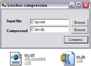
Create a new project in Visual Studio .NET, click Projects→Add References→Browse, and then select SharpZipLib.dll from the folder where #ZipLib was installed. Draw two textboxes named tbInput and tbOutput on the form with two corresponding buttons, btnBrowseInput and btnBrowseOutput. The two browse buttons should have corresponding File Open and File Save Dialog controls, OpenFileDialog and SaveFileDialog, respectively. Finally, a button named btnCompress is also required.
The first step is to tie the File Open and File Save dialog boxes to the buttons, to make it easier for users to select the relevant files. Click on the Browse button opposite the Input textbox and enter the following code:
private void btnBrowseInput_Click(object sender,
System.EventArgs e)
{
  openFileDialog.ShowDialog();
  tbInput.Text = openFileDialog.FileName;
}
VB.NET
Private  Sub btnBrowseInput_Click(ByVal sender As Object, _
    ByVal e As System.EventArgs)
  openFileDialog.ShowDialog()
  tbInput.Text = openFileDialog.FileName
End Sub
Click on the Browse button opposite the Output textbox and enter the following code:
C#
private void btnBrowseOutput_Click(object sender,
System.EventArgs e)
{
  saveFileDialog.ShowDialog();
  tbOutput.Text = saveFileDialog.FileName;
}
VB.NET
Private  Sub btnBrowseOutput_Click(ByVal sender As Object, _
    ByVal e As System.EventArgs)
  saveFileDialog.ShowDialog()
  tbOutput.Text = saveFileDialog.FileName
End Sub
The workhorse of the application is contained behind the Compress button. ZIP files can contain more than one source file and retain CRC and date information with each file to help maintain integrity. The ZipOutputStream is appended to using ZipEntry objects. Each entry contains the original file data, along with a CRC for that file and a date.
Note
Checksums (or CRCs) are similar to hash values, although they are used for integrity checks rather than security against data tampering.
The SetLevel method is used to define the strength of compression, where zero is no compression and nine is maximum compression. There is a small performance difference between the compression levels, but in most cases, it should be set to maximum.
Click on the Compress button and enter the following code:
C#
private void btnCompress_Click(object sender,
System.EventArgs e)
{
  Crc32 crc = new Crc32();
  ZipOutputStream ZipStream =
    new ZipOutputStream(File.Create(tbOutput.Text));
  ZipStream.SetLevel(9);
  string file = tbInput.Text;
  FileStream fs = File.OpenRead(file);
  byte[] buffer = new byte[fs.Length];
  fs.Read(buffer, 0, buffer.Length);
  ZipEntry entry = new ZipEntry(file);
  entry.DateTime = DateTime.Now;
  entry.Size = fs.Length;
  fs.Close();
  crc.Reset();
  crc.Update(buffer);
  entry.Crc  = crc.Value;
  ZipStream.PutNextEntry(entry);
  ZipStream.Write(buffer, 0, buffer.Length);
  ZipStream.Finish();
  ZipStream.Close();
}
VB.NET
Private  Sub btnCompress_Click(ByVal sender As Object, _
 ByVal e As System.EventArgs)
      Dim crc As Crc32 = New Crc32
        Dim ZipStream As ZipOutputStream = _
           New ZipOutputStream( _
           System.IO.File.Create(tbOutput.Text))
        ZipStream.SetLevel(9)
        Dim file As String = tbInput.Text
        Dim fs As FileStream = System.IO.File.OpenRead(file)
        Dim buffer() As Byte = New Byte(fs.Length) {}
        fs.Read(buffer, 0, buffer.Length)
        Dim enTry As ZipEnTry = New ZipEnTry(file)
        enTry.DateTime = DateTime.Now
        enTry.Size = fs.Length + 1
        fs.Close()
        crc.Reset()
        crc.Update(buffer)
        enTry.Crc = crc.Value
        ZipStream.PutNextEnTry(enTry)
        ZipStream.Write(buffer, 0, buffer.Length)
        ZipStream.Finish()
        ZipStream.Close()
End Sub
ZIP files consist of multiple entries, one entry for each file. Each entry has an associated CRC value, which is analogous to a hash value in proving integrity checks for files that could have been corrupted in transit. Creating a ZIP file takes three steps: (1) creating a zip stream, (2) defining the various entries, and (3) calculating the CRC values for each entry.
The zip stream is created with a constructor that is passed the final destination of the .zip file. The compression level is also set at this point: level 1 is fast, but offers little compression, whereas level 9 is slower, but offers better compression ratios.
The second step is to create an entry for the file that is to be compressed. Here a new ZipEntry object is instantiated. The constructor of this object is passed the filename and the path for the file to be compressed. The file’s date and length are included in the entry. This entry is appended to the stream using the PutNextEntry method.
Every entry must have a corresponding CRC value. This value is calculated by first reading in the contents of the file and then passing the resultant byte array to the Update method of a Crc32 object. The CRC value is stored in the crc property of the entry.
The ZIP file is written to disk, one entry at a time, by passing the contents of the uncompressed file to the Write method of the zip stream. Finally, the stream is flushed with the Finish command and then closed.
Add the following assemblies at the top of the code:
C#
using ICSharpCode.SharpZipLib.Checksums;
using ICSharpCode.SharpZipLib.Zip;
using ICSharpCode.SharpZipLib.GZip;
using System.IO;
VB.NET
Imports ICSharpCode.SharpZipLib.Checksums
Imports ICSharpCode.SharpZipLib.Zip
Imports ICSharpCode.SharpZipLib.GZip
Imports System.IO
To test the application, run it from Visual Studio .NET. Press the Browse button beside the Input textbox and select a text file from your computer. Press the second Browse button and enter a filename with the extension .zip. Press Compress, and then locate the newly created ZIP file. You should notice a reduction in file size (Figure 11.2).
Examples of decompressing ZIP files and more advanced uses of this control may be found at the www.icSharpcode.net Web site. Interested readers should refer to this site for more information. In Chapter 4, a certain HTTP header may have particular relevance to developers working on Web-based applications that have browsers as clients. Specifically:
Accept-Encoding: gzip, deflate
As the name suggests, browsers can accept compressed data as well as plain text. Therefore, it is possible to improve the performance of a Web server by compressing its output, either on the fly or in cache compression.
The gzip and deflate compression algorithms are contained within the #ZipLib control, so furnishing this format to clients is easy. All that is required in addition to the compression aspect is that Content-Encoding is added to the header in the HTTP reply. An open-source implementation of this was developed by Ben Lowery and can be found at: www.blowery.org/stories/2002/12/12/httpcompressionmodule.html.
In cases where data integrity is not as important, but good compression is imperative, lossy compression is a good option. This is particularly pertinent to audio and visual data, where users will put up with a little muffling or blurring, as long as they see or hear what they want without having to wait too long.
An audio file has very little byte-to-byte entropy, and compression schemes such as ZIP or Huffman will have little effect on the file size; however, if you open an audio file in a wave editor, such as Goldwave (www.goldwave.com), you will notice a definite pattern when you look closely at the data in Figure 11.3.
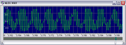
The screenshot is of a recording of a girl’s voice. It contains only a fraction of a second (0.026 sec) of audio, but contains more than 2 Kb of data. To achieve CD-quality audio, a computer must output data at 44,100 (× 2) bytes per second.
Audio is made up of waves. Each sample in a wave is usually very similar to the preceding sample. The rate of change constantly increases and decreases in harmonic fashion. Therefore, instead of recoding the value of each sample, if the change between samples is recorded, then the amount of data is reduced.
In delta pulse code modulation (DPCM), an increase in sample value is represented by the bit 1 and a decrease is represented by the bit 0. During decompression, the sample value is incremented or decremented by 1, depending on the value of the current bit in the bitstream. This causes two detrimental effects: slope overload and granular noise. Slope overload is where the input signal changes substantially from sample to sample, resulting in a muffling effect in the decompressed signal. Granular noise is where the input signal does not change at all, in which case the output sound oscillates around the true value, which causes either a hiss or a high-pitched shrill in the audio.
To counteract the muffling effect, adaptive DPCM, or ADPCM, can be used. This is where, during the decompression process, a number that doubles with each contiguous sample increases the sample value. This process more closely mimics the harmonic action of the sine wave, but can produce a phase undershoot, which is a rasping, sharp noise.
You may never have heard of ADPCM (although it is used heavily in telecommunications and especially on international telephone lines), but Mp3 has become almost a household name. There is a good reason for this, in that Mp3 provides excellent compression ratios and acceptable sound quality and can be decompressed in real time by any PC and many portable digital music devices. Mp3 achieves this quality by recognizing how humans perceive sounds at an acoustic level. Our ears are designed to hear harmonic sounds, and standard lossy compression algorithms cause unnatural attenuations that are not pleasant to listen to. By filtering at the harmonic level, rather than at the byte level, a much more natural sound is produced.
Recognizing a pattern of cyclic values in a stream of data, which may be combined with thousands of other cyclic patterns, is not an easy task for a computer; however, a rather gifted mathematician developed a formula to produce a mathematical representation of the harmonics contained in a block of data.
In Figure 11.3, a pattern of waves can be seen in the audio; these are made primarily from a 300 Hz with a 2400 Hz harmonic. To extract this information from what appears to the computer as a block of ones and zeros, you need to use a mathematical formula known as the Discrete Cosine Transform (DCT):
Cu is equal to 0.7071 (the reciprocal of root 2); when u is zero, Cu is one, for all u not equal to zero.
When the above formula is applied to an array of eight numbers (i.e., f(1) to f(7)), the resultant array in S is a representation of the data in terms of frequencies. It is possible to represent any sequence of eight integers in terms of the values of the peaks and troughs of a wave composed of up to eight harmonics. When compressing audio data, most of the higher harmonics are zero or near zero and can be canceled out; thus the array in S can be compressed using traditional lossless encoding more efficiently.
The most famous audio compression format that uses DCT is the ubiquitous Mp3. This technology is not an easy implementation, and its exact format is a closely guarded secret. You can use third-party DLLs and applications such as Lame, BladeEnc, and L3enc to perform the compression. Alternately, you can license the technology from Fraunhoffer.
Image compression is remarkably similar to audio compression, except that it works in two dimensions rather than one. There may not be the same obvious wave pattern in images, but in digital photographs the natural dithering in shades of color compresses very well when DCT/Huffman compression is applied.
During the JPEG compression process, the image is split into macroblocks, or 8×8 blocks of pixels. Each macroblock is then compressed using a two-dimensional DCT to isolate and reduce the number of color harmonics within each area of the picture. The idea of waves existing within an image may seem alien, but they exist everywhere in natural textures.
The two-dimensional DCT can be expressed mathematically as follows:
Cu is equal to 0.7071 (the reciprocal of root 2); when u is zero, Cu is one for all u not equal to zero. The same applies to Cv.
This formula produces a two-dimensional array, which can be compressed by rounding the near-zero values of the array to zero, then using RLE compression followed by Huffman compression.
Luckily, you will probably never have to implement JPEG compression from scratch. .NET has native support for JPEG, along with plenty of other image formats, including PNG, TIFF, and GIF. The following sample program shows you how to compress a bitmap image into a JPEG.
Start a new project in Visual Studio .NET. Draw a picture box, named pictureBox onto the form. Draw two textboxes named tbInput and tbOutput on the form, with two corresponding buttons, btnBrowseInput and btnBrowseOutput. The two browse buttons should have corresponding File Open and File Save Dialog controls, named openFileDialog and saveFileDialog, respectively. Finally, a button named btnCompress is also required.
The first step is to tie the File Open and File Save dialog boxes to the buttons to make it easier for users to select the relevant files. The open file procedure will also load the new image into the picture box.
Click on the Browse button opposite the Input textbox and enter the following code:
C#
private void btnBrowseInput_Click(object sender,
System.EventArgs e)
{
  openFileDialog.ShowDialog();
  tbInput.Text = openFileDialog.FileName;
  pictureBox.Image= Image.FromFile(openFileDialog.FileName);

}Private Sub btnBrowseInput_Click(ByVal sender As Object, _ ByVal e As System.EventArgs) openFileDialog.ShowDialog() tbInput.Text = openFileDialog.FileName pictureBox.Image= Image.FromFile(openFileDialog.FileName) End Sub
Click on the Browse button opposite the Output textbox and enter the following code:
C#
private void btnBrowseOutput_Click(object sender,
System.EventArgs e)
{
  saveFileDialog.ShowDialog();
  tbOutput.Text = saveFileDialog.FileName;
}
VB.NET
Private  Sub btnBrowseOutput_Click(ByVal sender As Object, _
  ByVal e As System.EventArgs)
  saveFileDialog.ShowDialog()
  tbOutput.Text = saveFileDialog.FileName
End Sub
To save a JPEG from a loaded image, you may simply call the Save method. The method requires the image format and a stream as input parameters:
C#
private void btnCompress_Click(object sender,
System.EventArgs e)
{
  FileStream fs = new
  FileStream(tbOutput.Text,FileMode.CreateNew);
  PictureBox.Image.Save(fs,
  System.Drawing.Imaging.ImageFormat.Jpeg);
  fs.Close();
}Private Sub btnCompress_Click(ByVal sender As Object, _ ByVal e As System.EventArgs) Dim fs As FileStream = New FileStream(tbOutput.Text, _ FileMode.CreateNew) PictureBox.Image.Save(fs, _ System.Drawing.Imaging.ImageFormat.Jpeg) fs.Close() End Sub
To test this application, run it from Visual Studio .NET, press the Browse button next to the Input textbox, and choose a bitmap from your computer. Click the Browse button next to the Output textbox, and select a location to save the JPEG. Press Compress, and then locate the new saved JPEG on your computer; you should notice that it will have a smaller file size (Figure 11.4).
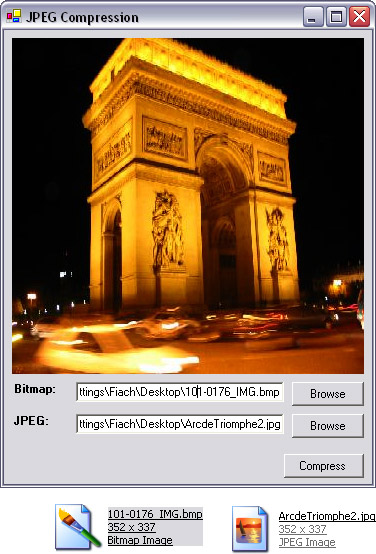
You may notice that it is possible to take a JPEG file as an input to this program. Although the application will allow you to do this, the end result will be a JPEG file of even lower quality than the original.
With a healthy percentage of consumers using broadband technology in their homes, it will soon be possible to deliver video on demand to the average user. Without compression, the bandwidths required would be phenomenal. Various standards have been developed to compress video data into narrower channels, the most successful of which is Motion Pictures Expert Group (MPEG). MPEG encoders are not cheap, but they do provide the best compression of any other format.
A cheap alternative to MPEG is the audio-video interleaved (AVI) format. This is a technology built in to the Windows API. It has nowhere near the same compressing capabilities, but it saves time in developing a proprietary format. A good resource for creating AVI files programmatically is www.shrinkwrapvb.com. The code examples are in Visual Basic 6.0, but they can be ported to VB.NET from within Visual Studio .NET.
If a proprietary format is the only option, then examining the operation of MPEG or MJPEG may help. Video compression is similar to audio compression, except there are three data channels for imaging and one channel for audio. Every pixel is made from a combination of three colors: red, green, and blue (RGB format).
One important compression technique for motion pictures is subsampling. Subsampling is a technique employed by MPEG and JPEG, at the start of the encoding process. In this process, the first step is to convert the RGB format into the YUV format. The YUV format defines each color in terms of luminance and chrominance. Chrominance defines the color, from red to blue. Luminance defines the saturation, or greyness. Because luminance changes more often than chrominance, less color data can be sent. The rationalization for this is that a red car may turn dark red when traveling under a shadow, but it would rarely turn blue spontaneously.
When this phenomenon is applied to motion picture compression, chrominance levels are updated every frame, whereas the saturation levels are updated only every few frames. In the H.261 standard, the ratio of chrominance to luminance sampling is 4:1.
The most novel part of MPEG encoding is the motion-estimation algorithm. This is where the image is split into macroblocks, or 8×8 blocks of pixels. These blocks are compared for similarity with blocks in previous or future frames. Because most images do not change significantly between frames, this is an effective compression technique, albeit processor intensive on the encoder. Therefore, MPEG compression can rarely be done on-the-fly and must be pre-encoded before serving. MPEG decompression is on the order of 10 times faster than compression and can be performed as data is being received.
The final stage in MPEG compression is where each macroblock is compressed using JPEG image compression.
This chapter has dealt with the problem of furnishing clients with more data in less time. In many cases, this involves a trade-off in data integrity, timeliness, or quality; however, this trade-off is often entirely justified. A good percentage of people can tell the difference between CD-quality and Mp3 audio, but when given a choice to download a 20-Mb wave file or the equivalent 2-Mb Mp3, very few people will value the quality difference enough to wait 10 times longer to hear the music.
A trade-off is not always a necessary side effect of techniques to send more data faster across the phone networks. Lossless data compression guarantees the integrity of data, yet can compress high-entropy data, such as plain text or XML, to a mere fraction of its original size. As long as the server and client have the processing power to compress and decompress the data at a rate faster than the amount of time it would take to send the data over the wire, then compression is an excellent means of accelerating your applications’ communications.
The next chapter deals with network protocols that are not ordinarily used to move data between computers, but that act as auxiliary protocols to help applications become more responsive and scalable. These protocols can be used to determine if computers are connected to the network or if there are alternative computers with which to communicate. An introduction to Windows Management Instrumentation (WMI) will demonstrate how to administer computers remotely over a network.